
Related Manuals for Avalue Technology OFT-21W03


Summary of Contents for Avalue Technology OFT-21W03
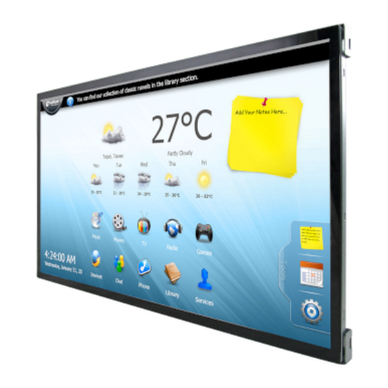
- Page 1 OFT-21W03 21.5" Open Frame Tablet Quick Reference Guide Ed – 07 February, 2022 Copyright Notice Copyright 2022 Avalue Technology Inc., ALL RIGHTS RESERVED. Part No. E2017T213A0R...
- Page 2 (2) Use only shielded cables to connect I/O devices to this equipment. (3) Changes or modifications not expressly approved by the party responsible for compliance could void the user’s authority to operate the equipment. 2 OFT-21W03 Quick Reference Guide...
- Page 3 RF exposure compliance, in order to comply with RF exposure limits established in the ANSI C95.1 standards, the distance between the antennas and the user should not be less than 20 cm. OFT-21W03 Quick Reference Guide...
- Page 4 “CAUTION - Use a power cord that matches the voltage of the power outlet, which has been approved and complies with the safety standard of your particular country.” “WARNING – To avoid risk of electric shock, this equipment must only be connected to a supply mains with protective earth.” 4 OFT-21W03 Quick Reference Guide...
-
Page 5: Table Of Contents
2.4.13 I2C Sensor (JSEN1) ........................46 2.4.14 Console Debug connector (JCOM1) ..................46 2.4.15 RS-232 connector (JCOM2) ...................... 47 2.4.16 RS-232 & RS-485 connector (JCOM3) ..................47 2.4.17 USB Camera & DMIC connector (JCAM1) ................48 OFT-21W03 Quick Reference Guide... - Page 6 OFT-21W03 2.4.18 RTD connector (JRTD1) ......................48 2.4.19 LVDS/eDP connector (JLCD1) ....................49 2.4.20 Backlight connector 1 (JBL1) ....................50 2.4.21 Backlight connector 2 (JBL2) ....................50 2.4.22 RTC battery connector (JBAT1) ....................51 6 OFT-21W03 Quick Reference Guide...
-
Page 7: Getting Started
1.2 Packing List 1 x OFT-21W03 1 x Screw M3-4mm / ziplock bag No.00 40x60mm x1pc 1 x power cord, AC/DC adapter 12V/5A 90 Screw Type (Option) OFT-21W03 Quick Reference Guide... -
Page 8: System Specifications
Touch Key Button Reset JPWR2: 2x2P_2mm_90D DC-IN(wafer) PWR-in 12V~24V JLCD1: 20x2P_1.25mm_180D LVDS / eDP Lvds dual 24bit, eDP, Hpd, Pwr-out(12v,5v,3.3v) (10.1” / 21.5”_LVDS, 15.6”_eDP) Analog MIC JAMIC1: 3P_2mm_90D 8 OFT-21W03 Quick Reference Guide... - Page 9 12V~24V wide voltage DC input Power Connector DC jack Type Dimension 501.88 x 296.2 x 44.1 mm Weight 3.4kg Color Metallic Fanless OS Support Win 10 / Ubuntu 19.04 OFT-21W03 Quick Reference Guide...
- Page 10 One corner, three edges, six faces Package Drop Test ISTA 2A, IEC-60068-2-32 Test: Ed Operating 0°C ~ 40°C Temperature Operating 40°C @ 95% Relative Humidity, Non-condensing Humidity Storage -20°C ~ 60°C Temperature 10 OFT-21W03 Quick Reference Guide...
- Page 11 Quick Reference Guide Note: Specifications are subject to change without notice. OFT-21W03 Quick Reference Guide 11...
-
Page 12: System Overview
Note Micro SD card slot Micro USB Micro USB connector Audio line-out connector HDMI HDMI connector 1 x USB 3.0 connector 1 x USB 2.0 connector RJ-45 Ethernet Reset button Reset DCIN DC power-in connector 12 OFT-21W03 Quick Reference Guide... -
Page 13: System Dimensions
Quick Reference Guide 1.5 System Dimensions 1.5.1 Front and Rear side (Unit: mm) OFT-21W03 Quick Reference Guide 13... -
Page 14: Installing Extend Brackets
Step1. Locate brackets on both sides, matching the holes on the monitor. Step2. Insert and fasten 14 screws on each side of the monitor to secure extending brackets. Step3. Fasten 4 screws to secure PCB & Shielding cover on the OFT-21W03 bracket. Note: Brackets sold separately. -
Page 15: Flush Mounting Concept
Quick Reference Guide 1.6 Flush Mounting Concept OFT-21W03 Quick Reference Guide 15... -
Page 16: Panel Mounting
OFT-21W03 1.7 Panel Mounting (Opening dimension) (Panel thickness) (Installation surface) (Unit: mm) 16 OFT-21W03 Quick Reference Guide... - Page 17 Quick Reference Guide Step1. Insert and fasten 4 screws to secure Bracket R/L. Screw Bracket-RL 21_ASSY Item Part Name Quantity OFT-21W03 Quick Reference Guide 17...
- Page 18 Step2-1. Locate brackets on both sides, matching the holes on the monitor. Step2-2. Insert and fasten 10 screws on each side of the monitor to secure Mounting brackets. Hexagon Stud 21_ASSY Item Part Name Quantity 18 OFT-21W03 Quick Reference Guide...
- Page 19 Quick Reference Guide Step3. Insert and fasten 10 screws on each side of the monitor to secure Front bracket. Front Bracket Screw Item Part Name Quantity OFT-21W03 Quick Reference Guide 19...
- Page 20 OFT-21W03 Step4. Insert and fasten 16 screws to secure Bracket. Screw Panel Mount Bracket Item Part Name Quantity 20 OFT-21W03 Quick Reference Guide...
- Page 21 Quick Reference Guide (Outside of the wall) Step5. Insert OFT-21W03 into the wall. Wall Item Part Name Quantity OFT-21W03 Quick Reference Guide 21...
- Page 22 OFT-21W03 (Inside of the wall) Step6. Fasten 12 screws to secure Panel mount brackets and insert it into Bracket. Panel mount Screw Panel Mount Kit Bracket Panel Mount Bracket Item Part Name Quantity 22 OFT-21W03 Quick Reference Guide...
- Page 23 Quick Reference Guide Step7. Insert and fasten 12 Panel mount screws to secure the module. Panel mount Screw Wall Item Part Name Quantity OFT-21W03 Quick Reference Guide 23...
- Page 24 OFT-21W03 Step8. Paste 2 U Plates on the Front bracket. U Plate Front Bracket Item Part Name Quantity 24 OFT-21W03 Quick Reference Guide...
- Page 25 Quick Reference Guide Step9. Paste the Decoration Plate on the U Plate to complete installation. Decoration Plate U Plate Item Part Name Quantity OFT-21W03 Quick Reference Guide 25...
-
Page 26: Wall Mounting Concept
OFT-21W03 1.8 Wall Mounting Concept 26 OFT-21W03 Quick Reference Guide... -
Page 27: Wall Mounting
Quick Reference Guide 1.9 Wall Mounting Size of the opening (Opening dimension) (Wall box installation dimension) (Installation surface) (Unit: mm) OFT-21W03 Quick Reference Guide 27... - Page 28 OFT-21W03 Screw hole location (Unit: mm) 28 OFT-21W03 Quick Reference Guide...
- Page 29 Quick Reference Guide Step1. Fasten the screw on the wall. Wall box Item Part Name Quantity OFT-21W03 Quick Reference Guide 29...
- Page 30 OFT-21W03 Step2. Insert and fasten 4 screws to secure Bracket R/L. Screw Bracket-RL 21_ASSY Item Part Name Quantity 30 OFT-21W03 Quick Reference Guide...
- Page 31 Quick Reference Guide Step3. Insert and fasten 10 screws on each side of the monitor to secure brackets. Hexagon Stud 21_ASSY Item Part Name Quantity OFT-21W03 Quick Reference Guide 31...
- Page 32 Step4-5. Insert the Support Bracket-H into the rectangular hole of the Wall mount kit and fasten 2 screws to secure Front bracket. This step is done 2 times in total) Support Bracket-V Support Bracket-H Wall mount kit Screw Front bracket Item Part Name Quantity 32 OFT-21W03 Quick Reference Guide...
- Page 33 Quick Reference Guide Step5. Insert and fasten 2 screws on Front bracket and Wall box of the monitor to secure Ground wire. Ground wire Screw Front bracket Wall box Item Part Name Quantity OFT-21W03 Quick Reference Guide 33...
- Page 34 OFT-21W03 Step6. Wrap the Kensington lock (option) around the hole in the front bracket and attach the lock to the keyhole in the Wall box. Kensington lock Front bracket Wall box Item Part Name Quantity 34 OFT-21W03 Quick Reference Guide...
- Page 35 Quick Reference Guide Step7-1. Insert the Ground wire and Kensington lock in the Wall box and Insert OFT-21W03 into the wall. Step7-2. Paste the U Bracket (2pcs) on the Front bracket. Step7-3. Paste the Decoration Plate on the U Bracket to complete installation.
-
Page 36: Hardware Configuration
OFT-21W03 2. Hardware Configuration For advanced information, please refer to: 1- Motherboard included in this manual. Note: If you need more information, please visit our website: http://www.avalue.com.tw 36 OFT-21W03 Quick Reference Guide... -
Page 37: Motherboard Overviews
Quick Reference Guide 2.2 Motherboard Overviews OFT-21W03 Quick Reference Guide 37... -
Page 38: Motherboard Connector List
5 x 1 wafer, pitch 2.00 mm JCOM3 RS-232 & RS-485 connector 5 x 2 wafer, pitch 2.00 mm JCAM1 USB Camera & DMIC connector 5 x 2 wafer, pitch 2.00 mm JSD1 Micro SD card slot 38 OFT-21W03 Quick Reference Guide... - Page 39 Warning: Risk of Explosion if Battery is replaced by an Incorrect Type. Dispose of Used Batteries According to the Instructions." Attention: Risque d'explosion si la batterie est remplacée par un type incorrect. Jetez les piles usagées selon les instructions. OFT-21W03 Quick Reference Guide 39...
-
Page 40: Motherboard Jumpers & Connectors Settings
OFT-21W03 2.4 Motherboard Jumpers & Connectors settings 2.4.1 Clear CMOS (JCMOS1) Protect* Clear CMOS Default 2.4.2 Backlight power select (JBLP1) 3.3V* * Default 40 OFT-21W03 Quick Reference Guide... -
Page 41: At/Atx Input Power Select (Jat1)
Quick Reference Guide 2.4.3 AT/ATX Input power select (JAT1) * Default 2.4.4 DC Power-in connector (JPWR2) Signal PIN PIN Signal DC-IN DC-IN OFT-21W03 Quick Reference Guide 41... -
Page 42: Touch Key Button (Jtk1)
OFT-21W03 2.4.5 Touch Key Button (JTK1) Signal PIN PIN Signal KEY_RST-BTN KEY_BU1 KEY_VOL-UP KEY_VOL-DN KEY_PWR-BTN KEY_BR-UP KEY_BR-DN KEY_BU7 LED_GRN LED_ORG 2.4.6 MCU connector (JMCU1) Signal PIC_MCLR PIC_ICSPCLK PIC_ICSPDAT 42 OFT-21W03 Quick Reference Guide... -
Page 43: Power Button (Jpb1)
Quick Reference Guide 2.4.7 Power button (JPB1) Signal KEY_PWR-BTN 2.4.8 Speaker interface (JSPK1) Signal SPK_L+ SPK_L- SPK_R+ SPK_R- OFT-21W03 Quick Reference Guide 43... -
Page 44: A-Mic Connector (Jamic1)
2.4.9 A-MIC connector (JAMIC1) Signal MIC_JD MIC_IN 2.4.10 General purpose I/O connector (JGPIO1) Signal PIN PIN Signal DIO_GP00 DIO_GP10 DIO_GP01 DIO_GP11 DIO_GP02 DIO_GP12 DIO_GP03 DIO_GP13 DIO_GP04 DIO_GP14 DIO_GP05 DIO_GP15 DIO_GP06 DIO_GP16 DIO_GP07 DIO_GP17 DIO_SDA_3.3 DIO_SCL_3.3 44 OFT-21W03 Quick Reference Guide... -
Page 45: I2C Touch Panel Connector (Jtp1)
Quick Reference Guide 2.4.11 I2C Touch Panel connector (JTP1) Signal +3.3V TP_INT# TP_SCL TP_SDA TP_RST# 2.4.12 USB Touch connector (JTP2) Signal USB_JTP2_N USB_JTP2_P OFT-21W03 Quick Reference Guide 45... -
Page 46: I2C Sensor (Jsen1)
OFT-21W03 2.4.13 I2C Sensor (JSEN1) Signal PIN PIN Signal +3.3V +3.3V SEN1_SCL SEN2_SCL SEN1_SDA SEN2_SDA SEN1_IRQP# SEN2_IRQP# 2.4.14 Console Debug connector (JCOM1) Signal COM1_TX_232 COM1_RX_232 COM1_AX7_P4_RX_232 COM1_AX7_P4_TX_232 46 OFT-21W03 Quick Reference Guide... -
Page 47: Rs-232 Connector (Jcom2)
Quick Reference Guide 2.4.15 RS-232 connector (JCOM2) Signal COM2_CTS_232 COM2_RTS_232 COM2_RX_232 COM2_TX_232 2.4.16 RS-232 & RS-485 connector (JCOM3) Signal PIN PIN Signal COM3_CTS_232 485+ COM3_RTS_232 485- COM3_RX_232 COM3_TX_232 OFT-21W03 Quick Reference Guide 47... -
Page 48: Usb Camera & Dmic Connector (Jcam1)
OFT-21W03 2.4.17 USB Camera & DMIC connector (JCAM1) Signal PIN PIN Signal DMIC_DATA USB_JCAM1_P DMIC_CLK USB_JCAM1_N +1.8V 2.4.18 RTD connector (JRTD1) Signal +3.3V RTD-EE_WP RTD-EE_SCL RTD-EE_SDA 48 OFT-21W03 Quick Reference Guide... -
Page 49: Lvds/Edp Connector (Jlcd1)
Quick Reference Guide 2.4.19 LVDS/eDP connector (JLCD1) Signal PIN PIN Signal +3.3V +3.3V EDP-HPD LVDS-TXO0+_EDP-TX0P LVDS-TXO1+_EDP-TX1P LVDS-TXO0-_EDP-TX0N LVDS-TXO1-_EDP-TX1N LVDS-TXO2+_EDP-AUXP 16 LVDS_TXO3+ LVDS-TXO2-_EDP-AUXN LVDS_TXO3- LVDS_TXE0+ LVDS_TXE1+ LVDS_TXE0- LVDS_TXE1- LVDS_TXE2+ LVDS_TXE3+ LVDS_TXE2- LVDS_TXE3- LVDS_TXOC+ LVDS_TXEC+ LVDS_TXOC- LVDS_TXEC- +12V +12V OFT-21W03 Quick Reference Guide 49... -
Page 50: Backlight Connector 1 (Jbl1)
OFT-21W03 2.4.20 Backlight connector 1 (JBL1) Signal +12V BL_EN BL_PWM 2.4.21 Backlight connector 2 (JBL2) Signal BKL_LED4 BKL_LED3 +38V +38V BKL_LED2 BKL_LED1 50 OFT-21W03 Quick Reference Guide... -
Page 51: Rtc Battery Connector (Jbat1)
Quick Reference Guide 2.4.22 RTC battery connector (JBAT1) Signal OFT-21W03 Quick Reference Guide 51...
Need help?
Do you have a question about the OFT-21W03 and is the answer not in the manual?
Questions and answers