
Related Manuals for Avalue Technology EPC-EHL-DIN


Summary of Contents for Avalue Technology EPC-EHL-DIN
- Page 1 EPC-EHL-B1 Intel® Elkhart Lake Fanless Compact System Quick Reference Guide Ed – 19 July 2023 Copyright Notice Copyright © 2023 Avalue Technology Inc., ALL RIGHTS RESERVED. Part No. E2017CAQ0A3R...
- Page 2 EPC-EHL-B1 FCC Statement THIS DEVICE COMPLIES WITH PART 15 FCC RULES. OPERATION IS SUBJECT TO THE FOLLOWING TWO CONDITIONS: (1) THIS DEVICE MAY NOT CAUSE HARMFUL INTERFERENCE. (2) THIS DEVICE MUST ACCEPT ANY INTERFERENCE RECEIVED INCLUDING INTERFERENCE THAT MAY CAUSE UNDESIRED OPERATION. THIS EQUIPMENT HAS BEEN TESTED AND FOUND TO COMPLY WITH THE LIMITS FOR A CLASS "A"...
-
Page 3: Table Of Contents
Rear View ..........................13 System Dimensions ..................... 18 1.5.1 EPC-EHL-B1 Front & Top View ..................... 18 1.5.2 EPC-EHL-DIN Front & Top View ................... 19 1.5.3 EPC-EHL-8USB Front & Top View ..................20 1.5.4 EPC-EHL-8COM Front & Top View ..................21 1.5.5... - Page 4 EPC-EHL-B1 2.4.17 Front Panel connector (JFP1) ....................36 2.4.18 PC Buzzer connector (JBZ1) ....................36 2.4.19 Cortex Debug + ETM connector (JPSE1) ................37 2.4.20 Port80 connector (JESPI1) ....................37 2.4.21 eDP connector (JEDP1) ......................38 2.4.22 Audio connector (JAUDIO1) ....................38 Signal Description –...
- Page 5 Quick Reference Guide 3.6.2.10 USB Configuration ......................60 3.6.2.11 Network Stack Configuration ..................... 61 3.6.2.12 NVMe Configuration ......................62 3.6.3 Chipset ..........................62 3.6.3.1 System Agent (SA) Configuration ..................63 3.6.3.1.1 Memory Configuration ....................... 63 3.6.3.1.2 Graphics Configuration...................... 64 3.6.3.2 PCH-IO Configuration .......................
-
Page 6: Getting Started
EPC-EHL-B1 1. Getting Started 1.1 Safety Precautions Warning! Always completely disconnect the power cord from your chassis whenever you work with the hardware. Do not make connections while the power is on. Sensitive electronic components can be damaged by sudden power surges. -
Page 7: System Specifications
Quick Reference Guide 1.3 System Specifications Component ECM-EHL-B1 ⚫ Intel Atom® x6413E Processor (1.5M Cache, up to 3.00 GHz) ⚫ One 260-pin SO-DIMM Socket, Supports Up to 32GB DDR4 3200MTs ⚫ Memory SDRAM BIOS AMI BIOS, 256Mbit SPI Flash ROM ⚫... - Page 8 EPC-EHL-B1 1 x Power on/off LED ⚫ LED Indicator 1 x Storage Access LED ⚫ DC Connector 1 x DC Jack ⚫ Audio Chipset Realtek ALC888S Audio Codec ⚫ Interface 1 x Mic-in, 1 x Line-out ⚫ Ethernet LAN Chipset Intel®...
- Page 9 Quick Reference Guide 6 System condition : Non-Operating mode ⚫ 7. Reference IEC 60068-2-6 Testing procedures ⚫ Package Vibration Test: ⚫ 1 Test PSD : 0.026G²/Hz , 2.16 Grms ⚫ 2 Test frequency : 5~500 Hz ⚫ 3 Test axis : X,Y and Z axis ⚫...
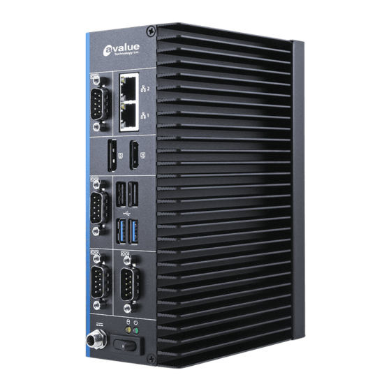
- Page 10 EPC-EHL-B1 ➢ Extended SKU Din Rail (EPC-EHL-DIN) Front I/O 2 x USB 3.1, 2 x USB2.0 4 x RS232 2 x RJ45 Antenna 2 x Antenna Mounting with Dust Protection Cover Power 1 x Power Switch LED Indicator 1 x Power on/off LED, 1 x Storage Access LED...
- Page 11 Quick Reference Guide Antenna 2 x Antenna Mounting with Dust Protection Cover Audio 1 x Mic-in, 1 x Line-out Display 1 x HDMI, 1 x DP LED Indicator 1 x Power on/off LED, 1 x Storage Access LED DC Connector 1 x DC Jack 4-LAN (EPC-EHL-4LAN) Front I/O...
-
Page 12: System Overview
EPC-EHL-B1 1.4 System Overview 1.4.1 Front View/Side View EPC-EHL-B1 EPC-EHL-8USB EPC-EHL-8COM 12 EPC-EHL-B1 Quick Reference Guide... -
Page 13: Rear View
Quick Reference Guide EPC-EHL-4LAN EPC-EHL-DIN 1.4.2 Rear View EPC-EHL-B1 EPC-EHL-B1 Quick Reference Guide 13... - Page 14 EPC-EHL-B1 EPC-EHL-DIN EPC-EHL-8USB EPC-EHL-8COM 14 EPC-EHL-B1 Quick Reference Guide...
- Page 15 USB 3.1 connector x 2 HDMI HDMI connector DP connector DC-IN DC Power-in connector LINE OUT Line-out audio jack MIC IN Mic-in audio jack EPC-EHL-DIN Connectors Label Function Note Power Power Switch HDD indicator System power indicator LAN1/2 RJ-45 Ethernet x 2...
- Page 16 EPC-EHL-B1 USB2.0 USB 2.0 connector x 2 USB3.1 USB 3.1 connector x 2 HDMI HDMI connector DP connector DC-IN DC Power-in connector LINE OUT Line-out audio jack MIC IN Mic-in audio jack EPC-EHL-8USB Connectors Label Function Note Power Power on button HDD indicator System power indicator LAN1/2...
- Page 17 Quick Reference Guide DC-IN DC Power-in connector LINE OUT Line-out audio jack MIC IN Mic-in audio jack EPC-EHL-4LAN Connectors Label Function Note Power Power on button HDD indicator System power indicator LAN1/2/3/4 RJ-45 Ethernet x 4 COM1/2 Serial port connector x 2 USB2.0 USB 2.0 connector x 2 USB3.1...
-
Page 18: System Dimensions
EPC-EHL-B1 1.5 System Dimensions 1.5.1 EPC-EHL-B1 Front & Top View (Unit: mm) 18 EPC-EHL-B1 Quick Reference Guide... -
Page 19: Epc-Ehl-Din Front & Top View
Quick Reference Guide 1.5.2 EPC-EHL-DIN Front & Top View (Unit: mm) EPC-EHL-B1 Quick Reference Guide 19... -
Page 20: Epc-Ehl-8Usb Front & Top View
EPC-EHL-B1 1.5.3 EPC-EHL-8USB Front & Top View (Unit: mm) 20 EPC-EHL-B1 Quick Reference Guide... -
Page 21: Epc-Ehl-8Com Front & Top View
Quick Reference Guide 1.5.4 EPC-EHL-8COM Front & Top View (Unit: mm) EPC-EHL-B1 Quick Reference Guide 21... -
Page 22: Epc-Ehl-4Lan Front & Top View
EPC-EHL-B1 1.5.5 EPC-EHL-4LAN Front & Top View (Unit: mm) 22 EPC-EHL-B1 Quick Reference Guide... -
Page 23: Hardware Configuration
Quick Reference Guide 2. Hardware Configuration For advanced information, please refer to: 1- ECM-EHL-B1 included in this manual Note: If you need more information, please visit our website: http://www.avalue.com.tw EPC-EHL-B1 Quick Reference Guide 23... -
Page 24: Epc-Ehl-B1 Connector Mapping
EPC-EHL-B1 2.1 EPC-EHL-B1 connector mapping 2.1.1 Serial Port connector (COM) Signal PIN PIN Signal DCD# DSR# RTS# CTS# DTR# 24 EPC-EHL-B1 Quick Reference Guide... -
Page 25: Ecm-Ehl-B1 Product Overview
Quick Reference Guide 2.2 ECM-EHL-B1 Product Overview EPC-EHL-B1 Quick Reference Guide 25... -
Page 26: Ecm-Ehl-B1 Jumper And Connector List
EPC-EHL-B1 2.3 ECM-EHL-B1 Jumper and Connector List You can configure your board to match the needs of your application by setting jumpers. A jumper is the simplest kind of electric switch. It consists of two metal pins and a small metal clip (often protected by a plastic cover) that slides over the pins to connect them. - Page 27 Quick Reference Guide JCOM2/3/4 Serial Port 2/3/4 connector 5 x 2 header, pitch 2.00mm JDIO1 General purpose I/O connector 6 x 2 wafer, pitch 2.00mm NGFF1 M.2 KEY-B 2242/3042 connector NGFF2 M.2 KEY-E 2230 connector LED1 HDD/Power LED indicator JFP1 Front Panel connector 5 x 2 header, pitch 2.00mm USB1...
-
Page 28: Ecm-Ehl-B1 Setting Jumpers & Connectors
EPC-EHL-B1 2.4 ECM-EHL-B1 Setting Jumpers & Connectors 2.4.1 Serial port 1 pin9 signal select (JRI1) Ring* +12V * Default 2.4.2 Clear CMOS (JBAT1) Normal* Clear CMOS * Default 28 EPC-EHL-B1 Quick Reference Guide... -
Page 29: At/Atx Input Power Select (Jat1)
Quick Reference Guide 2.4.3 AT/ATX Input power select (JAT1) * Default 2.4.4 LCD inverter connector (JBKL1) Signal +12V BKLEN VBRIGHT EPC-EHL-B1 Quick Reference Guide 29... -
Page 30: Cpu Fan Connector (Cpu_Fan1)
EPC-EHL-B1 2.4.5 CPU fan connector (CPU_FAN1) Signal CFAN_OUT_PWM CFAN_IN_TACH +12V 2.4.6 Serial port 1 in RS-422/485 mode (J422_485) Signal PIN PIN Signal 485TX2- 485TX2+ 485RX2+ 485RX2- 30 EPC-EHL-B1 Quick Reference Guide... -
Page 31: Serial Port 2 Connector (Jcom2)
Quick Reference Guide 2.4.7 Serial port 2 connector (JCOM2) Signal PIN PIN Signal COM_DCD#_2 COM_RXD_2 COM_TXD_2 COM_DTR#_2 COM_DSR#_2 COM_RTS#_2 COM_CTS#_2 COM_RI#_2 2.4.8 Serial port 3 connector (JCOM3) Signal PIN PIN Signal COM_DCD#_3 COM_RXD_3 COM_TXD_3 COM_DTR#_3 COM_DSR#_3 COM_RTS#_3 COM_CTS#_3 COM_RI#_3 EPC-EHL-B1 Quick Reference Guide 31... -
Page 32: Serial Port 4 Connector (Jcom4)
EPC-EHL-B1 2.4.9 Serial port 4 connector (JCOM4) Signal PIN PIN Signal COM_DCD#_4 COM_RXD_4 COM_TXD_4 COM_DTR#_4 COM_DSR#_4 COM_RTS#_4 COM_CTS#_4 COM_RI#_4 2.4.10 General purpose I/O connector (JDIO1) Signal PIN PIN Signal DIO_GP20_TGPI4 DIO_GP10_TGPI0 DIO_GP21_TGPI5 DIO_GP11_TGPI1 DIO_GP22_TGPI6 DIO_GP12_TGPI2 DIO_GP23_TGPI7 DIO_GP13_TGPI3 SMB_SCL_S0 SMB_SDA_S0 32 EPC-EHL-B1 Quick Reference Guide... -
Page 33: Sata Power Connector (Sata_Pwr1)
Quick Reference Guide 2.4.11 SATA Power connector (SATA_PWR1) Signal 2.4.12 Power connector (PWR1) Signal Signal +VIN_EXT +VIN_EXT EPC-EHL-B1 Quick Reference Guide 33... -
Page 34: Usb2.0 Connector (Jusb1)
EPC-EHL-B1 2.4.13 USB2.0 connector (JUSB1) Signal PIN PIN Signal +5VSB +5VSB USB_R_DN4 USB_R_DN5 USB_R_DP4 USB_R_DP5 2.4.14 BIOS SPI connector (BIOS_SPI1) Signal PIN PIN Signal +3.3VSB SPI_CS0# SPI_CLK SPI_MISO SPI_MOSI BIOS_HOLD# BIOS_WP# 34 EPC-EHL-B1 Quick Reference Guide... -
Page 35: Ec Debug Connector (Jec_Rom1)
Quick Reference Guide 2.4.15 EC Debug connector (JEC_ROM1) Signal EC_SMCLK_DBG EC_SMDAT_DBG 2.4.16 Battery connector (BT1) Signal +RTCBATT EPC-EHL-B1 Quick Reference Guide 35... -
Page 36: Front Panel Connector (Jfp1)
EPC-EHL-B1 2.4.17 Front Panel connector (JFP1) Signal PIN PIN Signal FP_HDD_LED+ FP_PWR_LED+ HDD_LED# PWR_LED# PMC_RSTBTN# PWR_BTN_IN_EC# 2.4.18 PC Buzzer connector (JBZ1) Signal SOC_SPKR_R 36 EPC-EHL-B1 Quick Reference Guide... -
Page 37: Cortex Debug + Etm Connector (Jpse1)
Quick Reference Guide 2.4.19 Cortex Debug + ETM connector (JPSE1) Signal PIN PIN Signal 19 PSE_TRACEDATA_3 17 PSE_TRACEDATA_2 15 PSE_TRACEDATA_1 TGTPWR_GND 13 PSE_TRACEDATA_0 TGTPWR_GND PSE_TRACECLK PSE_JTAG_GND_DET 10 PSE_JTAG_NRESET TP_TDI_PIN8 PSE_TRACESWO PSE_SWCLK +1.8VSB PSE_SWDIO 2.4.20 Port80 connector (JESPI1) Signal PIN PIN Signal ESPI_ALERT# ESPI_RST... -
Page 38: Edp Connector (Jedp1)
EPC-EHL-B1 2.4.21 eDP connector (JEDP1) Signal PIN PIN Signal EDP_Panel_TXN0 EDP_Panel_TXN3 EDP_Panel_TXP0 EDP_Panel_TXP3 EDP_Panel_TXN1 EDP_Panel_TXP1 11 12 EDP_Panel_AUXN 14 EDP_Panel_AUXP EDP_Panel_TXN2 15 EDP_Panel_TXP2 17 SOC_DDI0_HPD +VeDP +VeDP 2.4.22 Audio connector (JAUDIO1) Signal PIN PIN Signal FRONT-R-OUT FRONT-L-OUT HD_AGND HD_AGND LINE1-R-IN LINE1-L-IN MIC1-R-IN MIC1-L-IN... -
Page 39: Installing Hard Disk & Memory (Epc-Ehl-B1)
Quick Reference Guide 2.5 Installing Hard Disk & Memory (EPC-EHL-B1) Step1. Remove screws from the bottom of your system and take it off. Step2. Fix HDD using the 4 screws in the accessory kit. EPC-EHL-B1 Quick Reference Guide 39... - Page 40 EPC-EHL-B1 Step3. Properly install the memory modules and press until properly seated. 40 EPC-EHL-B1 Quick Reference Guide...
-
Page 41: Installing M.2 B-Key/M.2 E-Key Card (Epc-Ehl-B1)
Quick Reference Guide 2.6 Installing M.2 B-Key/M.2 E-Key card (EPC-EHL-B1) M.2 E-Key card M.2 B-Key card Step1. Insert M.2 B-Key/M.2 E-Key card into designated locations and fasten with the screws to complete installation. EPC-EHL-B1 Quick Reference Guide 41... -
Page 42: Installing Mounting Brackets (Epc-Ehl-B1)
EPC-EHL-B1 2.7 Installing Mounting Brackets (EPC-EHL-B1) Step1. Insert and fasten 4 screws on each side of the system to secure mounting brackets. 42 EPC-EHL-B1 Quick Reference Guide... -
Page 43: Bios Setup
Quick Reference Guide 3.BIOS Setup EPC-EHL-B1 Quick Reference Guide 43... -
Page 44: Introduction
EPC-EHL-B1 Introduction The BIOS setup program allows users to modify the basic system configuration. In this following chapter will describe how to access the BIOS setup program and the configuration options that may be changed. Starting Setup AMI BIOS™ is immediately activated when you first power on the computer. The BIOS reads the system information contained in the NVRAM and begins the process of checking out the system and configuring it. -
Page 45: Using Setup
Quick Reference Guide Using Setup In general, you use the arrow keys to highlight items, press <Enter> to select, use the PageUp and PageDown keys to change entries, press <F1> for help and press <Esc> to quit. The following table provides more detail about how to navigate in the Setup program using the keyboard. -
Page 46: Getting Help
EPC-EHL-B1 Getting Help Press F1 to pop up a small help window that describes the appropriate keys to use and the possible selections for the highlighted item. To exit the Help Window press <Esc> or the <Enter> key again. In Case of Problems If, after making and saving system changes with Setup, you discover that your computer no longer is able to boot, the AMI BIOS supports an override to the NVRAM settings which resets your system to its defaults. -
Page 47: Bios Setup
Quick Reference Guide BIOS setup Once you enter the Aptio Setup Utility, the Main Menu will appear on the screen. The Main Menu allows you to select from several setup functions and exit choices. Use the arrow keys to select among the items and press <Enter> to accept and enter the sub-menu. 3.6.1 Main Menu This section allows you to record some basic hardware configurations in your computer and... -
Page 48: System Language
EPC-EHL-B1 3.6.1.1 System Language This option allows choosing the system default language. 3.6.1.2 System Date Use the system date option to set the system date. Manually enter the day, month and year. 3.6.1.3 System Time Use the system time option to set the system time. Manually enter the hours, minutes and seconds. -
Page 49: Cpu Configuration
Quick Reference Guide 3.6.2.1 CPU Configuration Use the CPU configuration menu to view detailed CPU specification and configure the CPU. Item Options Description Disabled[Default] CPU Flex Ratio Override Enable/Disable CPU Flex Ratio Programming. Enabled When enabled, a VMM can utilize the additional Intel (VMX) Virtualization Disabled hardware capabilities provided by Vanderpool... -
Page 50: Power & Performance
EPC-EHL-B1 3.6.2.2 Power & Performance CPU – Power Management Control 3.6.2.2.1 Item Option Description Enabled[Default], Allows more than two frequency Intel® SpeedStep™ Disabled ranges to be supported. Eanble/Disable Intel® Speed Shift Intel® Speed Shift Enabled[Default], Technology support. Enabling will Technology Disabled expose the CPPC v2 interface to 50 EPC-EHL-B1 Quick Reference Guide... -
Page 51: View/Configure Turbo Options
Quick Reference Guide allow for hardware controlled P-states. Enable/Disable processor Turbo Enabled[Default], Mode (requires Intel Speed Step or Turbo Mode Disabled Intel Speed Shift to be available and enabled). Enable/Disable CPU Power Enabled[Default], Management. Allows CPU to go to C States C states when it’s not 100% Disabled utilized. -
Page 52: Gt - Power Management Control
EPC-EHL-B1 GT – Power Management Control 3.6.2.2.2 Item Option Description Enabled[Default], Check to enable render RC6(Render Standby) Disabled standby support. Default Max Frequency[Default] 100Mhz/150Mhz/200Mhz/250Mhz/300Mhz /350Mhz/400Mhz/450Mhz/500Mhz/550Mhz Maximum GT frequency Auto Updated. /600Mhz/650Mhz/700Mhz/750Mhz/800Mhz /850Mhz/900Mhz/950Mhz/1000Mhz/1050Mhz /1100Mhz/1150Mhz/1200Mhz Enabled: Disables Turbo GT Disable Turbo GT Enabled frequency. -
Page 53: Pch-Fw Configuration
Quick Reference Guide 3.6.2.3 PCH-FW Configuration Item Options Description Disabled, When Disabled ME will not be unconfigured on ME Unconfig on RTC Clear Enabled[Default] RTC Clear. 3.6.2.3.1 Firmware Update Configuration Item Option Description Disabled [Default], ME FW Image Re-Flash Enable/Disable Me FW Image Re-Flash function. Enabled EPC-EHL-B1 Quick Reference Guide 53... -
Page 54: Ptt Configuration
EPC-EHL-B1 3.6.2.3.2 PTT Configuration 3.6.2.4 Trusted Computing Item Options Description Enables or Disables BIOS support for security device. Disable, Security Device Support O.S. will not show Security Device. TCG EFI protocol Enable[Default] and INT1A interface will not be available. 54 EPC-EHL-B1 Quick Reference Guide... -
Page 55: Apci Settings
Quick Reference Guide 3.6.2.5 APCI Settings Item Options Description Enable ACPI Auto Disabled[Default], Enables or Disables BIOS ACPI Auto Configuration Enabled Configuration. Enables or Disables System ability to Disabled Hibernate (OS/S4 Sleep State). This Enable Hibernation Enabled[Default], option may not be effective with some Select the highest ACPI sleep state the Suspend Disabled, ACPI Sleep State... -
Page 56: Nct5124Dsec Super Io Configuration
EPC-EHL-B1 Item Options Description Enabled, Smart Fan Function Enables or Disables Smart Fan. Disabled[Default] 3.6.2.7 NCT5124DSEC Super IO Configuration You can use this item to set up or change the NCT5124DSEC Super IO configuration for serial ports. Please refer to 3.6.2.7.1 for more information. Item Description Serial Port 1 Configuration... -
Page 57: Serial Port 1 Configuration
Quick Reference Guide 3.6.2.7.1 Serial Port 1 Configuration Item Option Description Enabled[Default], Serial Port 1 Enable or Disable Serial Port (COM). Disabled UART 232[Default], Change the Serial Port as UART 232 422 485 UART 422 RS232/422/485. UART 485 3.6.2.7.2 Serial Port 2 Configuration EPC-EHL-B1 Quick Reference Guide 57... -
Page 58: Serial Port 3 Configuration
EPC-EHL-B1 Item Option Description Enabled[Default], Serial Port 2 Enable or Disable Serial Port (COM). Disabled 3.6.2.7.3 Serial Port 3 Configuration Item Option Description Enabled[Default], Serial Port 3 Enable or Disable Serial Port (COM). Disabled 3.6.2.7.4 Serial Port 4 Configuration Item Option Description Enabled[Default],... -
Page 59: S5 Rtc Wake Settings
Quick Reference Guide 3.6.2.8 S5 RTC Wake Settings Item Options Description Enable or disable System wake on alarm event. Select Disabled[Default], Fixed Time, system will wake on the hr::min::sec specified. Wake system from S5 Fixed Time Select Dynamic Time, System will wake on the current time Dynamic Time + Increase minute(s). -
Page 60: Usb Configuration
EPC-EHL-B1 Item Options Description Disabled[Default], Console Redirection Console Redirection Enable or Disable. Enabled Disabled[Default], Console Redirection EMS Console Redirection Enable or Disable. Enabled 3.6.2.10 USB Configuration The USB Configuration menu helps read USB information and configures USB settings. Item Options Description Enables Legacy USB support. -
Page 61: Network Stack Configuration
Quick Reference Guide Manual properly reports itself to the Host Controller. ‘Auto’ uses default value: for a Root port it is 100ms, for a Hub port the delay is taken form Hub descriptor. Mass storage device emulation type. ‘AUTO’ Auto[Default] Floppy enumerates devices according to their media Mass Storage Devices... -
Page 62: Nvme Configuration
EPC-EHL-B1 3.6.2.12 NVMe Configuration 3.6.3 Chipset 62 EPC-EHL-B1 Quick Reference Guide... -
Page 63: System Agent (Sa) Configuration
Quick Reference Guide 3.6.3.1 System Agent (SA) Configuration Item Option Description Enabled[Default] VT-d VT-d capability. Disabled Enable/Disable above 4GB Above 4GB MMIO BIOS Enabled MemoryMappedIO BIOS assignment. This assignment Disabled[Default] is enabled automatically when Aperture Size is set to 2048MB. 3.6.3.1.1 Memory Configuration EPC-EHL-B1 Quick Reference Guide 63... -
Page 64: Graphics Configuration
EPC-EHL-B1 3.6.3.1.2 Graphics Configuration Item Option Description Graphics turbo IMON current values supported Graphics Turbo IMON Current 14-31[Default] (14-31). Auto[Default] Select which of IGFX/PEG/PCI Graphics device IGFX Primary Display should be Primary Display Or select SG for Switchable Gfx. Auto[Default] Internal Graphics Disabled Keep IGFX enabled based on the setup options. -
Page 65: Pch-Io Configuration
Quick Reference Guide 3.6.3.2 PCH-IO Configuration 3.6.3.2.1 PCI Express Configuration EPC-EHL-B1 Quick Reference Guide 65... -
Page 66: Pci Express Root Port 1(M.2 Keyb)
EPC-EHL-B1 3.6.3.2.1.1 PCI Express Root Port 1(M.2 KeyB) Item Option Description PCI Express Root Port 1(M.2 Enabled[Default], Control the PCI Express Root Port. KeyB) Disabled Disabled[Default], Set the ASPM Level: Force L0s – Force all links to L0s State AUTO – BIOS auto ASPM configure DISABLE –... -
Page 67: Pci Express Root Port 3(M.2 Keye)
Quick Reference Guide 3.6.3.2.1.2 PCI Express Root Port 3(M.2 KeyE) Item Option Description PCI Express Root Port 3(M.2 Enabled[Default], Control the PCI Express Root Port. KeyE) Disabled Disabled[Default], Set the ASPM Level: Force L0s – Force all links to L0s State AUTO – BIOS auto ASPM configure DISABLE –... -
Page 68: Pci Express Root Port 4(I225/I226)
EPC-EHL-B1 3.6.3.2.1.3 PCI Express Root Port 4(i225/i226) Item Option Description PCI Express Root Port Enabled[Default], Control the PCI Express Root Port. 4(i225/i226) Disabled Disabled[Default], Set the ASPM Level: Force L0s – Force all links to L0s State AUTO – BIOS auto ASPM configure DISABLE –... -
Page 69: Pci Express Root Port 7(I225/I226)
Quick Reference Guide 3.6.3.2.1.4 PCI Express Root Port 7(i225/i226) Item Option Description PCI Express Root Port Enabled[Default], Control the PCI Express Root Port. 7(i225/i226) Disabled Disabled[Default], Set the ASPM Level: Force L0s – Force all links to L0s State AUTO – BIOS auto ASPM configure DISABLE –... -
Page 70: Pcie Clocks
EPC-EHL-B1 3.6.3.2.1.5 PCIE clocks Item Option Description Platform-POR= clock is assigned to PCIe Platform-POR[Default], port or LAN according to board layout. Clock0 assignment[Lan1] Enabled Enabled= keep clock enabledeven if unused. Disabled Disabled = Disable clock. Platform-POR= CLKREQ signal is assigned Platform-POR[Default], ClkReq for Clock0 to CLKSRC according to board layout. -
Page 71: Sata Configuration
Quick Reference Guide Platform-POR= CLKREQ signal is assigned Platform-POR[Default], ClkReq for Clock3 to CLKSRC according to board layout. Disabled Disabled = CLKREQ will not be used. 3.6.3.2.2 SATA Configuration Item Options Description Enabled[Default] SATA Controller(s) Enable/Disable SATA Device. Disabled, SATA Mode Selection AHCI[Default], Determines how SATA controller(s) operate. -
Page 72: Usb Configuration
EPC-EHL-B1 Enabled[Default] Port 1 Enable or Disable SATA Port. Disabled If enabled for any of ports Staggerred Spin Up Enabled will be performed and only the drives which Spin Up Device Disabled[Default] have this option enabled will spin up at boot. Otherwise all drives spin up at boot. -
Page 73: Hd Audio Configuration
Quick Reference Guide 3.6.3.2.4 HD Audio Configuration Item Option Description Control Detection of the HD-Audio device. Disable = HDA Disabled HD Audio will be unconditionally disabled Enabled = HDA will be Enabled[Default] unconditionally enabled. 3.6.3.3 Board & Panel Configuration EPC-EHL-B1 Quick Reference Guide 73... - Page 74 EPC-EHL-B1 Item Option Description BIOS[Default] eDP Brightness Control Method. 1.BIOS Brightness Control Method OS Driver 2.OS Driver. eDP Back Light PWM Select eDP back light PWM duty. 100%[Default] 200[Default] eDP Back Light PWM Select eDP back light PWM Frequency. Frequency Disabled[Default] ErP Function ErP Function (Deep S5).
-
Page 75: Security
Quick Reference Guide 3.6.4 Security ⚫ Administrator Password Set setup Administrator Password ⚫ User Password Set User Password 3.6.4.1 Secure Boot EPC-EHL-B1 Quick Reference Guide 75... -
Page 76: Key Management
EPC-EHL-B1 Item Option Description Secure Boot feature is Active if Secure Boot is Enable, Disabled[Default] Secure Boot Platform Key(PK) is enrolled and the System is in User Enabled mode. The mode change requires platform reset. Secure Boot mode selector: Standard/Custom. In Standard Secure Boot Mode Custom mode Secure Boot Variables can be configured... -
Page 77: Boot
Quick Reference Guide 3.6.5 Boot Item Option Description Number of seconds to wait for setup activation Setup Prompt Timeout 1~ 65535 key. 65535(0xFFFF) means indefinite waiting. On[Default] Bootup NumLock State Select the keyboard NumLock state Disabled[Default] Quiet Boot Enables or disables Quiet Boot option Enabled Enables or disables boot with initialization of a Disabled[Default]... -
Page 78: Save And Exit
EPC-EHL-B1 3.6.6 Save and exit 3.6.6.1 Save Changes and Reset Reset the system after saving the changes. 3.6.6.2 Discard Changes and Reset Any changes made to BIOS settings during this session of the BIOS setup program are discarded. The setup program then exits and reboots the controller. 3.6.6.3 Restore Defaults This option restores all BIOS settings to the factory default.
Need help?
Do you have a question about the EPC-EHL-DIN and is the answer not in the manual?
Questions and answers