
Related Manuals for Avalue Technology ECM-KA


Summary of Contents for Avalue Technology ECM-KA
- Page 1 ECM-KA AMD G-Series SoC Platform 3.5” Micro Module Quick Installation Guide Ed – 01 September 2013 Part No. E2017391601R http://www.Datasheet4U.com...
- Page 2 These answers are normally a lot more detailed than the ones we can give over the phone. So please consult the user’s manual first. To receive the latest version of the user’s manual; please visit our Web site at: http://www.avalue.com.tw/ 2 ECM-KA Quick Installation Guide...
- Page 3 Room 805, Building 9,No.99 Tianzhou Rd., 3F Ishiyama-Bldg, 1-6-1 Taito, Caohejing Development Area, Taito-ku, Tokyo 110-0016 Japan Tel : +81-3-5807-2321 Xuhui District, Shanghai Fax : +81-3-5807-2322 Tel: +86-21-5169-3609 Information : sales.japan@avalue.com.tw Fax:+86-21-5445-3266 Service : service@avalue.com.tw Information: sales.china@avalue.com.cn Service: service@avalue.com.tw ECM-KA Quick Installation Guide 3...
-
Page 4: Table Of Contents
On-board box header for USB2.0 (JUSB1) ........... 23 2.3.24 On-board box header for USB2.0 (JUSB2) ........... 23 2.3.25 On-board box header for USB2.0 (JUSB3) ........... 24 2.3.26 PS/2 keyboard & mouse connector (JKBMS) ........24 4 ECM-KA Quick Installation Guide... -
Page 5: Getting Started
Before you begin installing your single board, please make sure that the following materials have been shipped: 1 x 3.5” ECM-KA Micro Module 1 x Quick Installation Guide for ECM-KA 1 x AUX-032 daughter board W/Audio/4USB 1 x DVD-ROM contains the followings: ... -
Page 6: Hardware Configuration
ECM-KA Quick Installation Guide 2. Hardware Configuration 6 ECM-KA Quick Installation Guide... -
Page 7: Product Overview
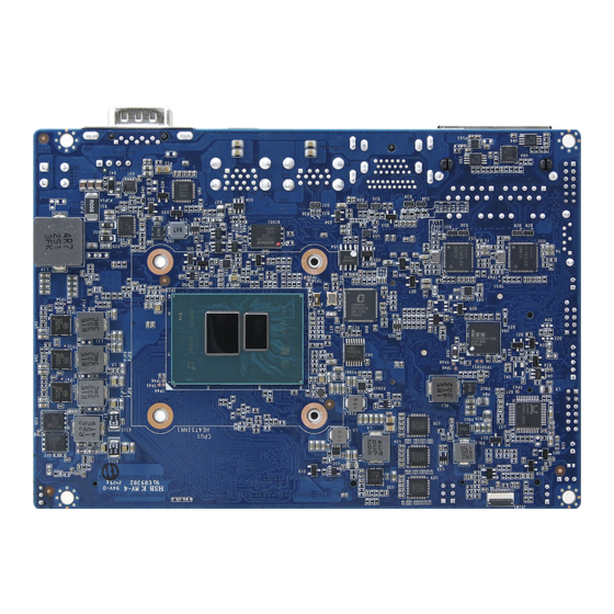
ECM-KA Quick Installation Guide 2.1 Product Overview ECM-KA Quick Installation Guide 7... - Page 8 ECM-KA Quick Installation Guide 8 ECM-KA Quick Installation Guide...
-
Page 9: Jumper And Connector List
Label Function Note JTOUCH1 Touch connector (option) 9 x 1 wafer, pitch 2.00 mm BAT1 Battery connector 2 x 1 wafer, pitch 1.25 mm CPU_FAN1 CPU fan connector 4 x 1 wafer, pitch 2.54 mm ECM-KA Quick Installation Guide 9... - Page 10 In order to facilitate USB 3.0 ports, no matter in a system or single board, please attach either PS2 keyboard/mouse or USB 2.0 keyboard/mouse to on-board USB 2.0 pin header in advance in order to install chip driver (USB 3.0 driver is included) in Windows. 10 ECM-KA Quick Installation Guide...
-
Page 11: Setting Jumpers & Connectors
ECM-KA Quick Installation Guide 2.3 Setting Jumpers & Connectors 2.3.1 Clear CMOS (JPCMOS1) Normal* CMOS Clear * Default 2.3.2 Touch connector select jumper (JTOUCH_SEL) (option) 4/8W * Default ECM-KA Quick Installation Guide 11... -
Page 12: Lcd Backlight Brightness Adjustment (Jvr1)
ECM-KA Quick Installation Guide 2.3.3 LCD backlight brightness adjustment (JVR1) PWM mode* DC mode * Default 2.3.4 AT/ ATX Input power select (JAT1) * Default 12 ECM-KA Quick Installation Guide... -
Page 13: Com 1 Pin 9 Signal Select (Jri1)
ECM-KA Quick Installation Guide 2.3.5 COM 1 pin 9 signal select (JRI1) Ring* +12V * Default 2.3.6 5VSB connector in ATX (PWR_SB1) Signal PS_ON# +V5A_ATX_SB ECM-KA Quick Installation Guide 13... -
Page 14: Battery Connector (Bat1)
ECM-KA Quick Installation Guide 2.3.7 Battery connector (BAT1) Signal +3.3V 2.3.8 CPU fan connector (CPU_FAN1) Signal +12V EC_TACH0 FAN_PWM0 14 ECM-KA Quick Installation Guide... -
Page 15: System Fan Connector (Sys_Fan1)
2.3.9 System fan connector (SYS_FAN1) Signal +12V EC_TACH1 FAN_PWM1 2.3.10 COM 1 RS-422-485 mode (J422/1) Signal PIN PIN Signal 485TX.RX-/422TX- 422RX+ 485TX.RX+/422TX+ 422RX- Note: J422/485 is available after modify the mode of COM1 in BIOS setting ECM-KA Quick Installation Guide 15... -
Page 16: Lcd Inverter Connector (Jbkl1)
ECM-KA Quick Installation Guide 2.3.11 LCD inverter connector (JBKL1) Signal +12V BKLEN BRIADJ 2.3.12 Low pin count connector (JLPC1) Signal PIN PIN Signal LPC_AD0 +3.3V LPC_AD1 LPC_RST# LPC_AD2 LPC_FRAME# LPC_AD3 LPC_CLK1 SERIRQ +V5S +V5A LDRQ0# 16 ECM-KA Quick Installation Guide... -
Page 17: Audio Connector (Jaudio1)
FRONT-L-OUT FRONT-R-OUT LINE1-L-IN LINE1-R-IN MIC1-L-IN MIC1-R-IN LINE1-JD FRONT-JD MIC1-JD 2.3.13.1 Signal Description – Audio connector (JAUDIO1) Signal Signal Description LINE1_JD AUDIO IN (LINE_RIN/LIN)sense pin FRONT_JD AUDIO Out(ROUT/LOUT) sense pin MIC1_JD MIC IN (MIC_RIN/LIN) sense pin ECM-KA Quick Installation Guide 17... -
Page 18: Serial Port 2 Connector (Jcom2)
ECM-KA Quick Installation Guide 2.3.14 Serial port 2 connector (JCOM2) Signal PIN PIN Signal RXDD2 DCD2 DTR2 TXDD2 DSR2 CTS2 RTS2 2.3.15 General purpose I/O connector (DIO1) Signal PIN PIN Signal SMB_CLK_9555 10 SMB_DATA_9555 +V5S_DIO 18 ECM-KA Quick Installation Guide... -
Page 19: Miscellaneous Setting Connector (Jfp1)
ECM-KA Quick Installation Guide 2.3.16 Miscellaneous setting connector (JFP1) Signal PWBT RST# PWR-LED- PWR-LED+ HDD-LED+ HDD-LED- COPEN# 2.3.17 SPI connector (JSPI1) Signal Signal +3.3V SPI_CS# SPI_CLK SPI_DI SPI_DO SPI_HOLD# ECM-KA Quick Installation Guide 19... -
Page 20: Ec_Program (Ec_Spi1)
ECM-KA Quick Installation Guide 2.3.18 EC_Program (EC_SPI1) Signal Signal +VSPI_EC EC_FSCE# EC_FSCK EC_FMISO EC_FMOSI EC_HOLD# 2.3.19 Power connector (PWR_IN1) Signal PIN PIN Signal +V_DCIN +V_DCIN 20 ECM-KA Quick Installation Guide... -
Page 21: Hdd Power Connector (Hd_Pwr1)
2.3.20 HDD power connector (HD_PWR1) Signal 2.3.21 Touch connector (JTOUCH1) (option) Signal 4-WIRE 5-WIRE 8-WIRE Right Sense Left Sense Bottom Sense SENSE Sense Top Sense Right Right Excite Left Left Excite Bottom Bottom Excite Top Excite ECM-KA Quick Installation Guide 21... -
Page 22: Lvds Connector (Jlvds1)
ECM-KA Quick Installation Guide 2.3.22 LVDS connector (JLVDS1) Signal PIN PIN Signal +12V +12V LVDS_CLK2_N LVDS_CLK1_N LVDS_CLK2_P LVDS_CLK1_P LVDS_DATA7_N LVDS_DATA6_N LVDS_DATA7_P LVDS_DATA6_P LVDS_DATA5_N LVDS_DATA4_N LVDS_DATA5_P LVDS_DATA4_P LVDS_DATA3_N LVDS_DATA2_N LVDS_DATA3_P LVDS_DATA2_P LVDS_DATA1_N LVDS_DATA0_N LVDS_DATA1_P LVDS_DATA0_P +3.3V +3.3V 22 ECM-KA Quick Installation Guide... -
Page 23: On-Board Box Header For Usb2.0 (Jusb1)
ECM-KA Quick Installation Guide 2.3.23 On-board box header for USB2.0 (JUSB1) Signal PIN PIN Signal USB_PN_Z_1 USB_PN_Z_0 USB_PP_Z_1 USB_PP_Z_0 2.3.24 On-board box header for USB2.0 (JUSB2) Signal PIN PIN Signal USB_PN_Z_2 USB_PN_Z_3 USB_PP_Z_2 USB_PP_Z_3 ECM-KA Quick Installation Guide 23... -
Page 24: On-Board Box Header For Usb2.0 (Jusb3)
ECM-KA Quick Installation Guide 2.3.25 On-board box header for USB2.0 (JUSB3) Signal PIN PIN Signal USB_PN_Z_4 USB_PN_Z_5 USB_PP_Z_4 USB_PP_Z_5 2.3.26 PS/2 keyboard & mouse connector (JKBMS) Signal PIN PIN Signal KBDT KBCK KBVCC MSDT MSCK 24 ECM-KA Quick Installation Guide...
Need help?
Do you have a question about the ECM-KA and is the answer not in the manual?
Questions and answers