
Related Manuals for Avalue Technology EPC-EHL


Summary of Contents for Avalue Technology EPC-EHL
- Page 1 EPC-EHL Intel® Elkhart Lake Fanless Compact System Quick Reference Guide Ed – 28 April 2022 Copyright Notice Copyright 2022 Avalue Technology Inc., ALL RIGHTS RESERVED. Part No. E2017CAQ0A0R...
- Page 2 These answers are normally a lot more detailed than the ones we can give over the phone. So please consult the user’s manual first. To receive the latest version of the user’s manual; please visit our Web site at: http://www.avalue.com.tw/ 2 EPC-EHL Quick Reference Guide...
-
Page 3: Table Of Contents
1.4.1 Front View/Side View ......................12 1.4.2 Rear View ..........................13 System Dimensions ..................... 18 1.5.1 EPC-EHL Front & Top View ....................18 1.5.2 EPC-EHL-DIN Front & Top View ................... 19 1.5.3 EPC-EHL-8USB Front & Top View ..................20 1.5.4 EPC-EHL-8COM Front &... - Page 4 Audio connector (JAUDIO1) ....................38 Signal Description – Audio connector (JAUDIO1) ............38 2.4.22.1 Installing Hard Disk & Memory (EPC-EHL) ............39 Installing M.2 B-Key/M.2 E-Key card (EPC-EHL) ..........41 Installing Mounting Brackets (EPC-EHL) ............. 42 3.BIOS Setup ........................43 Introduction ......................
- Page 5 Save Changes and Reset ....................79 3.6.6.4 Discard Changes and Reset ..................... 79 3.6.6.5 Save Changes ........................79 3.6.6.6 Discard Changes ....................... 79 3.6.6.7 Restore Defaults ........................ 79 3.6.6.8 Save as User Defaults....................... 79 3.6.6.9 Restore User Defaults ....................... 79 EPC-EHL Quick Reference Guide...
-
Page 6: Getting Started
Place all electronic components in a static-dissipative surface or static-shielded bag when they are not in the chassis. 1.2 Packing List 1 x EPC-EHL Intel® Elkhart Lake Fanless Compact System Other Major components Other major components include the ... -
Page 7: System Specifications
2 x RJ45 Antenna 4 x Antenna Mounting with Dust Protection Cover Audio 1 x Mic-in, 1 x Line-out 1 x HDMI, 1 x DP Display 1 x Power on/off LED LED Indicator EPC-EHL Quick Reference Guide... - Page 8 3 Sweep:1 Oct/ per one minute. (logarithmic) 4 Test Axis : X,Y and Z axis 5 Test time :30 min. each axis 6 System condition : Non-Operating mode 7. Reference IEC 60068-2-6 Testing procedures 8 EPC-EHL Quick Reference Guide...
- Page 9 4 Test drawing Software Support OS Information Win10 64 bit, Linux Certification Certification CE, FCC Class B Information Power Requirement Input: 100 ~ 240Vdc/ 50 ~ 60Hz Adapter Output: 12V/5A AC-DC 60W Adapter EPC-EHL Quick Reference Guide...
- Page 10 2 x USB 3.1, 2 x USB2.0 4 x RS232 2 x RJ45 2 x Antenna Mounting with Dust Protection Cover Antenna Audio 1 x Mic-in, 1 x Line-out Display 1 x HDMI, 1 x DP 10 EPC-EHL Quick Reference Guide...
- Page 11 2 x Antenna Mounting with Dust Protection Cover 1 x Mic-in, 1 x Line-out Audio 1 x HDMI, 1 x DP Display LED Indicator 1 x Power on/off LED, 1 x Storage Access LED Note: Specifications are subject to change without notice. EPC-EHL Quick Reference Guide 11...
-
Page 12: System Overview
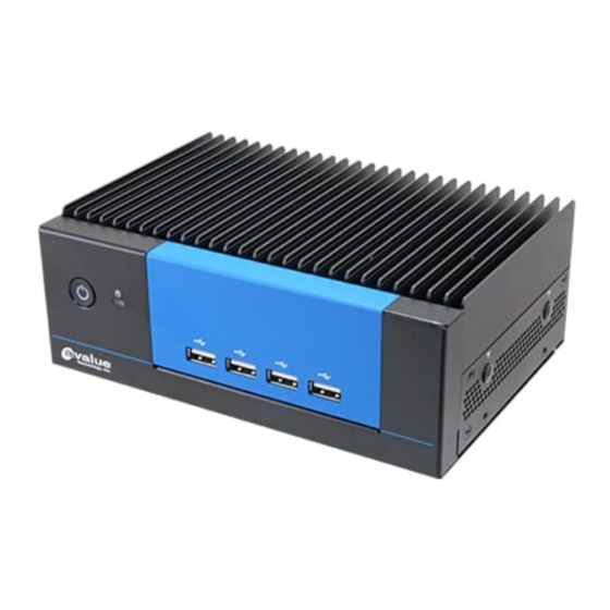
EPC-EHL 1.4 System Overview 1.4.1 Front View/Side View EPC-EHL EPC-EHL-8USB EPC-EHL-8COM 12 EPC-EHL Quick Reference Guide... -
Page 13: Rear View
Quick Reference Guide EPC-EHL-4LAN EPC-EHL-DIN 1.4.2 Rear View EPC-EHL EPC-EHL Quick Reference Guide 13... - Page 14 EPC-EHL EPC-EHL-DIN EPC-EHL-8USB EPC-EHL-8COM 14 EPC-EHL Quick Reference Guide...
- Page 15 HDMI connector DP connector DC-IN DC Power-in connector LINE OUT Line-out audio jack MIC IN Mic-in audio jack EPC-EHL-DIN Connectors Label Function Note Power Switch Power HDD indicator System power indicator LAN1/2 RJ-45 Ethernet x 2 EPC-EHL Quick Reference Guide 15...
- Page 16 Note Power on button Power HDD indicator System power indicator LAN1/2 RJ-45 Ethernet x 2 Serial port connector x 8 USB2.0 USB 2.0 connector x 2 USB3.1 USB 3.1 connector x 2 HDMI HDMI connector 16 EPC-EHL Quick Reference Guide...
- Page 17 Serial port connector x 2 USB2.0 USB 2.0 connector x 2 USB3.1 USB 3.1 connector x 2 HDMI HDMI connector DP connector DC-IN DC Power-in connector LINE OUT Line-out audio jack MIC IN Mic-in audio jack EPC-EHL Quick Reference Guide 17...
-
Page 18: System Dimensions
EPC-EHL 1.5 System Dimensions 1.5.1 EPC-EHL Front & Top View (Unit: mm) 18 EPC-EHL Quick Reference Guide... -
Page 19: Epc-Ehl-Din Front & Top View
Quick Reference Guide 1.5.2 EPC-EHL-DIN Front & Top View (Unit: mm) EPC-EHL Quick Reference Guide 19... -
Page 20: Epc-Ehl-8Usb Front & Top View
EPC-EHL 1.5.3 EPC-EHL-8USB Front & Top View (Unit: mm) 20 EPC-EHL Quick Reference Guide... -
Page 21: Epc-Ehl-8Com Front & Top View
Quick Reference Guide 1.5.4 EPC-EHL-8COM Front & Top View (Unit: mm) EPC-EHL Quick Reference Guide 21... -
Page 22: Epc-Ehl-4Lan Front & Top View
EPC-EHL 1.5.5 EPC-EHL-4LAN Front & Top View (Unit: mm) 22 EPC-EHL Quick Reference Guide... -
Page 23: Hardware Configuration
Quick Reference Guide 2. Hardware Configuration For advanced information, please refer to: 1- ECM-EHL included in this manual Note: If you need more information, please visit our website: http://www.avalue.com.tw EPC-EHL Quick Reference Guide 23... -
Page 24: Epc-Ehl Connector Mapping
EPC-EHL 2.1 EPC-EHL connector mapping 2.1.1 Serial Port connector (COM) Signal PIN PIN Signal DCD# DSR# RTS# CTS# DTR# 24 EPC-EHL Quick Reference Guide... -
Page 25: Ecm-Ehl Product Overview
Quick Reference Guide 2.2 ECM-EHL Product Overview EPC-EHL Quick Reference Guide 25... -
Page 26: Ecm-Ehl Jumper And Connector List
CPU fan connector 4 x 1 wafer, pitch 2.54mm D-sub 9-pin, male Note:COM1 support RS422/485 COM1 Serial Port 1 connector by BIOS setting Serial port 1 in RS-422/485 mode 3 x 2 header, pitch 2.00 mm J422_485 26 EPC-EHL Quick Reference Guide... - Page 27 SO_DIMM1 JPSE1 Cortex Debug + ETM connector 10 x 2 header, pitch 1.27mm JESPI1 Port80 connector 6 x 2 header, pitch 1.27mm JEDP1 eDP connector 10 x 2 wafer, pitch 1.25mm SIM card slot USIM1 EPC-EHL Quick Reference Guide 27...
-
Page 28: Ecm-Ehl Setting Jumpers & Connectors
EPC-EHL 2.4 ECM-EHL Setting Jumpers & Connectors 2.4.1 Serial port 1 pin9 signal select (JRI1) Ring* +12V * Default 2.4.2 Clear CMOS (JBAT1) Normal* Clear CMOS * Default 28 EPC-EHL Quick Reference Guide... -
Page 29: At/Atx Input Power Select (Jat1)
Quick Reference Guide 2.4.3 AT/ATX Input power select (JAT1) * Default 2.4.4 LCD inverter connector (JBKL1) Signal +12V BKLEN VBRIGHT EPC-EHL Quick Reference Guide 29... -
Page 30: Cpu Fan Connector (Cpu_Fan1)
EPC-EHL 2.4.5 CPU fan connector (CPU_FAN1) Signal CFAN_OUT_PWM CFAN_IN_TACH +12V 2.4.6 Serial port 1 in RS-422/485 mode (J422_485) Signal PIN PIN Signal 485TX2- 485TX2+ 485RX2+ 485RX2- 30 EPC-EHL Quick Reference Guide... -
Page 31: Serial Port 2 Connector (Jcom2)
Serial port 2 connector (JCOM2) Signal PIN PIN Signal COM_DCD#_2 COM_RXD_2 COM_TXD_2 COM_DTR#_2 COM_DSR#_2 COM_RTS#_2 COM_CTS#_2 COM_RI#_2 2.4.8 Serial port 3 connector (JCOM3) Signal PIN PIN Signal COM_DCD#_3 COM_RXD_3 COM_TXD_3 COM_DTR#_3 COM_DSR#_3 COM_RTS#_3 COM_CTS#_3 COM_RI#_3 EPC-EHL Quick Reference Guide 31... -
Page 32: Serial Port 4 Connector (Jcom4)
Serial port 4 connector (JCOM4) Signal PIN PIN Signal COM_DCD#_4 COM_RXD_4 COM_TXD_4 COM_DTR#_4 COM_DSR#_4 COM_RTS#_4 COM_CTS#_4 COM_RI#_4 2.4.10 General purpose I/O connector (JDIO1) Signal PIN PIN Signal DIO_GP20_TGPI4 DIO_GP10_TGPI0 DIO_GP21_TGPI5 DIO_GP11_TGPI1 DIO_GP22_TGPI6 DIO_GP12_TGPI2 DIO_GP23_TGPI7 DIO_GP13_TGPI3 SMB_SCL_S0 SMB_SDA_S0 32 EPC-EHL Quick Reference Guide... -
Page 33: Sata Power Connector (Sata_Pwr1)
Quick Reference Guide 2.4.11 SATA Power connector (SATA_PWR1) Signal 2.4.12 Power connector (PWR1) Signal Signal +VIN_EXT +VIN_EXT EPC-EHL Quick Reference Guide 33... -
Page 34: Usb2.0 Connector (Jusb1)
EPC-EHL 2.4.13 USB2.0 connector (JUSB1) Signal PIN PIN Signal +5VSB +5VSB USB_R_DN4 USB_R_DN5 USB_R_DP4 USB_R_DP5 2.4.14 BIOS SPI connector (BIOS_SPI1) Signal PIN PIN Signal +3.3VSB SPI_CS0# SPI_CLK SPI_MISO SPI_MOSI BIOS_HOLD# BIOS_WP# 34 EPC-EHL Quick Reference Guide... -
Page 35: Ec Debug Connector (Jec_Rom1)
Quick Reference Guide 2.4.15 EC Debug connector (JEC_ROM1) Signal EC_SMCLK_DBG EC_SMDAT_DBG 2.4.16 Battery connector (BT1) Signal +RTCBATT EPC-EHL Quick Reference Guide 35... -
Page 36: Front Panel Connector (Jfp1)
EPC-EHL 2.4.17 Front Panel connector (JFP1) Signal PIN PIN Signal FP_HDD_LED+ FP_PWR_LED+ HDD_LED# PWR_LED# PMC_RSTBTN# PWR_BTN_IN_EC# 2.4.18 PC Buzzer connector (JBZ1) Signal SOC_SPKR_R 36 EPC-EHL Quick Reference Guide... -
Page 37: Cortex Debug + Etm Connector (Jpse1)
17 PSE_TRACEDATA_2 15 PSE_TRACEDATA_1 TGTPWR_GND 13 PSE_TRACEDATA_0 TGTPWR_GND PSE_TRACECLK PSE_JTAG_GND_DET 10 PSE_JTAG_NRESET TP_TDI_PIN8 PSE_TRACESWO PSE_SWCLK +1.8VSB PSE_SWDIO 2.4.20 Port80 connector (JESPI1) Signal PIN PIN Signal ESPI_ALERT# ESPI_RST ESPI_CLK ESPI_IO3 ESPI_CS# ESPI_IO2 PLT_RST_BUF# ESPI_IO1 +3.3VSB ESPI_IO0 EPC-EHL Quick Reference Guide 37... -
Page 38: Edp Connector (Jedp1)
HD_AGND LINE1-R-IN LINE1-L-IN MIC1-R-IN MIC1-L-IN FRONT-JD LINE1-JD MIC1-JD HD_AGND 2.4.22.1 Signal Description – Audio connector (JAUDIO1) Signal Signal Description LINE1-JD AUDIO IN (LINE_RIN/LIN)sense pin FRONT-JD AUDIO Out(ROUT/LOUT) sense pin MIC1-JD MIC IN (MIC_RIN/LIN) sense pin 38 EPC-EHL Quick Reference Guide... -
Page 39: Installing Hard Disk & Memory (Epc-Ehl)
Quick Reference Guide 2.5 Installing Hard Disk & Memory (EPC-EHL) Step1. Remove screws from the bottom of your system and take it off. Step2. Fix HDD using the 4 screws in the Accessory Kit. EPC-EHL Quick Reference Guide 39... - Page 40 EPC-EHL Step3. Properly install the memory modules and press until properly seated. 40 EPC-EHL Quick Reference Guide...
-
Page 41: Installing M.2 B-Key/M.2 E-Key Card (Epc-Ehl)
Quick Reference Guide 2.6 Installing M.2 B-Key/M.2 E-Key card (EPC-EHL) M.2 E-Key card M.2 B-Key card Step1. Insert M.2 B-Key/M.2 E-Key card into designated locations and fasten with the screws to complete installation. EPC-EHL Quick Reference Guide 41... -
Page 42: Installing Mounting Brackets (Epc-Ehl)
EPC-EHL 2.7 Installing Mounting Brackets (EPC-EHL) Step1. Insert and fasten 4 screws on each side of the system to secure Mounting brackets. 42 EPC-EHL Quick Reference Guide... -
Page 43: Bios Setup
Quick Reference Guide 3.BIOS Setup EPC-EHL Quick Reference Guide 43... -
Page 44: Introduction
If the message disappears before you respond and you still wish to enter Setup, restart the system to try again by turning it OFF then ON or pressing the "RESET" button on the system case. You may also restart by simultaneously pressing <Ctrl>, <Alt>, and <Delete> keys. 44 EPC-EHL Quick Reference Guide... -
Page 45: Using Setup
Note: Some of the navigation keys differ from one screen to another. To Display a Sub Menu Use the arrow keys to move the cursor to the sub menu you want. Then press <Enter>. A “” pointer marks all sub menus. EPC-EHL Quick Reference Guide 45... -
Page 46: Getting Help
BIOS Vendor and your systems manufacturer to provide the absolute maximum performance and reliability. Even a seemingly small change to the chipset setup has the potential for causing you to use the override. 46 EPC-EHL Quick Reference Guide... -
Page 47: Bios Setup
<Enter> to accept and enter the sub-menu. 3.6.1 Main Menu This section allows you to record some basic hardware configurations in your computer and set the system clock. EPC-EHL Quick Reference Guide 47... -
Page 48: System Language
Visit the Avalue website (www.avalue.com.tw) to download the latest product and BIOS information. 3.6.2 Advanced Menu This section allows you to configure your CPU and other system devices for basic operation through the following sub-menus. 48 EPC-EHL Quick Reference Guide... -
Page 49: Cpu Configuration
Enable/Disable CPU Flex Ratio Programming. Enabled When enabled, a VMM can utilize the additional Intel (VMX) Virtualization Disabled hardware capabilities provided by Vanderpool Technology Enabled[Default] Technology. All[Default] Number of cores to enable in each processor Active Processor Cores package. EPC-EHL Quick Reference Guide 49... -
Page 50: Power & Performance
Max Battery Select the performance state that Boot performance mode Max Non-Turbo Performance[Default], the BIOS will set starting from reset Turbo Performance vector. Enabled[Default], Allows more than two frequency Intel® SpeedStep™ Disabled ranges to be supported. 50 EPC-EHL Quick Reference Guide... -
Page 51: View/Configure Turbo Options
Enable/Disable Energy Efficient Turbo Feature. This feature will opportunistically lower the turbo Disabled frequency to increase efficiency. Recommended Energy Efficient Turbo Enabled[Default] only to disable in overclocking situations where turbo frequency must remain constant. Otherwise, leave enabled. EPC-EHL Quick Reference Guide 51... -
Page 52: Gt - Power Management Control
RC6(Render Standby) Disabled standby support. Default Max Frequency[Default] 100Mhz/150Mhz/200Mhz/250Mhz/300Mhz /350Mhz/400Mhz/450Mhz/500Mhz/550Mhz Maximum GT frequency Auto Updated. /600Mhz/650Mhz/700Mhz/750Mhz/800Mhz /850Mhz/900Mhz/950Mhz/1000Mhz/1050Mhz /1100Mhz/1150Mhz/1200Mhz Enabled: Disables Turbo GT Disable Turbo GT Enabled frequency. Disabled: GT frequency Disabled[Default] frequency is not limited. 52 EPC-EHL Quick Reference Guide... -
Page 53: Pch-Fw Configuration
When Disabled ME will not be unconfigured on ME Unconfig on RTC Clear Enabled[Default] RTC Clear. 3.6.2.3.1 Firmware Update Configuration Item Option Description Disabled [Default], ME FW Image Re-Flash Enable/Disable Me FW Image Re-Flash function. Enabled EPC-EHL Quick Reference Guide 53... -
Page 54: Ptt Configuration
3.6.2.4 Trusted Computing Item Options Description Enables or Disables BIOS support for security device. Disable, Security Device Support O.S. will not show Security Device. TCG EFI protocol Enable[Default] and INT1A interface will not be available. 54 EPC-EHL Quick Reference Guide... -
Page 55: Apci Settings
Select the highest ACPI sleep state the Suspend Disabled, ACPI Sleep State system will enter when the SUSPEND S3 (Suspend to RAM)[Default] button is pressed. 3.6.2.6 HW Monitor EPC-EHL Quick Reference Guide 55... -
Page 56: Nct5124Dsec Super Io Configuration
Set Parameters of Serial Port 1 (COMA). Serial Port 2 Configuration Set Parameters of Serial Port 2 (COMB). Serial Port 3 Configuration Set Parameters of Serial Port 3 (COMC). Serial Port 4 Configuration Set Parameters of Serial Port 4 (COMD). 56 EPC-EHL Quick Reference Guide... -
Page 57: Serial Port 1 Configuration
Item Option Description Enabled[Default], Serial Port 1 Enable or Disable Serial Port (COM). Disabled UART 232[Default], Change the Serial Port as UART 232 422 485 UART 422 RS232/422/485. UART 485 3.6.2.7.2 Serial Port 2 Configuration EPC-EHL Quick Reference Guide 57... -
Page 58: Serial Port 3 Configuration
3.6.2.7.3 Serial Port 3 Configuration Item Option Description Enabled[Default], Serial Port 3 Enable or Disable Serial Port (COM). Disabled 3.6.2.7.4 Serial Port 4 Configuration Item Option Description Enabled[Default], Serial Port 4 Enable or Disable Serial Port (COM). Disabled 58 EPC-EHL Quick Reference Guide... -
Page 59: S5 Rtc Wake Settings
Fixed Time, system will wake on the hr::min::sec specified. Wake system from S5 Fixed Time Select Dynamic Time, System will wake on the current time Dynamic Time + Increase minute(s). 3.6.2.9 Serial Port Console Redirection EPC-EHL Quick Reference Guide 59... -
Page 60: Usb Configuration
Interrupt transfers. 20 sec[Default] 10 sec 20 sec[Default] USB mass storage device Start Unit command Device reset time-out 30 sec time-out. 40 sec Device power-up delay Auto[Default] Maximum time the device will take before it 60 EPC-EHL Quick Reference Guide... -
Page 61: Network Stack Configuration
Optical drives are emulated as ‘CDROM’, drives with no media will be Hard Disk CD-ROM emulated according to a drive type. 3.6.2.11 Network Stack Configuration Item Options Description Enabled Network Stack Enable/Disable UEFI Network Stack. Disabled[Default] EPC-EHL Quick Reference Guide 61... -
Page 62: Nvme Configuration
EPC-EHL 3.6.2.12 NVMe Configuration 3.6.3 Chipset 62 EPC-EHL Quick Reference Guide... -
Page 63: System Agent (Sa) Configuration
Item Option Description Enabled[Default] VT-d VT-d capability. Disabled Enable/Disable above 4GB Above 4GB MMIO BIOS Enabled MemoryMappedIO BIOS assignment. This assignment Disabled[Default] is enabled automatically when Aperture Size is set to 2048MB. 3.6.3.1.1 Memory Configuration EPC-EHL Quick Reference Guide 63... -
Page 64: Graphics Configuration
Select the GTT Size. 8MB[Default] 128MB Select the Aperture Size. Note: Above 4GB 256MB[Default] MMIO BIOS assignment is automatically enabled Aperture Size 512MB when selecting 2048MB aperture. To use this 1024MB feature, please disable CSM Support. 64 EPC-EHL Quick Reference Guide... -
Page 65: Pch-Io Configuration
Quick Reference Guide 3.6.3.2 PCH-IO Configuration 3.6.3.2.1 PCI Express Configuration EPC-EHL Quick Reference Guide 65... -
Page 66: Pci Express Root Port 1(M.2 Keyb)
L0s State AUTO – BIOS auto ASPM configure DISABLE – Disables ASPM. L0sL1 Auto Disabled[Default] L1 Substates L1.1 PCI Express L1 Substates settings. L1.1 & L1.2 Auto[Default] Gen1 PCIe Speed Configure PCIe Speed. Gen2 Gen3 66 EPC-EHL Quick Reference Guide... -
Page 67: Pci Express Root Port 3(M.2 Keye)
L0s State AUTO – BIOS auto ASPM configure DISABLE – Disables ASPM. L0sL1 Auto Disabled[Default] L1 Substates L1.1 PCI Express L1 Substates settings. L1.1 & L1.2 Auto[Default] Gen1 PCIe Speed Configure PCIe Speed. Gen2 Gen3 EPC-EHL Quick Reference Guide 67... -
Page 68: Pci Express Root Port 4(I225-Lm)
L0s State AUTO – BIOS auto ASPM configure DISABLE – Disables ASPM. L0sL1 Auto Disabled[Default], L1 Substates L1.1 PCI Express L1 Substates settings. L1.1 & L1.2 Auto[Default] Gen1 PCIe Speed Configure PCIe Speed. Gen2 Gen3 68 EPC-EHL Quick Reference Guide... -
Page 69: Pci Express Root Port 7(I210)
L0s State AUTO – BIOS auto ASPM configure DISABLE – Disables ASPM. L0sL1 Auto Disabled[Default], L1 Substates L1.1 PCI Express L1 Substates settings. L1.1 & L1.2 Auto[Default] Gen1 PCIe Speed Configure PCIe Speed. Gen2 Gen3 EPC-EHL Quick Reference Guide 69... -
Page 70: Pcie Clocks
Disabled = CLKREQ will not be used. Platform-POR= clock is assigned to PCIe Platform-POR[Default], port or LAN according to board layout. Clock3 assignment[M.2-M] Enabled Enabled= keep clock enabledeven if unused. Disabled Disabled = Disable clock. 70 EPC-EHL Quick Reference Guide... -
Page 71: Sata Configuration
Enable/Disable SATA Port 0 DevSlp. For DevSlp to work, both hard drive and SATA Disabled[Default] port need to support DevSlp function, SATA Port 0 DevSlp Enabled otherwise an unexpected behaviour might happen. Please check board design before enabling it. EPC-EHL Quick Reference Guide 71... -
Page 72: Usb Configuration
This option is to select USB3 Link Speed USB3 Link Speed Selection GEN2[Default], GEN1 or GEN2. Selectively Enable/Disable the corresponding Disabled[Default] USB Port Disable Override USB port from reporting a Device Connection Select-Per-Pin to the controller. 72 EPC-EHL Quick Reference Guide... -
Page 73: Hd Audio Configuration
3.6.3.2.4 HD Audio Configuration Item Option Description Control Detection of the HD-Audio device. Disable = HDA Disabled HD Audio will be unconditionally disabled Enabled = HDA will be Enabled[Default] unconditionally enabled. 3.6.3.3 Board & Panel Configuration EPC-EHL Quick Reference Guide 73... - Page 74 40 sec 50 sec Watch Dog Select WatchDog. 1 min 2 min 10 min 30 min Disabled Enable/Disabled USB Standby Power USB Standby Power Enabled[Default] during S3/S4/S5. Disabled[Default] SHOW DMI INFO SHOW DMI INFO. Enabled 74 EPC-EHL Quick Reference Guide...
-
Page 75: Security
Quick Reference Guide 3.6.4 Security Administrator Password Set setup Administrator Password User Password Set User Password 3.6.4.1 Secure Boot EPC-EHL Quick Reference Guide 75... -
Page 76: Key Management
Custom mode Secure Boot Variables can be configured Custom[Default] without authentication. 3.6.4.1.1 Key Management Item Option Description Install factory default Secure Boot keys after Disabled[Default] Factory Key Provision the platform reset and while the System is in Enabled Setup mode. 76 EPC-EHL Quick Reference Guide... -
Page 77: Boot
Enables or disables boot with initialization of a Disabled[Default] Fast Boot minimal set of devices required to launch active Enabled boot option. Has no effect for BBS boot options. Boot Option #1/#2 Set the system boot order. EPC-EHL Quick Reference Guide 77... -
Page 78: Save And Exit
Use the save changes and reset option to save the changes made to the BIOS options and to exit the BIOS configuration setup program. 3.6.6.2 Discard Changes and Exit Use the Discard changes and Exit option to exit the system without saving the changes made to the BIOS configuration setup program. 78 EPC-EHL Quick Reference Guide... -
Page 79: Save Changes And Reset
This option saves a copy of the current BIOS settings as the User Defaults. This option is useful for preserving custom BIOS setup configurations. 3.6.6.9 Restore User Defaults This option restores all BIOS settings to the user defaults. This option is useful for restoring previously preserved custom BIOS setup configurations. EPC-EHL Quick Reference Guide 79...
Need help?
Do you have a question about the EPC-EHL and is the answer not in the manual?
Questions and answers