Yeastar Technology S Series Installation Manual
Voip pbx
Hide thumbs
Also See for S Series:
- Administrator's manual (128 pages) ,
- Administrator's manual (123 pages) ,
- Getting started manual (21 pages)

Related Manuals for Yeastar Technology S Series


Summary of Contents for Yeastar Technology S Series
- Page 1 Installation Guide Installation_Guide Yeastar S-Series VoIP PBX December 4, 2019...
-
Page 2: Table Of Contents
Contents Installation Guide..............................3 Hardware Overview..............................3 S412 Overview..............................3 S20 Overview..............................5 S50 Overview..............................8 S100 Overview............................10 S300 Overview............................12 Expansion Board............................15 Install PBX................................16 Installation Warnings...........................16 Package Contents............................16 Install Yeastar S20............................17 Install Yeastar S50............................20 Install Yeastar S100............................24 Install Yeastar S300............................30 Install Yeastar S412............................36 Connect Your PBX............................. 38... -
Page 3: Installation Guide
Installation Guide Installation Guide for Yeastar S-Series VoIP PBX. About this guide This guide describes hardware ports and indicators on the Yeastar S-Series VoIP PBX, and give instructions on how to install the PBX and telephony modules. Hardware Overview S412 Overview Front Panel Table 1: Descriptions of S412 Front Panel Indication... - Page 4 Installation_Guide | 1 - Installation Guide | 4 Indication Status Description GSM/3G/4G Red: static The GSM/3G/4G Trunk is idle. (Line status) Red: blinking slowly No SIM card. Red: blinking rapidly The GSM/3G/4G trunk is in use. Orange: blinking The BRI line is disconnected. Orange: static The BRI line is connected or in use.
-
Page 5: S20 Overview
Installation_Guide | 1 - Installation Guide | 5 Table 2: Descriptions of S412 Rear Panel Port Description RJ11 • FXO port (red light): For the connection of PSTN lines or FXS ports of (Line port) traditional PBX. • BRI port (orange light): For the connection of ISDN BRI lines. Note: The sequence number of the ports corresponds to that of the Indicator lights in the front panel. - Page 6 Installation_Guide | 1 - Installation Guide | 6 Table 3: Descriptions of S20 Front Panel Indication Status Description POWER Power The power is switched on. status The power is switched off. SYSTEM System Blinking The system is running properly. status Static/Off The system goes wrong.
- Page 7 Installation_Guide | 1 - Installation Guide | 7 Indication Status Description Red: blinking rapidly The PSTN line is busy. Rear Panel Table 4: Descriptions of S20 Rear Panel Port Description RJ11 • FXO port (red light): For the connection of PSTN lines or FXS ports of traditional PBX.
-
Page 8: S50 Overview
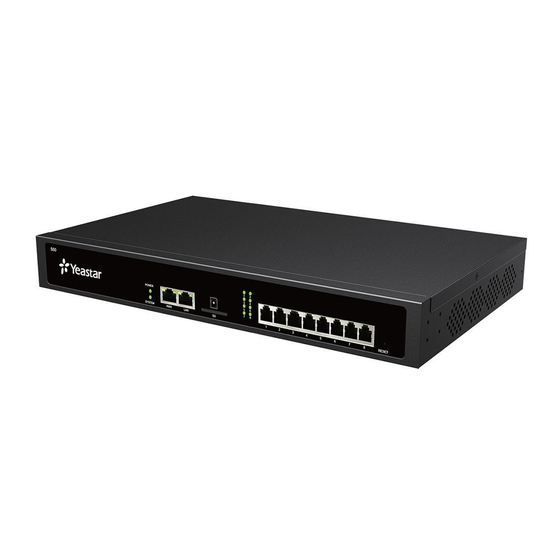
Installation_Guide | 1 - Installation Guide | 8 S50 Overview Front Panel Table 5: Descriptions of S50 Front Panel Indication Status Description POWER Power status The power is switched on. The power is switched off. SYSTEM System status Blinking The system is running properly. Static/Off The system goes wrong. - Page 9 Installation_Guide | 1 - Installation Guide | 9 Indication Status Description Red: blinking The PSTN line is busy. rapidly Port Description WAN/LAN Yeastar S50 provides two 10/100/1000Mbps adaptive RJ45 Ethernet ports, and supports 3 Ethernet modes. The default mode is “Single”. •...
-
Page 10: S100 Overview
Installation_Guide | 1 - Installation Guide | 10 Port Description Power Inlet Connect the supplied power supply to the port. Protective Connect to the ground to reduce the risk of electrocution to the user or protect the Earth PBX from the bad effects of external noise in the case of a lightning strike. S100 Overview Front Panel (1*EX30 + 1*EX08) Table 7: Descriptions of S100 Front Panel... - Page 11 Installation_Guide | 1 - Installation Guide | 11 Port Description Orange: blinking The BRI line is disconnected. Orange: static The BRI line is connected or in use. Red: static The PSTN line is idle. Red: blinking slowly No PSTN line is connected to the FXO port.
-
Page 12: S300 Overview
Installation_Guide | 1 - Installation Guide | 12 Indication Status Description Insert SD card to store auto recording files. Reset button Press and hold for 10 seconds to restore the factory defaults. Insert USB device to store auto recording files. Console Connect RS232 line to debug the system. - Page 13 Installation_Guide | 1 - Installation Guide | 13 Port Description 1-8 Port • FXO port (red light): For the connection of PSTN lines or FXS ports of traditional (RJ11 port) PBX. • FXS port (green light): For the connection of analog phones. •...
- Page 14 Installation_Guide | 1 - Installation Guide | 14 Rear Panel Table 10: Descriptions of S300 Rear Panel Indication Status Description POWER Power status The power is switched on. The power is switched off. SYSTEM System Blinking The system is running properly. status Static/Off The system goes wrong.
-
Page 15: Expansion Board
Installation_Guide | 1 - Installation Guide | 15 Indication Status Description Protective Connect to the ground to reduce the risk of electrocution to the user or protect the Earth PBX from the bad effects of external noise in the case of a lightning strike. Antenna Rotate the antenna into the Antenna Socket. -
Page 16: Install Pbx
Installation_Guide | 1 - Installation Guide | 16 D30 Module D30 is a DSP module, used to expand the capacity of PBX. With a D30 module added, the extensions increase 100 and concurrent calls increase 30 additionally. Install PBX Installation Warnings To avoid unexpected accident, personal injury or device damage, read the safety disclaimers and installation warnings. -
Page 17: Install Yeastar S20
Installation_Guide | 1 - Installation Guide | 17 Package Contents of S20 • 1* S20 PBX • 1* Power Adapter • 1* Ethernet Cable • 2* Telephony Line • 4* Rubber Feet • 1* Warranty Card • 1* Quick Installation Guide Package Contents of S50 •... - Page 18 Installation_Guide | 1 - Installation Guide | 18 • S2 Module • O2 Module • B2 Module • SO Module • GSM Module • 3G Module • 4G Module Note: Before installing the module, check if the module is clean and intact. 1.
- Page 19 Installation_Guide | 1 - Installation Guide | 19 4. Close the cover and fix the screws. 5. Rotate the antenna into the Antenna Socket. Skip this step if no GSM/3G/4G module installed.
-
Page 20: Install Yeastar S50
Installation_Guide | 1 - Installation Guide | 20 Desktop Installation Caution: • Set 5~10cm gaps around the device for air circulation. • Avoid any heavy thing placed on the device. 1. Place the PBX on a steady platform. 2. Remove the adhesive backing paper from the rubber feet. 3. - Page 21 Installation_Guide | 1 - Installation Guide | 21 1. Loosen the screws at the bottom of the device and remove the upper cover. 2. Insert the module to the Module Slot. 3. Follow the instructions to insert a SIM card on the GSM/3G/4G module. Note: Skip this step if no GSM/3G/4G module is installed.
- Page 22 Installation_Guide | 1 - Installation Guide | 22 4. Close the cover and fix the screws. 5. Rotate the antenna into the Antenna Socket. Skip this step if no GSM/3G/4G module installed. Desktop Installation Caution: • Set 5~10cm gaps around the device for air circulation. •...
- Page 23 Installation_Guide | 1 - Installation Guide | 23 Rack Installation Caution: • Be careful not to drop any components. Dropping components may damage them or cause an injury. • Only use the 19-inch rack mounting kits (attached bracket and fittings) included with the PBX. 1.
-
Page 24: Install Yeastar S100
Installation_Guide | 1 - Installation Guide | 24 Ground Connection Caution: • Proper grounding (connection to ground) is very important to reduce the risk of electrocution to the user or protect the PBX from the bad effects of external noise in the case of a lightning strike. •... - Page 25 Installation_Guide | 1 - Installation Guide | 25 2. Push out the empty board from the inside of the device. 3. Push in the Expansion Board (EX08 or EX30). 4. Lock the screws to fix the Expansion Board.
- Page 26 Installation_Guide | 1 - Installation Guide | 26 5. Insert the Telephony Modules on the EX08 Board. Note: Skip this step for EX30 Board. 6. Follow the instructions to insert a SIM card on the GSM/3G/4G module. Note: Skip this step if no GSM/3G/4G module is installed. 7.
- Page 27 Installation_Guide | 1 - Installation Guide | 27 8. Rotate the antenna into the Antenna Socket. Skip this step if no GSM/3G/4G module installed. Install DSP Module 1. Open the device upper cover and insert the DSP module (D30) into the D-Slot from a tilt angle and then press it down.
- Page 28 Installation_Guide | 1 - Installation Guide | 28 Desktop Installation Caution: • Set 5~10cm gaps around the device for air circulation. • Avoid any heavy thing placed on the device. 1. Place the PBX on a steady platform. 2. Remove the adhesive backing paper from the rubber feet. 3.
- Page 29 Installation_Guide | 1 - Installation Guide | 29 2. Place the PBX in the 19-inch rack and fix both brackets to the rack with the rack’s proprietary mounting equipment. Ground Connection Caution: • Proper grounding (connection to ground) is very important to reduce the risk of electrocution to the user or protect the PBX from the bad effects of external noise in the case of a lightning strike.
-
Page 30: Install Yeastar S300
Installation_Guide | 1 - Installation Guide | 30 Install Yeastar S300 Install Telephony Module Yeastar S300 supports: • Max. 3 EX08 Expansion Board • Max. 3 EX30 Expansion Board • Max. 12 Telephony Module • Max. 2 D30 Module The optional telephony modules are as below: •... - Page 31 Installation_Guide | 1 - Installation Guide | 31 3. Push in the Expansion Board (EX08 or EX30). 4. Lock the screws to fix the Expansion Board.
- Page 32 Installation_Guide | 1 - Installation Guide | 32 5. Insert the Telephony Modules on the EX08 Board. Note: Skip this step for EX30 Board. 6. Follow the instructions to insert a SIM card on the GSM/3G/4G module. Note: Skip this step if no GSM/3G/4G module is installed. 7.
- Page 33 Installation_Guide | 1 - Installation Guide | 33 8. Rotate the antenna into the Antenna Socket. Note: Skip this step if no GSM/3G/4G module installed. Install DSP Module 1. Open the device upper cover and insert the DSP module (D30) into the D-Slot from a tilt angle and then press it down.
- Page 34 Installation_Guide | 1 - Installation Guide | 34 Desktop Installation Caution: • Set 5~10cm gaps around the device for air circulation. • Avoid any heavy thing placed on the device. 1. Place the PBX on a steady platform. 2. Remove the adhesive backing paper from the rubber feet. 3.
- Page 35 Installation_Guide | 1 - Installation Guide | 35 2. Place the PBX in the 19-inch rack and fix both brackets to the rack with the rack’s proprietary mounting equipment. Ground Connection Caution: • Proper grounding (connection to ground) is very important to reduce the risk of electrocution to the user or protect the PBX from the bad effects of external noise in the case of a lightning strike.
-
Page 36: Install Yeastar S412
Installation_Guide | 1 - Installation Guide | 36 Install Yeastar S412 Install Telephony Module Yeastar S412 is designed with 8 fixed on-board FXS ports and 4 reserved slots. You can insert different modules into the 4 reserved slots according to your needs. Yeastar S412 supports installing up to 4 modules. The optional modules are as below: •... - Page 37 Installation_Guide | 1 - Installation Guide | 37 3. Follow the instructions to insert a SIM card on the GSM/3G/4G module. Note: Skip this step if no GSM/3G/4G module is installed. 4. Close the cover and fix the screws. 5. Rotate the antenna into the Antenna Socket. Note: Skip this step if no GSM/3G/4G module installed.
-
Page 38: Connect Your Pbx
Installation_Guide | 1 - Installation Guide | 38 Desktop Installation Caution: • Set 5~10cm gaps around the device for air circulation. • Avoid any heavy thing placed on the device. 1. Place the PBX on a steady platform. 2. Remove the adhesive backing paper from the rubber feet. 3. - Page 39 Installation_Guide | 1 - Installation Guide | 39 1. Connect your PBX to the network. Connect one end of an Ethernet cable to the LAN port of your PBX, and the other end to any port of your company’s LAN switch/router. 2.
Need help?
Do you have a question about the S Series and is the answer not in the manual?
Questions and answers