
Related Manuals for EDAN SD5


Summary of Contents for EDAN SD5
- Page 2 This manual will help you understand the operation and maintenance of the product better. It is reminded that the product shall be used strictly complying with this manual. User’s operation failing to comply with this manual may result in malfunction or accident for which EDAN INSTRUMENTS, INC. (hereinafter called EDAN) can not be held liable.
- Page 3 CAUTION A CAUTION label advises against actions or situations that could damage equipment, produce inaccurate data, or invalidate a procedure. NOTE A NOTE provides useful information regarding a function or a procedure.
-
Page 4: Table Of Contents
Table of Contents Chapter 1 Safety Guide .........................1 1.1 Safety Precautions.......................1 1.2 Symbols..........................2 Chapter 2 Introduction........................4 2.1 Intended Use........................4 2.2 Major Parts ..........................4 2.2.1 Main Unit ........................4 2.2.2 Probes........................6 2.2.3 Control Keys ......................7 2.2.4 Indicators........................8 2.2.5 LCD...........................8 Chapter 3 Basic Operation......................10 3.1 Opening Package and Checking..................10 3.2 Using Batteries ........................10 3.2.1 Fitting Main Unit Battery..................10... - Page 5 EQUIPMENT or SYSTEM- For EQUIPMENT or SYSTEM that are not LIFE-SUPPORTING ......................36 Appendix 3 Overall Sensitivity ....................37 A3.1 Overall Sensitivity of SD5 (2MHz Wired Probe) ............37 A3.2 Overall Sensitivity of SD5 (3MHz Wired Probe) ............38 A3.3 Overall Sensitivity of SD6 (2MHz Wireless Probe) ............39...
-
Page 6: Chapter 1 Safety Guide
(i.e. not drip or splash-proof). Keep the device clean. Avoid vibration. Apply the SD5/SD6 in an environment with a temperature between +5 ºC (+41 ºF) and +40 ºC (+104 ºF). Electromagnetic Interference - Ensure that the environment in which the device is operated is not subject to any source of strong electromagnetic interference, such as radio transmitters, mobile telephones, etc.. -
Page 7: Symbols
SD5/SD6 Ultrasonic TableTop Doppler User Manual Safety Guide CAUTION Check that the equipment does not have visible evidence of damage that may affect personnel’s safety or examining capability before use. If damage is detected, replacement is recommended. The device and accessories are to be disposed of according to local regulations after their useful lives. - Page 8 SD5/SD6 Ultrasonic TableTop Doppler User Manual Safety Guide Caution. Refer to accompanying documents. Consult Instructions for Use Type B applied part. This symbol indicates the unit is internally powered equipment, and the degree of protection against electrical shock is type B.
-
Page 9: Chapter 2 Introduction
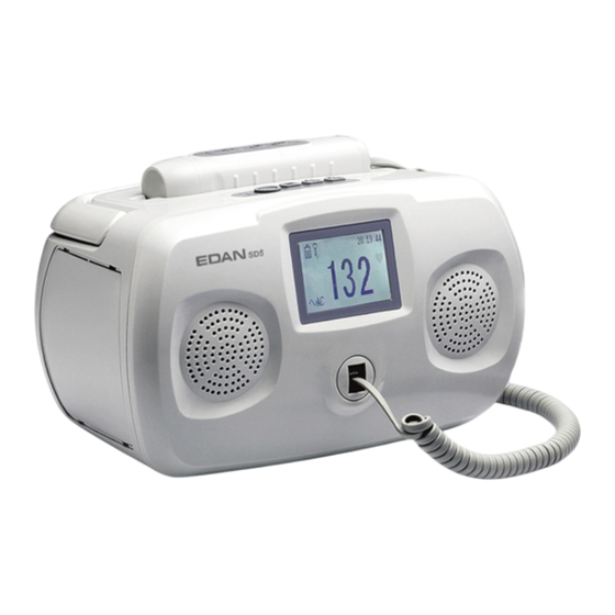
Chapter 2 Introduction 2.1 Intended Use The SD5 Ultrasonic TableTop Doppler (hereinafter called “SD5”) and SD6 Ultrasonic TableTop Doppler (hereinafter called “SD6”) are intended to be used by health care professionals including registered nurses, practical nurses, midwives, ultrasound technicians, and physician assistants, by prescription from licensed physicians in hospitals, clinics and private offices. - Page 10 SD5/SD6 Ultrasonic TableTop Doppler User Manual Introduction 8 Probe Holder 9 Handle 10 Probe Sensor Socket 11 Main Unit Control Keys Figure 2-2 Top View of the Main Unit 12 Main Unit Indicator 13 On/OFF Key 14 Setup Key / Confirm Key...
-
Page 11: Probes
SD5/SD6 Ultrasonic TableTop Doppler User Manual Introduction NOTE: The main unit is not waterproof. Do not immerse it in any type of liquid. 2.2.2 Probes Wireless Probe: 1 Acoustic Face 2 Probe Control Keys 3 Infrared Sender 4 Probe Socket... -
Page 12: Control Keys
The Doppler supports 2MHz, 3MHz, 4MHz, 5MHz and 8MHz probes supplied by the manufacturer. The probe nominal frequency is disclosed on the probe type label. Probes of SD5 are wired, while probes of SD6 are wireless. WARNING Do not touch the charge sockets of the Wireless Doppler probe and the patient at the same time. -
Page 13: Indicators
SD5/SD6 Ultrasonic TableTop Doppler User Manual Introduction 2.2.4 Indicators (1) Main unit indicator The indicator of the main unit indicates the connection status of the main unit and AC power: The indicator lights up in green – the AC power is connected. - Page 14 SD5/SD6 Ultrasonic TableTop Doppler User Manual Introduction Infrared Indicator Infrared signal is received. (Only available with SD6) Infrared signal is not received, indicating that poor quality signal is received. Probe Indicator The probe is well connected. (Only available with SD5) The probe is not connected.
-
Page 15: Chapter 3 Basic Operation
SD5/SD6 Ultrasonic TableTop Doppler User Manual Basic Operation Chapter 3 Basic Operation 3.1 Opening Package and Checking Open the package; take out the Doppler and accessories carefully. Place them on a flat, clean surface. Keep the package for possible future transportation or storage. Check the components according to the packing list. - Page 16 SD5/SD6 Ultrasonic TableTop Doppler User Manual Basic Operation Metal Insert Battery Connecting Cable & Connector 2 Tilt the battery sideways and put its bottom left corner into the battery compartment from the left end of the compartment to the right. Make sure connector ① stays out of the compartment.
-
Page 17: Fitting Wireless Probe Battery
SD5/SD6 Ultrasonic TableTop Doppler User Manual Basic Operation 4 Connect the two connectors (①&②) and then put them into the compartment. 5 Close the battery compartment cover. 3.2.2 Fitting Wireless Probe Battery The wireless probe is powered by a lithium battery. -
Page 18: Charging Main Unit Battery
SD5/SD6 Ultrasonic TableTop Doppler User Manual Basic Operation 2 Fit the battery. Make sure the polarities correspond with the battery compartment diagram. 3 Close the battery compartment cover and fix it with the screw. 3.2.3 Charging Main Unit Battery Observe the battery indicator on the LCD, the panes in it indicate the main unit battery electric energy. -
Page 19: Care Of Batteries
If the protective grounding (protective earth) system is doubtful, the power of the Doppler must be supplied only by inner power. 3.4 Using Wired Probe 3.4.1 Probe Socket SD5 adopts wired probes. The probe cable is a telephone cable with a standard RJ11 plug on each terminal. - 14 -... -
Page 20: Connecting And Disconnecting A Wired Probe
SD5/SD6 Ultrasonic TableTop Doppler User Manual Basic Operation RJ11 Interface: Power VCC +5V Signal Wire Signal Wire 3.4.2 Connecting and Disconnecting a Wired Probe To connect the wired probe to the main unit, 1 Take out the probe cable from package. Insert one modular plug of the cable into the probe socket of the main unit. -
Page 21: Switching Off
SD5/SD6 Ultrasonic TableTop Doppler User Manual Basic Operation CAUTION To avoid unwanted noise, do not take out or place the probe when the main unit is on. Remember to take out the probe before switching on the main unit, and place the probe after switching off the main unit. -
Page 22: Using Earphone
SD5/SD6 Ultrasonic TableTop Doppler User Manual Basic Operation 3.7 Using Earphone In a noisy environment, the earphone is recommended to hear ideal fetal heart sound. Insert the earphone plug into earphone socket on the back of the main unit (figure 2-4). The speakers will be muted when the earphone is connected. - Page 23 SD5/SD6 Ultrasonic TableTop Doppler User Manual Basic Operation 3 The lock is securely attached to the main unit. Hitch the device to a stationary object. To unlock the main unit, Insert the key into the lock slot. Apply a certain amount of pressure to the key and then rotate it clockwise.
-
Page 24: Changing Doppler Settings
SD5/SD6 Ultrasonic TableTop Doppler User Manual Basic Operation 3.9 Changing Doppler Settings 3.9.1 Switching Backlight On and Off 1 Press the Setup key to open setup menu. 2 Press the Setup key when the cursor stays at Backlight. 3 Press the Up/Down key to toggle between ON and OFF. -
Page 25: Setting Date Format
SD5/SD6 Ultrasonic TableTop Doppler User Manual Basic Operation 3.9.6 Setting Date Format You can choose to switch the date on or off. When it is on, the date format has three options: DD/MM/YYYY, MM/DD/YYYY and YYYY/MM/DD. To switch the date on and off or change date format, 1 Press the Setup key to open setup menu. -
Page 26: Chapter 4 Examining
SD5/SD6 Ultrasonic TableTop Doppler User Manual Examining Chapter 4 Examining WARNING Always check if the main unit and the probe are in good condition prior to use. CAUTION Handle the probe with care. Do not drop it on hard surfaces. -
Page 27: Vascular Examining
SD5/SD6 Ultrasonic TableTop Doppler User Manual Examining Special notes for using SD6: 1 To ensure good communication, make sure there is no barrier between the infrared sender on the probe and the infrared receivers on the main unit. Aiming the infrared sender of the probe to the main unit allows the best communication result. - Page 28 SD5/SD6 Ultrasonic TableTop Doppler User Manual Examining Vertebral Artery (5MHz) Carotid Artery (5/8MHz) Carotid Artery (5/8MHz) Jugular Vein (5MHz) Subclavian Artery (5MHz) Subclavian Vein (5MHz) Brachial Artery (8MHz) Ulner Artery (8MHz) Radial Artery (8MHz) Femoral Artery (5MHz) Femoral Vein (5MHz)
-
Page 29: Chapter 5 Recording And Playing
SD5/SD6 Ultrasonic TableTop Doppler User Manual Recording and Playing Chapter 5 Recording and Playing The built-in recorder of the Doppler provides recording and playing fetal heart sound of 240 seconds (at most). To record fetal heart sound, Press and hold the Record/Play control key for two seconds. -
Page 30: Chapter 6 Maintenance And Cleaning
SD5/SD6 Ultrasonic TableTop Doppler User Manual Maintenance and Cleaning Chapter 6 Maintenance and Cleaning 6.1 Inspection (1) Visual Inspection Prior to using the device every time, do the following inspections: Check the device and accessories to see if there is any visible evidence of damage that may affect patient safety. -
Page 31: Cleaning
SD5/SD6 Ultrasonic TableTop Doppler User Manual Maintenance and Cleaning Handle the probe with care to avoid damaging the cover, piezoelectric crystals and mechanical movement. Do not contact the probe with hard or sharp objects. Do not excessively flex the probe cable. -
Page 32: Chapter 7 Warranty And Service
EDAN will, at its discretion, repair or replace the defective part(s) free of charge. EDAN will not provide a substitute product for use when the defective product is being repaired. -
Page 33: Chapter 8 Product Specifications
SD5/SD6 Ultrasonic TableTop Doppler User Manual Product Specifications Chapter 8 Product Specifications 8.1 Environmental Specifications Temperature: +5 ºC ~+ 40 ºC ( +41 ºF ~ +104 ºF) Working Relative Humidity: 25% ~ 80% (non-condensing) Atmospheric Pressure: 860hPa ~ 1060hPa Temperature: -20 ºC ~ +55 ºC (-4ºF ~ +131 ºF) -
Page 34: Performance Specifications
SD5/SD6 Ultrasonic TableTop Doppler User Manual Product Specifications Main Unit: Not-protected Degree Protection against Harmful Ingress of Water Probe: IPX4 Degree of Safety in Presence of Equipment not suitable for use in presence of Flammable Gases flammable gases Disinfection/Sterilizing Method... -
Page 35: Battery Specifications
SD5/SD6 Ultrasonic TableTop Doppler User Manual Product Specifications Ultrasound: 2MHz Wired /Wireless Probes: 2MHz 3MHz Wired /Wireless Probes: 3MHz Nominal Frequency: 4MHz Wired /Wireless Probes: 4MHz 5MHz Wired /Wireless Probes: 5MHz 8MHz Wired /Wireless Probes: 8MHz 2MHz Wired /Wireless Probes: (2.0 ± 10%)MHz 3MHz Wired /Wireless Probes: (3.0 ±... -
Page 36: Low Output Summary Table
SD5/SD6 Ultrasonic TableTop Doppler User Manual Product Specifications Nominal Capacity: 2000mAh 700mAh Nominal Voltage: 7.2V 3.7V Charge Current (Standard): 757mA 500mA Charge Voltage (Standard): 4.2V Necessary Charge Time Approx. 3h 4h ~ 5h Expected Battery Life: Approx. 10h Approx. 3h... -
Page 37: Appendix 1 Ordering Information
SD5/SD6 Ultrasonic TableTop Doppler User Manual Ordering Information Appendix 1 Ordering Information CAUTION Only the parts supplied by the manufacturer should be used with the Doppler. Parts Part Number Probe 2 MHz Wired Probe 12.01.110744 3 MHz Wired Probe 12.01.110745 4 MHz Wired Probe 02.01.110767... -
Page 38: Appendix 2 Emc Information - Guidance And Manufacture's Declaration
SYSTEMS Guidance and manufacture’s declaration- electromagnetic emission The SD5/SD6 is intended for use in the electromagnetic environment specified below. The customer or the user of the SD5/SD6 should assure that it is used in such an environment. Emission test Compliance... -
Page 39: A2.2 Electromagnetic Immunity - For All Equipment And Systems
A2.2 Electromagnetic Immunity – for all EQUIPMENT and SYSTEMS Guidance and manufacture’s declaration – electromagnetic immunity The SD5/SD6 is intended for use in the electromagnetic environment specified below. The customer or the user of SD5/SD6 should assure that it is used in such an environment. Electromagnetic environment... -
Page 40: A2.3 Electromagnetic Immunity - For Equipment And Systems That Are Not Life-Supporting
RF transmitters, an electromagnetic site survey should be considered. If the measured field strength in the location in which the SD5/SD6 is used exceeds the applicable RF compliance level above, the SD5/SD6 should be observed to verify normal operation. If abnormal performance is observed, additional measures may be necessary, such as reorienting or relocating the SD5/SD6 Over the frequency range 150 kHz to 80 MHz, field strengths should be less than 3 V/m. -
Page 41: A2.4 Recommended Separation Distances Between Portable And Mobile Rf Communication Equipment And The Equipment Or System- For Equipment Or System That Are Not Life-Supporting
Recommended separation distances between portable and mobile RF communications equipment and the SD5/SD6 The SD5/SD6 is intended for use in an electromagnetic environment in which radiated RF disturbances are controlled. The customer or the user of the SD5/SD6 can help prevent... -
Page 42: Appendix 3 Overall Sensitivity
SD5/SD6 Ultrasonic TableTop Doppler User Manual Overall Sensitivity Appendix 3 Overall Sensitivity A3.1 Overall Sensitivity of SD5 (2MHz Wired Probe) Diameter of Two-way Attenuation ⎛ ⎞ Overall Sensitivity ⎜ ⎜ ⎟ ⎟ Target Distance Reflection B=∑B (r.m.s) (r.m.s) ⎝ ⎠... -
Page 43: A3.2 Overall Sensitivity Of Sd5 (3Mhz Wired Probe)
SD5/SD6 Ultrasonic TableTop Doppler User Manual Overall Sensitivity A3.2 Overall Sensitivity of SD5 (3MHz Wired Probe) Diameter of Two-way Attenuation ⎛ ⎞ Overall Sensitivity ⎜ ⎜ ⎟ ⎟ Target Distance Reflection B=∑B (r.m.s) (r.m.s) ⎝ ⎠ (S=A(d)+B+C) Loss A(d) ∑B (T: ultrasonic attenuation... -
Page 44: A3.3 Overall Sensitivity Of Sd6 (2Mhz Wireless Probe)
SD5/SD6 Ultrasonic TableTop Doppler User Manual Overall Sensitivity A3.3 Overall Sensitivity of SD6 (2MHz Wireless Probe) Diameter of Two-way Attenuation ⎛ ⎞ Overall Sensitivity ⎜ ⎜ ⎟ ⎟ Target Distance Reflection B=∑B (r.m.s) (r.m.s) ⎝ ⎠ (S=A(d)+B+C) Loss A(d) ∑B (T: ultrasonic attenuation... -
Page 45: A3.4 Overall Sensitivity Of Sd6 (3Mhz Wireless Probe)
SD5/SD6 Ultrasonic TableTop Doppler User Manual Overall Sensitivity A3.4 Overall Sensitivity of SD6 (3MHz Wireless Probe) Diameter of Two-way Attenuation ⎛ ⎞ Overall Sensitivity ⎜ ⎜ ⎟ ⎟ Target Distance Reflection B=∑B (r.m.s) (r.m.s) ⎝ ⎠ (S=A(d)+B+C) Loss A(d) ∑B (T: ultrasonic attenuation...
Need help?
Do you have a question about the SD5 and is the answer not in the manual?
Questions and answers