Table of Contents
Advertisement
Quick Links
Advertisement
Table of Contents

Related Manuals for widos 4002


Summary of Contents for widos 4002
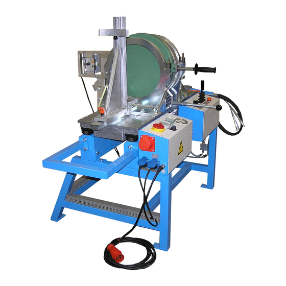
- Page 1 WIDOS Einsteinstraße 5 Phone +49 7152 9939 0 Wilhelm Dommer Söhne D-71254 Ditzingen +49 7152 9939 40 GmbH info@widos.de Internet: www.widos.de Working instructions Translation Heating element-butt welding machine WIDOS 4002 Keep for further use!
- Page 2 Order of spare parts and after sales service Address of manufacturer WIDOS Wilhelm Dommer Söhne GmbH Einsteinstr. 5 D - 71254 Ditzingen Phone: +49 7152 9939 0 Fax: +49 7152 9939 40 E-mail: info@widos.de Internet: www.widos.de 28.05.19 Working instructions WIDOS 4002 Page 2 of 47...
- Page 3 Therefore the searched information can be found easily. WIDOS 5/28/2019 Wilhelm Dommer Söhne GmbH Einsteinstraße 5 D-71254 Ditzingen All rights reserved. Reprinting only allowed with permission of the corporation. Any changes are subject to technical innovations. 28.05.19 Working instructions WIDOS 4002 Page 3 of 47...
-
Page 4: Table Of Contents
1.3. Conformity ..........................7 1.4. Marking of the product ......................8 1.4.1. Technical data ........................8 1.4.1.1. WIDOS 4002 general data ....................8 1.4.1.2. Heating element......................8 1.4.1.3. Planer ..........................9 1.4.1.4. Hydraulic aggregate ......................9 ... - Page 5 Welding of cross- and T-pieces ..................... 35 6.4. How to prepare pipes for T-pieces..................35 7. MAINTENANCE AND REPAIR ..................39 7.1. Planer ........................... 39 7.2. Clamping elements ........................ 39 28.05.19 Working instructions WIDOS 4002 Page 5 of 47...
- Page 6 7.7. Disposal ..........................41 7.8. Transport ..........................41 8. WIRING AND HYDRAULIC DIAGRAMS ..............42 9. SPARE PARTS LIST ....................46 10. DECLARATION OF CONFORMITY ................47 28.05.19 Working instructions WIDOS 4002 Page 6 of 47...
-
Page 7: Description Of Product
1.1. Mounting and purpose-oriented use The WIDOS 4002 is a workshop machine and especially designed for the heating element butt welding of pipes and fittings from Ø = 90 mm - 315 mm. (Standard diameters are: 90 / 110 / 125 / 140 / 160 / 180 / 200 / 225 / 250 / 280 / 315 mm). -
Page 8: Marking Of The Product
The product is marked by a type-plate at the basic machine. It contains the machine type, the serial number and the year of construction. 1.4.1. Technical data 1.4.1.1. WIDOS 4002 general data Material: PP; PE PVDF Pipe dimension: Outside-Ø = 90 – 315 mm;... -
Page 9: Planer
Max. force (F=P*A) (with 2.cylinder) 3,62 kN (at 100 bar) 9,05 kN (at 250 bar) Moving speed of the piston: ca. 5 cm/s without additional cylinder ca. 3,7 cm/s with additional cylinder 28.05.19 Working instructions WIDOS 4002 Page 9 of 47... -
Page 10: Equipment And Accessories
- Clamping tools and inserts for fabrication of T-pieces - Plane girder for planing only at one side - Reduction inserts with 15° or 22,5° (OD 63 mm…315 mm) For order numbers and single parts see spare parts list 28.05.19 Working instructions WIDOS 4002 Page 10 of 47... -
Page 11: Safety Rules
T h e a c c i d e n t p r e v e n t i o n m e a s u r e s a r e v a l i d ( U V V ) . 28.05.19 Working instructions WIDOS 4002 Page 11 of 47... -
Page 12: Obligation Of The Owner
Persons who are being instructed are only allowed to work on the machine under the supervision of an experienced person. 28.05.19 Working instructions WIDOS 4002 Page 12 of 47... -
Page 13: Dangers While Handling The Machine
2.7. Dangers while handling the machine The machine WIDOS 4002 has been constructed according to the latest standards of the technology and according to the recognized technical rules. Although, during the operation dangers for the user or for persons standing close as well as damages for items may occur. -
Page 14: Special Dangers
Transport the planer only at the grip. Do not touch the face of the planer. Keep away third persons from the swiveling area of the planer. Switch on the planer only for use. 28.05.19 Working instructions WIDOS 4002 Page 14 of 47... -
Page 15: Danger Of Stumbling Over Electric Wire And Hydraulic Hose
Machine parts which are not in perfect condition have to be replaced immediately. Only use original WIDOS spare and wear parts. In case of order, always state the machine number! 2.13. Cleaning of the machine The used materials and clothes have to be handled and disposed of properly especially ... -
Page 16: Description Of Process
After the cooling remove the additional cylinder and store it in the holder on the right side of the machine. Heating element heats the pipes up to welding temperature. Welded pipe with inside and outside bead. 28.05.19 Working instructions WIDOS 4002 Page 16 of 47... -
Page 17: Operating And Indicating Elements
- Use only if necessary. Place for stop watch - to place for the delivered stop watch giving a good view on it. Pressure gauge - Indication of the hydraulic pressure 28.05.19 Working instructions WIDOS 4002 Page 17 of 47... -
Page 18: Elements On The Right Side
- Includes the electric elements and the wirings 4.2. Elements on the right side Denomination Function Clamping lever - release in order to move the right table half, for horizontal mismatch compensation. 28.05.19 Working instructions WIDOS 4002 Page 18 of 47... -
Page 19: Elements On The Left Side
Plug box 230 V - Connection for planer Power supply 400 V - Power supply to work without the conversion kit. 4.4. Heating element controls 4.4.1. Elements on the heating element 28.05.19 Working instructions WIDOS 4002 Page 19 of 47... -
Page 20: Heating Element For Conversion Kit (Optional)
Display: ACTUAL temperature (without blinking points). Appears as soon as a temperature of > 170°C is reached and rises continuously to DESIRED temperature. The desired temperature is maintained by a certain pulse- position ratio. 28.05.19 Working instructions WIDOS 4002 Page 20 of 47... -
Page 21: Additional Cylinder (Optional)
In case you drive the machine without connected additional cylinder, then connect the cylinder to the distributor block, drive the tables and the additional cylinder entirely apart and mount the additional cylinder onto the clamping tools afterwards. 28.05.19 Working instructions WIDOS 4002 Page 21 of 47... -
Page 22: Holes In The Table
Markings have been fixed to the table for angles 11.25° and 15°, other angles must be adjusted by goniometer. Afterwards retighten screws 1 and 2. 28.05.19 Working instructions WIDOS 4002 Page 22 of 47... -
Page 23: Elements On The Planer
(A) for planing is used. Center the centering bolt of the girder in the central drill of the planer and hold tightly to the girder during planing. 28.05.19 Working instructions WIDOS 4002 Page 23 of 47... -
Page 24: Elements At The Clamping Tool
4.12. Conversion kit clamping tool (optional) Mount the small clamping tool including the base plate onto the right machine table using hexagon socket screws. Pipe bracket OD 450 mm Base plate for right clamping tool 28.05.19 Working instructions WIDOS 4002 Page 24 of 47... -
Page 25: Limit Stop Of Planer For T-Piece Welding (Optional)
Plane the pipes up to limit stop. Having finished planing, swing the limit stops out of the machine. Pan- head screw M 8x35 DIN 7984 Pan- head screw M8x30 DIN 912 and washer Limit stop 28.05.19 Working instructions WIDOS 4002 Page 25 of 47... -
Page 26: Base Plate For The Welding Of T- And Cross-Pieces 90
Mount the basic clamping tool with reduction insert 22,5° on right table (no base plate) and swivel it by 7,5°. Base plates for: T – 90°, cross 90° and T - 60° 28.05.19 Working instructions WIDOS 4002 Page 26 of 47... -
Page 27: Clamping Tools For T-Piece 90
The prepared pipes are welded in both clamping tools in the front. Third welding: Tee welded pieces from first and second weldings are clamped on both sides. Mount small Mount small clamping tools on clamping tools on the left the right 28.05.19 Working instructions WIDOS 4002 Page 27 of 47... -
Page 28: Clamping Tool For T-Piece 45
Mount the basic clamping tool with reduction insert 22,5° on the right table (no base plate). Clamp the welded piece from first welding into large clamping tools. Clamp the third prepared pipe into the right clamping tool. Basic clamping tool Reduction insert 22,5° 28.05.19 Working instructions WIDOS 4002 Page 28 of 47... -
Page 29: Clamping Tool For T - 60
7,5°. Clamp the welded piece from first welding into large clamping tools. Clamp the third prepared pipe into the right clamping tool. Basic clamping tool swiveled for 7,5° Reduction inserts 22,5° 28.05.19 Working instructions WIDOS 4002 Page 29 of 47... -
Page 30: Starting And Operating
(chapter: 4.3, no. 19 + 20), and switch the planer ready (chapter: 4.8). Take care for the ambient conditions: Welding must not be performed at direct sunlight. If necessary, use a welding umbrella. 28.05.19 Working instructions WIDOS 4002 Page 30 of 47... -
Page 31: Welding Process
Put the work pieces into the clamping tools with the same distance (appr. 20 – 30 mm) inwardly, fasten the clamping screws and align the work pieces to each other. Use the WIDOS rollerstands for the alignment of long pipe ends, for bends use the supporting angle and pipe supports. -
Page 32: Planing Of The Pipes
If you want to weld with additional cylinder, remove the cylinder from the device (chapter: 4.5). Always put the additional cylinder onto the right clamping tool. Connect the hydraulic hoses of the additional cylinder to the connections in order to start welding. 28.05.19 Working instructions WIDOS 4002 Page 32 of 47... -
Page 33: Adjusting
After completion of the cooling time release pressure, do not open the table. 5.3.9. Welding complete In case you have welded with additional cylinder, remove and store it on the holder. Open the clamping tools and remove the welded part. Open the machine. 28.05.19 Working instructions WIDOS 4002 Page 33 of 47... -
Page 34: Welding Logs And Tables
Example 1: bend of 90° 4 segments (6 welding surfaces) 90° sawing angle = ----- = 15° Example 2: bend of 45° in 3 segments (4 welding surfaces) 45° sawing angle = ----- = 11,25° 28.05.19 Working instructions WIDOS 4002 Page 34 of 47... -
Page 35: Welding Of Cross- And T-Pieces
The optional available clamping device for angles is screwed on together with the adapter plate and standard tools. T - pieces (45°, 60° and 90°) and Cross-pieces up to OD=250 mm can be welded. 6.4. How to prepare pipes for T-pieces 28.05.19 Working instructions WIDOS 4002 Page 35 of 47... - Page 36 Welding logs and tables Chapter 6 28.05.19 Working instructions WIDOS 4002 Page 36 of 47...
- Page 37 Welding logs and tables Chapter 6 28.05.19 Working instructions WIDOS 4002 Page 37 of 47...
- Page 38 Welding logs and tables Chapter 6 You can access our website and select our welding tables via the qr code shown here. Select ”WIDOS 4001-4002” and the corresponding material (PE / PP /PVDF). 28.05.19 Working instructions WIDOS 4002 Page 38 of 47...
-
Page 39: Maintenance And Repair
For machines with an especially high usage percentage the testing cycle should be shortened. The work has to be performed at the WIDOS GmbH company or by an authorized partner. In general, take care for cleanness! Handle the machine carefully. -
Page 40: How To Check The Oil Level
The linear guiding rods of the basic machine are to be kept free from dirt and to be lubricated regularly over the nipple at the linear guide. Store dry. 28.05.19 Working instructions WIDOS 4002 Page 40 of 47... -
Page 41: Disposal
If need be, dismount the planer and the heating element: For that purpose remove the heating Remove the four screws (S) from the planer element from the holder (see arrow) and then the planer itself 28.05.19 Working instructions WIDOS 4002 Page 41 of 47... -
Page 42: Wiring And Hydraulic Diagrams
WIDOS Einsteinstraße 5 Phone +49 7152 9939 0 Wilhelm Dommer Söhne D-71254 Ditzingen +49 7152 9939 40 GmbH info@widos.de Internet: www.widos.de 8. Wiring and hydraulic diagrams 28.05.19 Working instructions WIDOS 4002 Page 42 of 47... - Page 43 Wiring and hydraulic diagrams Chapter 8 28.05.19 Working instructions WIDOS 4002 Page 43 of 47...
- Page 44 Wiring and hydraulic diagrams Chapter 8 28.05.19 Working instructions WIDOS 4002 Page 44 of 47...
- Page 45 Wiring and hydraulic diagrams Chapter 8 28.05.19 Working instructions WIDOS 4002 Page 45 of 47...
-
Page 46: Spare Parts List
+49 7152 9939 40 GmbH info@widos.de Internet: www.widos.de 9. Spare parts list You can access our website and select our spare parts lists via the qr code shown here. Select “4002 manual” 28.05.19 Working instructions WIDOS 4002 Page 46 of 47... -
Page 47: Declaration Of Conformity
10. Declaration of conformity Issuing the declaration of conformity with regard to complying with the basic requirements and assembling the technical documentation is in the sole responsibility of: Manufacturer / Installation WIDOS Wilhelm Dommer Söhne GmbH company: Address: WIDOS GmbH Einsteinstr.
Need help?
Do you have a question about the 4002 and is the answer not in the manual?
Questions and answers