Table of Contents
Advertisement
Declaration of Conformity
According to 47 CFR, Parts 2 and 15 of the FCC Rules
The following designated product:
EQUIPMENT: MAINBOARD
MODEL NO.: 5AGM2
is a Class B digital device that complies with 47 CFR Parts 2 and 15 of the FCC
Rules. Operation is subject to the following two conditions:
1. This device may not cause harmful interference.
2. This device must accept any interference received, including interference
that may cause undesired operation.
This declaration is given to the manufacturer:
CHAINTECH COMPUTER U.S., INC
509 Valley Way, Milpitas, CA 95035, U.S.A.
Tel: 1-408-935-6988
Fax: 1-408-935-6989
Chaintech President: Raff Tung
Signature:
i
Advertisement
Chapters
Table of Contents

Related Manuals for CHAINTECH 5AGM2


Summary of Contents for CHAINTECH 5AGM2
- Page 1 According to 47 CFR, Parts 2 and 15 of the FCC Rules The following designated product: EQUIPMENT: MAINBOARD MODEL NO.: 5AGM2 is a Class B digital device that complies with 47 CFR Parts 2 and 15 of the FCC Rules. Operation is subject to the following two conditions: 1.
- Page 2 Federal Communications Commission Statement This device complies with FCC Rules Part 15. Operation is subject to the following two conditions: This device may not cause harmful interference This device must accept any interference received, including interference that may cause undesired operation. This equipment has been tested and found to comply with the limits for a Class B digital device, pursuant to Part 15 of the FCC Rules.
- Page 3 Main Board User's Manual...
-
Page 4: Table Of Contents
Table of Contents Chapter 1 Introduction ................. 1 Product Specifications ............1 Package Contents ..............3 Mainboard Layout ..............4 Connector and Jumper Reference Chart ........ 4 Chapter 2 Hardware Setup ..............5 Introduction to Jumpers ............5 Installing a PGA type CPU in a ZIF Socket ......6 CPU Jumper Configuration ............ - Page 5 Over-ride Power Button ................. 12 Poly-fuse Over Current Protection ............14 Memory-bus Frequency setting jumper ..........16 Flash BIOS Protection ................27 Power-On by Alarm ................31 Appendices Appendices Appendices Appendices Appendices Appendix I On Board I/O Addresses & IRQ Maps ......43 Appendix II FAN78 SMART Technology Upgrade Kit ....
- Page 6 - Memo...
-
Page 7: Chapter 1 Introduction
Introduction Chapter 1 Introduction 1-1 Product Specifications r r r r r CPU ® - Supports up to 200MHz Intel Pentium processors and up to 233MHz ® Pentium processors with MMX technology ® - Supports Intel Pentium P54CTB OverDrive processors - Supports PR166 ~ PR200 Cyrix/IBM 6x86L... - Page 8 Chapter 1 r r r r r Boot Block Flash BIOS - Award System BIOS supports PnP, APM, DMI & multi-device booting such as SCSI HDD, IDE HDD, CD-ROM, LS120, ZIP-ATAPI,etc. - Includes Trend ChipAway Virus for a virus-free system boot-up r r r r r On Board Ultra I/O Functions - ITE 8661 I/O chip - One floppy disk drive connector supports up to 2.88MB, Japanese 3 Mode,...
-
Page 9: Package Contents
Introduction 1-2 Package Contents This product comes with the following components: r One mainboard r One 9-pin serial port and 25-pin parallel port ribbon cable with bracket (Figure 1-1) r One 25-pin serial port ribbon cable with bracket (Figure 1-2) r One 40-pin IDE connector ribbon cable (Figure 1-3) r One 34-pin floppy disk drive ribbon cable (Figure 1-4a) or (Figure 1-4b) r Optional USB kit with PS/2 mouse, infrared and two USB ports (Figure 1-5) -
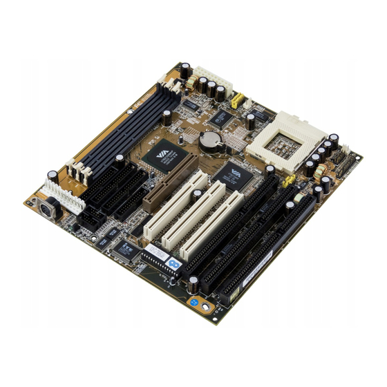
Page 10: Mainboard Layout
Chapter 1 1-3 Mainboard Layout 1-4 Jumper and Connector Reference Page Chart Jumper & Function Page Connector No. AT/ATX power supply jumper Clear CMOS data jumper CPU voltage jumpers JP5-7 System frequency jumpers JP8-10 System frequency ratio jumpers JP11 Memory-bus frequency setting jumper AT Power supply connector PS/2 mouse, USB, infrared connector PS/2 mouse connector... -
Page 11: Chapter 2 Hardware Setup
Hardware Setup Chapter 2 Hardware Setup If your mainboard has already been installed in your computer you may still need to refer to this chapter if you plan to upgrade your system's hardware. Be sure to disconnect the power cable from the power source before performing any work on your mainboard, i. -
Page 12: Installing A Pga Type Cpu In A Zif Socket
Chapter 2 2-2 Installing a PGA type CPU in a ZIF Socket The Intel Socket 7, designed for the Pentium processor, has been incorporated as a standard mainboard specification and is compatible with AMD and Cyrix CPUs. To insert your CPU into Socket 7 please do the following: 1. -
Page 13: Cpu Jumper Configuration
Hardware Setup 2-3 CPU Jumper Configuration Frequency Configuration If you install a CPU on this mainboard, you must set JP 5-7 for System Frequency and JP 8-10 for CPU Bus Frequency Ratio. See Figure 2-4 CPU/System Frequency Jumper Settings. CPU Bus Frequency & Frequency Ratio Configuration * CPU Speed = Frequency ratio x System Frequency JP5~JP7 JP8~JP10... -
Page 14: Jp4 Cpu Voltage Jumpers
Chapter 2 Overclocking Operating a CPU at a higher frequency than its specification allows is called overclocking. If the CPU frequency is set at a higher frequency than its specification allows, it may or may not run at that freqency, depending on the quality of the CPU and the extent to which the the frequency has been overset. - Page 15 Hardware Setup CPU Power Voltage System freq. Freq. ratio CPU-type JP5~JP7 Speed rate JP8~JP10 I/O Vcc Core Vcc P54C-133 x2.5 P54C-166 P54C-200 Pentium Intel w/MMX x2.5 @166MHz Pentium w/MMX @200MHz Pentium w/MMX x3.5 @233MHz 6x86-PR166 @133MHz 6x86-PR200 @150MHz 6x86L-PR166 @133MHz 6x86L-PR200 @150MHz 6x86MX-PR166...
-
Page 16: Connector And Jumper Settings
Chapter 2 2-4 Connector and Jumper Settings Connectors are used to link the system board with other parts of the system, including the power supply, the keyboard, and the various controllers on the front panel of the system case. The power supply connector is the last connection to be made while installing a mainboard. -
Page 17: Feature Explanations Software Power-Off Control
Hardware Setup Software Power-Off Control This mainboard can be powered down using theWindows 95 Software Power-Off function. To power down your computer, click the START button on the Windows 95 task bar. Select "Shut Down The Computer" and the system turns off. The message "It is now safe to turn off your computer"... -
Page 18: Over-Ride Power Button
Chapter 2 Front Panel Connector Set (CN5) A through G A. Over-ride Power Button Connector The power button on the ATX chassis can be used as a normal power switch as well as a button to activate Advanced Power Management Suspend mode. This mode is used for saving electricity when the computer is not in use for long periods of time. -
Page 19: Speaker Connector
Hardware Setup C. Green Switch/Green LED Connector Some ATX cases provide a Green switch which is used to put the system in Suspend mode. In suspend mode, the power supply to the system is reduced to a trickle, the CPU clock is stopped, and the CPU core is in it's minimum power state. -
Page 20: Poly-Fuse Over Current Protection
Chapter 2 AT Keyboard Connector Definition Keyboard Clock Keyboard Data (None) Ground +5V DC Keyboard Connector/Pin Definitions Poly-fuse Over Current Protection The poly-fuse protects the system from dangerous voltages the system might be exposed to via the keyboard or USB connectors. In case of such exposure, the poly- fuse will immediately be disconnected from the circuit, just like a normal fuse. -
Page 21: Ps/2 Mouse Connector
Hardware Setup B. PS/2 Mouse Connector If a PS/2 mouse is used, BIOS will automatically detect and assign IRQ12. Definition Data Not Connected Ground +5V (fused) Clock Not Connected C. Dual Channel USB(Universal Serial Bus) Connector Enable the OnChip USB function in BIOS's Integrated Peripherals Menu if you want to use a USB keyboard. -
Page 22: Main Memory Configuration
Chapter 2 2-6 Main Memory Configuration The DRAM memory system on board consists of 3 banks, and the memory range is 8 ~ 384 MBytes. Memory-bus Frequency Setting Jumper (JP11) This setting is only relevant when SDRAM-DIMM is used. 1~2 short (default): Synchronous mode Memory-bus speed = CPU-bus speed 2~3 short: Asynchronous mode Memory-bus speed = AGP-bus speed... - Page 23 Hardware Setup Because 128MB DIMM is not yet mainstream, the compatibility of 128MB DIMM can not be 100% guaranteed. This mainboard supports 3.3v, unbuffered, 4-clock, SDRAM DIMM only. Buffered, 5V, or 2-clock SDRAM DIMMs should not be used. This board has DIMM (Dual-in-line Memory Module) sockets to support SDRAM type DRAM and has the better optimized read timings (7-1-1-1).
- Page 24 Chapter 2 - Memo...
-
Page 25: Chapter 3 Award Bios Setup Program
Award BIOS Setup Program Chapter 3 Award BIOS Setup Program Award's BIOS ROM has a built-in setup program that allows users to modify the basic system configuration. This information is stored in CMOS RAM so that it can retain the setup information, even when the power is turned off. When you turn on or reboot the system, press the Delete key to enter the Award BIOS setup program. -
Page 26: Standard Cmos Setup
Chapter 3 3-1 Standard CMOS Setup The Standard CMOS Setup allows users to configure system components such as hard disk drive, floppy disk drive and video display as well as date, time and boot- up error signaling. This configuration menu should be changed when installing a mainboard for the first time, changing hardware in your system such as the HDD, FDD, video display, or when the CMOS data has been lost or contaminated. - Page 27 Award BIOS Setup Program Type (Auto/User/None): Use the fields under the Type column to determine the method you will use to configure the IDE devices. If you choose Auto, BIOS will automatically detect and make optimal settings for most IDE hard drives. The mainboard manufacturer recommends that you choose Auto for all drives.
- Page 28 Chapter 3 the LBA setting. Large mode is not supported by all operating systems, i.e., only certain versions of DOS support large mode. LBA - (Large/Logical Block Addressing) With LBA, the IDE controller transforms the data address described by sector, head, and cylinder number into a physical block address, significantly improving data transfer rates.
-
Page 29: Bios Features Setup
Award BIOS Setup Program 3-2 BIOS Features Setup By choosing the BIOS Features Setup option from the CMOS Setup Utility menu (Figure 3-1), the screen below is displayed. This sample screen contains the manufacturer's default values for the mainboard. ROM PCI / ISA BIOS (2A5LEC39) BIOS FEATURES SETUP AWARD SOFTWARE, INC. - Page 30 Chapter 3 2 external cache. Both settings are left enabled to significantly increase the performance of your computer. C. BOOT UP FEATURES After turning on the system, BIOS will perform a series of device initializations and diagnostic tests discussed below. Quick Power On Self Test (POST) Enable this function to reduce the amount of time required to run the POST (Power On Self Test).
- Page 31 Award BIOS Setup Program Typematic Rate (Chars/Sec) The typematic rate sets the rate at which characters on the screen repeat when a key is pressed and held down. Typematic Delay (Msec) The typematic delay sets how long after you press a key that a character begins repeating.
-
Page 32: Chipset Features Setup
Chapter 3 3-3 Chipset Features Setup By choosing the Chipset Features Setup option from the CMOS Setup Utility menu (Figure 3-1), the screen below is displayed. This sample screen contains the manufacturer's default values for the mainboard. ROM PCI / ISA BIOS (2A5LEC39) CHIPSET FEATURES SETUP AWARD SOFTWARE, INC. -
Page 33: Flash Bios Protection
Award BIOS Setup Program C. System BIOS Cacheable Enabling this function allows caching of the system BIOS ROM at F0000h- FFFFFh, resulting in better system performance. However, if any program writes to this memory area, a system error may result. Caching the system BIOS results in better performance than shadowing the system BIOS as discussed in Section 3-2. -
Page 34: Power Management Setup
Chapter 3 3-4 Power Management Setup This section provides information on the Green PC power management funtcions. In order to enable the power management functions, please select the Power Management Setup option from the CMOS Setup Utility menu (Figure 3-1). This sample screen contains the manufacturer's default values for the mainboard. - Page 35 Award BIOS Setup Program below. For a description of the power saving modes (Doze, Standby, and Suspend) see their descriptions below. Disabled - Turns off the Power Management functions. Max. Saving - All timers are set at the minimum value of one minute to maximize power saving.
- Page 36 Chapter 3 selected Blank. This function serves as both a screen saver and an electricity saver. DPMS Supported - Select this option if your video card supports the Display Power Management Signaling (DPMS) standard (i.e., you have a monitor that supports Green features).
-
Page 37: Power-On By Alarm
Award BIOS Setup Program J. Power On By Modem When enabled, a modem that receives a call will wake up the system from Soft- off or Green mode. To activate this function, you must leave your modem on and use the Software Power off. See the Software Power-Off control description in Section 2-4 of this manual. -
Page 38: Pnp/Pci Configuration
Chapter 3 3-5 PNP/PCI Configuration This section provides IRQ and DMA setting information. By choosing the PnP/PCI Configuration option from the CMOS Setup Utility menu (Figure 3-1), the screen below is displayed. This sample screen contains the manufacturer's default values for the mainboard. - Page 39 Award BIOS Setup Program C. Reset Configuration Data When Enabled the system BIOS will clear/reset the ESCD during POST. After clearing the ESCD, the BIOS will then change this item's value to "Disabled." Otherwise, the ESCD data would become useless. D.
-
Page 40: Load Setup Defaults
Chapter 3 3-6 Load Setup Defaults Load Setup Defaults loads the default system values directly from the CMOS Setup Utility menu (Figure3-1). If the stored record created by the setup program becomes corrupted and therefore unusable, these defaults will be loaded automatically when you turn on the computer. -
Page 41: Integrated Peripherals
Award BIOS Setup Program 3-7 Integrated Peripherals This section provides information on setting peripheral devices. By choosing the Integrated Peripherals option from the CMOS Setup Utility menu (Figure 3-1), the screen below is displayed. This sample screen contains the manufacturer's default values for the mainboard. - Page 42 Chapter 3 D. On Board IDE Control The following settings are used to configure the on-board IDE controller. IDE Primary/Secondary Master/Slave PIO/UDMA The four IDE PIO (programmed Input/Output) fields let you set a PIO mode (0-4) for each IDE device that the internal PCI IDE interface supports. Modes 0 through 4 provide successively increased performance.
-
Page 43: Supervisor Password & User Password Setting
Award BIOS Setup Program 3-8 Supervisor Password & User Password Setting There are four different variables that control password settings. The first two are located under the Security Option function in BIOS Features Setup Menu (Figure 3-3). When the Security Option function is set to Setup, a password is required to enter BIOS and change BIOS settings. - Page 44 Chapter 3 B. Set Both Supervisor Password and User Password Figure 3-10 Set Both Supervisor and User Password...
-
Page 45: Ide Hdd Auto Detection
Award BIOS Setup Program 3-9 IDE HDD Auto Detection This utility can automatically detect IDE hard disk type and parameters. The detection process take about 5 seconds for each physical drive. After the utility detects the disk drive, type Y and press [Enter] to automatically load the parameters in the Hard Disk section of the Standard CMOS Setup menu. - Page 46 Chapter 3 - Memo...
-
Page 47: Chapter 4 Mainboard Software Guide
Mainboard Software Chapter 4 Mainboard Software Guide The Mainboard Software Guide is found on the CD-ROM that is enclosed with your mainboard and is a PDF file which must be viewed with Adobe's freeware ® called Acrobat Reader. The Acrobat Reader software is also included on the same CD-ROM. - Page 48 Chapter 4 - Memo...
-
Page 49: Appendix I On Board I/O Addresses & Irq Maps
Introduction Appendix I On Board I/O Addresses & IRQ Maps System Resource I/O Address 1. Timer IRQ0 040, 043 2. Keyboard IRQ1 060, 064 3. Programmable INT IRQ2 0020, 0021, 00A0, 00A1 4. COM2(B) IRQ3 2F8, 2FF 5. COM1(A) IRQ4 3F8, 3FF 6. - Page 50 User's Manual - Memo...
-
Page 51: Appendix Ii Fan78 Smart Technology Upgrade Kit
Appendix II FAN78- SMART Technology Upgrade Kit FAN78 System Monitor Software for Win95 The FAN78 upgrade kit provides a PC self-dialogistic capability called the SMART (System Monitoring and Alerting) technology. Features - Detects four on-board voltages (CPU Core Voltage, 3.3V, 5V, 12V) - Two fan speed sensing - One precise CPU temperature sensor and one chassis temperature sensor - Four types of speaker-driver signal output... - Page 52 - Memo...
Need help?
Do you have a question about the 5AGM2 and is the answer not in the manual?
Questions and answers