Table of Contents
Advertisement
Advertisement
Table of Contents

Related Manuals for CHAINTECH VNF4/Ultra


Summary of Contents for CHAINTECH VNF4/Ultra
- Page 1 CHAINTECH VNF4/Ultra NVIDIA nForce4/Ultra ATX Motherboard User’s Guide...
-
Page 2: Declaration Of Conformity
According to 47 CFR, Parts 2 and 15 of the FCC Rules The following designated product: EQUIPMENT: MAINBOARD MODEL NO.: VNF4/Ultra is a Class B digital device that complies with 47 CFR Parts 2 and 15 of the FCC Rules. Operation is subject to the following two conditions: 1. -
Page 3: Federal Communications Commission Statement
Federal Communications Commission Statement This device complies with FCC Rules Part 15. Operation is subject to the following two conditions: * This device may not cause harmful interference. * This device must accept any interference received, including interference that may cause undesired operation. This equipment has been tested and found to comply with the limits for a Class B digital device, pursuant to Part 15 of the FCC Rules. -
Page 4: Table Of Contents
CHAPTER 1 INTRODUCTION...................... 1 1-1 S ........................1 PECIFICATIONS 1-2 B & F ......................3 ENEFITS EATURES 1-3 P ......................... 5 ACKAGE ONTENTS 1-4 L ........................... 6 AYOUT CHAPTER 2 HARDWARE......................7 2-1 PC D.I.Y. A ..................7 SSEMBLY NSTRUCTIONS 2-2 J .......................... - Page 5 3-25 S CMOS S CMOS S )............24 TANDARD ETUP ETUP DU TANDARD 3-26 A BIOS F BIOS) ........25 DVANCED EATURES ONCTIONNALITÉS VANCÉES DU 3-27 A )......25 DVANCED HIPSET EATURES ONCTIONNALITÉS VANCÉES DU HIPSET 3-28 I ....................25 NTEGRATED ERIPHERALS ’A...
-
Page 6: Revision History
ПРАВЛЕНИЕ ЧАСТОТОЙ НАПРЯЖЕНИЕМ 3-58 F (У )......34 REQUENCY OLTAGE ONTROL 3-59 L (З АГРУЗИТЬ БЕЗОПАСНЫЕ НАСТРОЙКИ ПО УМОЛЧАНИЮ ) ... 34 EFAULTS 3-60 L (З АГРУЗИТЬ ОПТИМИЗИРОВАННЫЕ НАСТРОЙКИ ПО УМОЛЧАНИЮ PTIMIZED EFAULTS ..............................34 СТАНОВКА ПАРОЛЯ АДМИНИСТРАТОРА 3-61 S &... -
Page 7: Chapter 1 Introduction
Chapter 1 Chapter 1 Introduction 1-1 Specifications Supports AMD Socket-939 Athlon 64 FX / Athlon 64 Processor interface via 2000MT/s Hyper Transport bus Chipset NVIDIA nForce4 (VNF4) / nForce4 Ultra (VNF4 Ultra) Memory Four 184- pin DDR DIMMs up to 4GB Supports Dual Channel DDR266/333/400 memory Expansion Slots One PCI Express x16 port for PCI Express graphics card... - Page 8 Chapter 1 NVIDIA ActiveArmor (VNF4 Ultra) A dedicated secure networking engine enhances networking security while reducing CPU overhead Specialized features defend against spyware intrusions and hacker attacks An intelligent application manager alerts you when unknown applications attempt to access the network Supports the new Microsoft networking architecture for fast and secure networking Boot-Block Flash ROM...
-
Page 9: Benefits & Features
Chapter 1 1-2 Benefits & Features NVIDIA nForce4/nForce4 Ultra chipset PCI Express Support Designed to run perfectly with the next-generation PCI Express bus architecture. This new bus doubles the bandwidth of the AGP 8X bus, delivering over 4 GB per second in both upstream and downstream data transfers. NVIDIA nTune Performance Application Enables the easiest, safest, and highest performing overclocking available for NVIDIA nForce-based PCs. - Page 10 Chapter 1 Unified Driver Architecture (UDA) Part of the NVIDIA Forceware unified software environment (USE). The NVIDIA UDA guarantees forward and backward compatibility with software drivers. Simplifies upgrading to a new NVIDIA product because all NVIDIA products work with the same driver software. HyperTransport Technology A state of the art I/O bus interface, delivering the highest continuous throughput—800MB/s—between the nForce platform processors.
-
Page 11: Package Contents
Chapter 1 1-3 Package Contents 1. 1x IDE cable 2. 1x FDD cable 3. 2x SATA2 cable 4. 1x Power cable 5. 1x I/O shield 6. 1x Grease 7. 1x Manual 8. 1x Support driver CD 9. 1x Value Pack 2005 Note: If any of the foregoing objects is missing when you unpack the motherboard package, please contact your retailer immediately. -
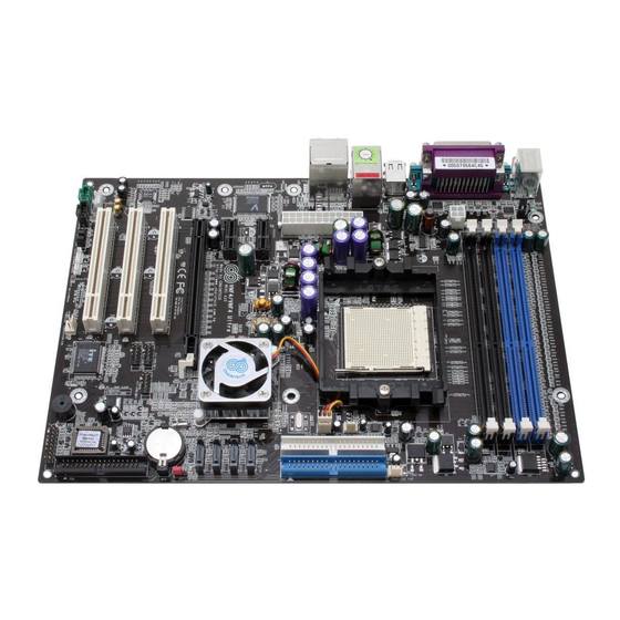
Page 12: Layout
Chapter 1 1-4 Layout... -
Page 13: Chapter 2 Hardware
Chapter 2 Chapter 2 Hardware 2-1 PC D.I.Y. Assembly Instructions 1. Jumper Setting: Set the CPU External Clock, Frequency Ratio and the CPU voltage according to the instruction printed on the manual or silkscreen printed on the mainboard. 2. Installing FDD and IDE devices: Aligned the red colored edge of the cable with the pin 1 of the drive connector on the mainboard and gently attached it. - Page 14 Chapter 2 Due to CPU specifications limitation, two DDR400 memory modules inserted into DIMM1/3, three DDR400 into DIMM1/2/3, or four DDR400 into DIMM1/2/3/4 is not recommended. 5. Mounting a Mainboard into a Chassis: Use standoffs and screws to securely mount the mainboard and make sure that all the mounting holes are properly screwed.
-
Page 15: Jumpers
Chapter 2 2-2 Jumpers JP1 (CMOS Clear Jumper): Definition Normal (default) Clear CMOS Data There is a CMOS RAM chip on board that has power from external battery to retain the data and system configuration. To clear the contents of the CMOS, please follow the steps below. -
Page 16: Connectors
Chapter 2 JP6/6A (USB Power On) Definition Disable Enable A USB keyboard hot key or a USB mouse-click can activate this motherboard. To use this function, select a hot key of your choice at the USB Resume from S3 option under Wake Up Events in the BIOS's Power On Management screen. - Page 17 Chapter 2 8. Line-Out port. The green port is used to connect the audio devices such as the headphone or speaker. 9. Microphone port. The pink port is used to connect the microphone. 10. Side Speaker-Out port. The black port is used to connect the side speakers in the 8-channel audio configuration 11.
- Page 18 Chapter 2 FD1 (Floppy Connector): This motherboard provides a standard floppy disk drive connector that supports 360K, 720K, 1.2M, 1.44M and 2.88M floppy disk types. It is connected to a floppy disk drive using 34 pins. SATA 1/2/3/4 (Serial ATA Connector): This motherboard comes with 4 Serial ATA connectors that can be connected to the ATA 1.5GB/S (VNF4) or ATA2 3.0GB/S (VNF4 Ultra).
- Page 19 Chapter 2 FAN1/2/3/4 (CPU/System/ Case Fan /Chip Fan Connectors): This motherboard's hardware management is able to detect the CPU and system fan speed in rpm (revolutions per minute). The wiring and plugging may vary depending on the manufacturer. On standard fans, the red is positive (+12V), the black is ground, and the yellow wire is the rotation signal.
- Page 20 Chapter 2 CN24 (Front Audio Connector): This connector gives you the option of a front-panel audio-jack cable to be plugged into a case supporting front panel audio. Remove the two jumper caps at pins [5-6] and [9-10] then plug it into the (optional) cable connector.
- Page 21 Chapter 2 2. P-LED (Power LED Connector): The power indicator LED shows the system's power status. It is important to pay attention to the correct cable and pin orientation (i.e. Be careful not to reverse the order of these two connectors.) G-BTN (Green Button Switch): Some ATX cases provide a Green button switch, which is used to put the system in Suspend mode.
- Page 22 Chapter 2 CN3 (AUX-IN): The connector is responsible for connecting devices such as the TV tuner, CD-ROM or MPEG card to receive sound signals. CN5 [WOL (Wake-on-LAN) Connector]: Enable Wake On LAN in the BIOS's Power Management Menu to use this function. The capability to remotely manage PCs over networks is a significant factor in reducing administrative and ownership costs.
- Page 23 Chapter 2 CN5A [WOM (Wake-on-Modem) Connector]: Enable the Wake On Modem selection in the BIOS's Power Management Menu to activate this function. This header is used to connect an add-in modem card, which provides WOM function to the motherboard. PCI-Express slots: PCI-E X16 & PCI-E1/ PCI-E2 PCI-E x16 slots are for installing PCI-Express graphics cards.
-
Page 24: Chapter 3 Bios Setup Program
Chapter 3 Chapter 3 BIOS Setup Program Phoenix-Award BIOS ROM has a built-in setup program that allows users to modify the basic system configuration. This information is stored in CMOS RAM so that it can retain the setup information even when the power is turned off. Press [Delete] when you Power on or Reboot the computer system. -
Page 25: Advanced Bios Features
Chapter 3 3-2 Advanced BIOS Features The motherboard manufacturer determines all of these settings. The default values should not be modified unless necessary. 3-3 Advanced Chipset Features The motherboard manufacturer determines all of these settings. The default values should not be modified unless necessary. All of the above settings have been determined by the motherboard manufacturer and should not be changed unless you are absolutely sure of what you are doing. -
Page 26: Load Fail-Safe Defaults
Chapter 3 3-9 Load Fail-Safe Defaults Load Fail-Safe Defaults loads the default BIOS values directly from the CMOS Setup Utility menu (Figure3-1). If user-defined BIOS settings are corrupted and therefore unusable, these defaults will be loaded automatically when you turn on the computer. -
Page 27: Bios 設定 (Chinese)
Chapter 3 BIOS 設定 (Chinese) Phoenix-Award BIOS ROM 可讓使用者修改 BIOS 設定,並將所有設定的資料都 儲存在 CMOS ROM 裏面。 在您電腦開機時,請按 [Delete] 進入 Phoenix-Award BIOS 的設定項目。圖 3-10 是主畫面選單,以鍵盤選擇您要修改的項目並按下[Enter],就可進行更改。畫面 下方有畫面的操作指令。當您選擇較特殊的功能時,畫面右方會提供協助資訊供 您參考。 圖 3-10 3-14 基本 CMOS 設定 基本 CMOS 的設定,可讓使用者自行設定系統的各項硬體,如軟碟機、硬碟機、 顯示卡和日期、時間。當您第一次安裝主機板、更換硬體或當 CMOS 資料遺失時, 需要設定這些資料。 3-15 進階晶片組的設定 從... -
Page 28: 內建周邊裝置設定
Chapter 3 3-16 內建周邊裝置設定 這個章節提供周邊裝置設定的資訊。(在 CMOS 的主選單中,選取[Integrated Peripherals]) 這些功能由製造商設定,除非必要,請維持在預設值。 3-17 電 源 管 理 設 定 這個章節提供了電源管理的功能設定。在 CMOS 的主選單中,選取[Power Management Setup]。這些功能由製造商設定,除非必要。請維持在預設值。 3-18 電腦狀態 CMOS 的主選單中,選取[PC Health Status]。提供目前系統溫度和電壓、CPU 的風扇轉速和系統風扇轉速的資訊。 3-19 電 壓 頻 率 的 控 制 CMOS 的主選單中,選取[Frequency/Voltage Control]。這些功能由製造商設定, 除非必要,請維持在預設值。 3-20 載入原始設定... -
Page 29: 存 檔 或 離 開 設 定
Chapter 3 第三 、 第四種是系統管理者密碼和使用者密碼的安全設定,可在 BIOS 的設定 清單中,直接選取。此主要目地是爲了分隔使用者和系統管理者的許可權,只允 許系統管理者能進入所有的修改設定。而使用者只允許修改電腦的作業系統,和 修改自己設定的 BIOS 功能選項 。 若沒有設定系統管理人的密碼,則使用者密碼,就可設定全部的功能選項。 3-23 存 檔 或 離 開 設 定 若您在此選項中,選擇[Y] (即 Yes),然後再按 [Enter] 鍵,則會將您新的設定, 存入到 BIOS 中。 3-24 離 開 不 存 檔 若您在此選項中,選擇[Y] (即 Yes),然後再按 [Enter] 鍵,則會將您新的設定, 存入到... -
Page 30: Programme Setup Du Bios (French)
Chapter 3 Programme Setup du BIOS (French) La ROM du BIOS Award Phoenix possède un programme d’installation intégré permettant aux utilisateurs de modifier la configuration de base du système. Cette information est stockée dans la RAM CMOS de sorte qu’elle peut conserver les informations de paramétrage, même quand l’alimentation est coupée. -
Page 31: Advanced Bios Features (Fonctionnalités Avancées Du Bios)
Chapter 3 3-26 Advanced BIOS Features (Fonctionnalités Avancées du BIOS) En choisissant l’option “Advanced BIOS Features” dans le menu “CMOS Setup Utility”, l’écran suivant s’affichera. Cet écran exemple contient les valeurs par défaut du fabricant pour la carte mère. 3-27 Advanced Chipset Features (Fonctionnalités Avancées du Chipset) En choisissant l’option [Advanced Chipset Features] dans le menu “CMOS Setup Utility”, l’écran suivant s’affichera. -
Page 32: Pc Health Status
Chapter 3 3-31 PC Health Status En choisissant l’option “PC Health Status” dans le menu “CMOS Setup Utility”, l’écran suivant s’affichera. Ce champ vous montre l’entrée de température/ voltages externes du système actuel et le VENTILATEUR DU CPU actuel et la vitesse de fonctionnement du VENTILATEUR du système. -
Page 33: Save And Exit Setup (Enregistrer Et Quitter Le Menu Setup)
Chapter 3 L’utilisateur, d’un autre côté, est uniquement autorisé à paramètres du BIOS. accéder au système d’exploitation de l’ordinateur et de modifier le mot de passe de l’utilisateur dans le BIOS. Remarque: quand il n’y a aucun mot de passe superviseur paramétré, le mot de passe utilisateur contrôle l’accès à... -
Page 34: Bios Setup Program (German)
Chapter 3 BIOS Setup Program (German) Phoenix-Award BIOS ROM verfügt über ein integriertes Setup-Programm, mit dem Benutzer die grundlegende Systemkonfiguration ändern können. Diese Informationen werden im CMOS RAM abgelegt, so dass die Setup-Informationen auch nach dem Abschalten erhalten bleiben. Um das Phoenix-Award BIOS Setup-Programm aufzurufen, drücken Sie [Delete] nach dem Einschalten oder nach dem Neustart des Computersystems. -
Page 35: Advanced Bios Features(Erweiterte Bios Funktionen)
Chapter 3 3-39 Advanced BIOS Features(Erweiterte BIOS Funktionen) Wenn Sie die Advanced BIOS Features-Option aus dem CMOS Setup Utility-Menü wählen, wird nachstehend gezeigte Bildschirm angezeigt. Dieser Beispielbildschirm zeigt die Standardangaben des Herstellers zum Mainboard. 3-40 Advanced Chipset Features(Erweiterte Chipsatz Funktionen) Wenn Sie die [Advanced Chipset Features]-Option aus dem CMOS Setup Utility-Menü... -
Page 36: Pc Health Status(Pc Gesundheitszustand)
Chapter 3 3-44 PC Health Status(PC Gesundheitszustand) Wenn Sie die PC Health Status-Option aus dem CMOS Setup Utility-Menü wählen, wird der nachstehend gezeigte Bildschirm angezeigt. Dieser Bildschirm zeigt Ihnen die aktuellen Systemtemperaturen externen Spannungen aktuellen Geschwindigkeiten von CPU FAN und System FAN. 3-45 Frequency/Voltage Control(Frequenz/Spannungs Einstellung) Wenn Sie die Frequency/Voltage Control-Option aus dem CMOS Setup Utility-Menü... -
Page 37: Save And Exit Setup(Speichern Und Setup Verlassen)
Chapter 3 Einstellungen im BIOS zu ändern. Der Nutzer hat nur Zugriff auf das Betriebssystem des Computers, und er kann das Nutzer-Paßwort im BIOS ändern. Hinweis: Wenn kein Supervisor-Paßwort eingerichtet wurde, ermöglicht auch das Nutzer-Paßwort den Zugriff auf alle BIOS-Einstellungen. 3-49 Save and Exit Setup(Speichern und Setup verlassen) Wenn Sie diese Option wählen, [Y] (Ja) eingeben und mit [Enter] bestätigen, werden die in den Setup-Utilitys eingegebenen Werte im CMOS-Speicher des BIOS-Chips... -
Page 38: Программа Настройки Bios (Russian)
Chapter 3 Программа настройки BIOS (Russian) Phoenix-Award BIOS ROM имеет встроенную программу настройки, которая позволяет пользователям вносить изменения в базовую конфигурацию системы. Эта информация записывается в CMOS RAM таким образом, что данные настройки сохраняются даже при отключении питания. Для входа в программу настройки Phoenix-Award BIOS нажмите на клавишу [Delete], включаете... -
Page 39: Advanced Bios Features (Расширенные Возможности Bios)
Chapter 3 3-52 Advanced BIOS Features (Расширенные возможности BIOS) При выборе раздела «Advanced BIOS Features» из меню «CMOS Setup Utility» (Утилиты настройки CMOS), появляется нижеприведенный экран. Этот пример экрана содержит настройки производителя по умолчанию для системной платы. 3-53 Advanced Chipset Features (Расширенные настройки набора микросхем) При... -
Page 40: Pc Health Status (Состояние Здоровья Пк)
Chapter 3 3-57 PC Health Status (Состояние здоровья ПК) При выборе раздела «PC Health Status» из меню Утилиты настройки CMOS (CMOS Setup Utility) , появляется следующий экран. Это поле показывает Вам текущие системные температуру/напряжения питания, текущие скорости вращения вентиляторов ЦП и системного блока. 3-58 Frequency/Voltage Control (Управление... -
Page 41: Save And Exit Setup (Сохранить И Выйти)
Chapter 3 диске.Третья и четвертая переменные - это пароль пользователя и пароль супервизора, установленные в BIOS (Рис. 2-1). Главная цель разделения пользователя и супервизора заключается в предоставлении только супервизору контроля над всеми настройками BIOS. С другой стороны, пользователю разрешается лишь доступ к операционной системе компьютера и к изменению пароля... -
Page 42: Bios 설정 프로그램 (Korean)
Chapter 3 BIOS 설정 프로그램 (Korean) ROM 은 내장 설정 프로그램을 가지고 있어 사용자로 하여금 Phoenix-Award BIOS 기본 시스템 환경 설정을 수정할 수 있게 합니다. 이 정보는 CMOS RAM 에 저장되어 전원이 꺼졌을 때도 설정 정보를 유지할 수 있도록 합니다. [Delete 사용자가... -
Page 43: Bios 기능 설정
Chapter 3 3-65 BIOS 기능 설정 에서 를 선택하면,아래 Standard CMOS Features menus Advanced BIOS Features 화면이 나타납니다. 아래의 샘플 화면에는 메인보드 제조회사의 기본 값을 담고 있습니다. 3-66 Chipset 기능설정 에서 옵션을 선택하면 Standard CMOS Features Menu [Advanced Chipset Features] 아래와... -
Page 44: 안정된 설정 불러오기
Chapter 3 3-72 안정된 설정 불러오기 CMOS Setup Utility menu 에서 Load Fail-Safe Defaults 는 기본 바이오스 값을 직접적으로 로드합니다. 설정 프로그램에 의해 만들어진 저장된 기록이 변조되고 따라서 사용불가능 하게 되면, 컴퓨터를 켰을 때 이런 기본 값이 자동으로 로드됩니다. 3-73 최적화된 설정 불러오기 CMOS Setup Utility menu 에서... -
Page 45: Chapter 4 Software
Chapter 4 Chapter 4 Software The support driver CD that comes with the motherboard provides you with certain powerful drivers and certain remarkable software, such as the latest NV Firewall, to enhance the functions of your system. To start to install the driver CD, please do the following instructions. How it works 1. - Page 46 Chapter 4 How it works 1.Click Nvidia Chipset Driver in the figure above then the figure below shall pop up and click Next>. 2.Installing all of the three drivers is recommended, then click Next>.
- Page 47 Chapter 4 3.The figure below illustrates Nvidia IDE SW driver. Click Next> after your study. 4.Clicking Yes is recommended. 5.Clicking Yes is recommended.
- Page 48 Chapter 4 6.Click Next> to install Nvidia ForceWare Network Access Manager. 7.Choose which type of setup you want to install, then click Next>.
- Page 49 Chapter 4 8.Clicking Yes is recommended. 9.Click Finish to restart your computer. 10.Once you restart the computer, the NVIDIA Firewall window as shown below shall automatically show up. To learn how to use it to secure the network security, please visit the website: http://www.nvidia.com/page/home for more detailed intelligence.
- Page 50 Chapter 4 DirecX 9.0c Install To install DireX 9.0c Install, please follow the instructions below. How it works 1.Click DirecX 9.0c Install to enter the figure below, select I accept the agreement after your study of license agreement, then click Next>.
- Page 51 Chapter 4 2.Click Next> to proceed. 3.Click Finish to restart computer.
- Page 52 Chapter 4 Realtek Codec Audio Driver The item is responsible for installing Realtek Codec Audio controller and application. To install this, please follow the instructions below. How it works 1.Click Realtek Codec Audio Driver to enter the figure below, then click Next> to continue.
- Page 53 Chapter 4 3.Select Yes, I want to restart my computer now then click Finish. nTune Utility To install this, please follow the instructions below. How it works 1.Click Next> to proceed.
- Page 54 Chapter 4 2.Click Yes after your study of license agreement. 3.Click Next> to proceed.
- Page 55 Chapter 4 4.Click Finish to complete the process.
-
Page 56: Appendix
Appendix Appendix A-1 Installing Windows 2000/XP on a SATA drive Windows 2000: (for the version 3.6 of driver) Copy the SATA drivers from the driver CD. (CDROM: Chipset\Nvidia\Nf4\Win2k_xp\Ide\Win2k→copy all the files except for the Directory "raidtool") into a floppy disk When the message "Press F6 if you need to install a third party SCSI or RAID driver"... -
Page 57: Note
Note NOTE All rights are reserved for the products and corporate names/logos that appear in this manual to their original owners. WE reserve all rights to change this manual. All information is subject to change without notice. - Page 58 How To Contact CHAINTECH How To Contact CHAINTECH Please do not hesitate to contact us if you have any problem about our products. Any opinion will be appreciated. <Headquarter> For France, Europe: For Asia, Africa, Australia and Pacific AELT COMPUTER...
Need help?
Do you have a question about the VNF4/Ultra and is the answer not in the manual?
Questions and answers