Table of Contents
Advertisement
Declaration of Conformity
According to 47 CFR, Parts 2 and 15 of the FCC Rules
is a Class B digital device that complies with 47 CFR Parts 2 and 15 of the FCC Rules.
Operation is subject to the following two conditions:
1. This device may not cause harmful interference.
2. This device must accept any interference received, including interference
that may cause undesired operation.
This declaration is given to the manufacturer:
509 Valley Way, Milpitas, CA 95035, U.S.A.
5agm3-0.p65
The following designated product:
EQUIPMENT: MAINBOARD
MODEL NO.: 5AGM3
CHAINTECH COMPUTER U.S., INC.
Tel: 1-408-935-6988
Fax: 1-408-935-6989
Chaintech President: Simon Ho
Signature:
1
i
2000/4/11, PM 05:24
Advertisement
Table of Contents

Related Manuals for CHAINTECH 5AGM3


Summary of Contents for CHAINTECH 5AGM3
-
Page 1: Declaration Of Conformity
According to 47 CFR, Parts 2 and 15 of the FCC Rules The following designated product: EQUIPMENT: MAINBOARD MODEL NO.: 5AGM3 is a Class B digital device that complies with 47 CFR Parts 2 and 15 of the FCC Rules. Operation is subject to the following two conditions: 1. -
Page 2: Federal Communications Commission Statement
Product names appearing in this document are mentioned for identification purposes only. All trademarks, product names or brand names appearing in this document are registered property of their respective owners. March 2000 Printed in Taiwan POST-CONSUMER RECYCLED PAPER 5agm3-0.p65 2000/4/11, PM 05:24... -
Page 3: Main Board
Main Board User's Manual 5agm3-0.p65 2000/4/11, PM 05:24... -
Page 4: Table Of Contents
Over-ride Power Button ..............12 Poly-fuse Over Current Protection ..........14 Memory-bus Frequency setting jumper ........16 Flash BIOS Protection ..............27 Power-On by Alarm ............... 31 Appendices Appendix I On Board I/O Addresses & IRQ Maps ...... 43 5agm3-0.p65 2000/4/11, PM 05:25... - Page 5 - Memo 5agm3-0.p65 2000/4/11, PM 05:25...
-
Page 6: Chapter 1 Introduction
1Mb Boot Block Flash BIOS - Award System BIOS, supports PnP(v1.0a), APM(v1.2), DMI(v2.0) & Multi- device booting (including floppy, IDE/SCSI hard drive, LS120, ZIP ATAPI, ACPI, etc.) features - Includes Trend ChipAway Virus for a virus-free system boot-up 5agm3-1.p65 2000/4/11, PM 05:26... - Page 7 - Baby-AT form factor, 221mm x 241mm, 4-layer PCB r Advanced Management Features - Power on events: Modem ring, RTC alarm - Flash BIOS protection - Supports Over-ride power button - Software power off control for Win98 - Suspend blinking LED 5agm3-1.p65 2000/4/11, PM 05:26...
-
Page 8: Package Contents
- Optional AIRBAG2000 software group including Sheperd2000, Trend PC-cillin, Norton AntiVirus, ADOBE ActiveShare, Appio and X-stop Serial port Figure 1-4 Standard floppy cable Parallel port Figure 1-1 Serial port Figure 1-2 Figure 1-5 optional USB Kit IDE cable Figure 1-3 5agm3-1.p65 2000/4/11, PM 05:26... -
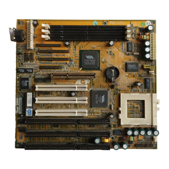
Page 9: Mainboard Layout
System reset switch connector Speaker connector Hard disk activity LED connector Green switch/Green LED connector Turbo LED connector Over-ride power button connector ATX power supply connector SYSFAN System cooling fan connector CPUFAN CPU cooling fan connector 5agm3-1.p65 2000/4/11, PM 05:26... -
Page 10: Chapter 2 Hardware Setup
1. The numbering of the remaining pins follows in sequence. Pins Setting A cap over pin 1 and A 3-pin jumper pin 2 shorts these pins Figure 2-1 5agm3-2.p65 2000/4/11, PM 05:49... -
Page 11: Installing A Pga Type Cpu In A Zif Socket
Figure 2-3 Inserting a CPU into Socket 7 Installing a heat sink and cooling fan on top of your CPU is necessary for proper heat dissipation. Failing to install these items may result in overheating and possible burn-out of your CPU. 5agm3-2.p65 2000/4/11, PM 05:49... -
Page 12: Cpu Jumper Configuration
95/97 x 3.0 x 3.5 x 4.0 x 4.5 x 5.0 x 5.5 Figure 2-4 System Frequency Jumper Settings PCI Frequency & AGP Frequency System Freq. (MHz) PCI Freq. (MHz) AGP Freq. (MHz) 37.5 31.75 63.5 5agm3-2.p65 2000/4/11, PM 05:49... - Page 13 JP4 according to the table on the next page. The voltage range supported by this mainboard is detailed in Figure 2-5 below. Vcore 2.2V 2.3V 2.4V 2.5V 2.8V 2.9V 3.2V 3.3V 3.5V Figure 2-5 Voltage Jumper Settings 5agm3-2.p65 2000/4/11, PM 05:49...
- Page 14 For 97MHz FSB setting, you must first set system frequency to 95MHz (JP5-JP7) and boot the system. Press the Delete key to enter the Award BIOS setup program. Select the Chipset Features option from the Standard CMOS Features menu. At the CPU Clock/PCI Clock function select the 97/32MHz. option. 5agm3-2.p65 2000/4/11, PM 05:49...
-
Page 15: Connector And Jumper Settings
The Soft-power signal, a 5V trickle supply of at least 10mA, is continuously supplied when AC power is available. When the system is in the Soft-Off mode, this trickle supply maintains the system in it's minimum power state. 5agm3-2.p65 2000/4/11, PM 05:49... -
Page 16: Software Power-Off Control
3. Connect the system's power and then start the system. 4. Enter BIOS, load the setup default settings in the CMOS Setup Utility Menu and then set the system configuration in the Standard CMOS Setup menu. 5agm3-2.p65 2000/4/11, PM 05:50... -
Page 17: Over-Ride Power Button
The power indicator LED shows the system's power status and willl flash when the system is in Green mode (Suspend). C. Green Switch/Green LED Connector Definition +5V DC Not Connected Power indicator LED Ground Keylock Keyboard Lock Ground 5agm3-2.p65 2000/4/11, PM 05:50... - Page 18 IDE devices. G. Turbo LED Connector This mainboard does not have turbo/de-turbo speed mode. Even though this function does not exist, the turbo LED will light when the LED is connected and the turbo button is pressed. 5agm3-2.p65 2000/4/11, PM 05:50...
-
Page 19: Poly-Fuse Over Current Protection
If the IR Address Select function in BIOS's Integrated Peripherals menu is not set at disabled, the COM2 port will support IR functions. P in De finition Ir-Tx Ir-Rx Not Connected Vcc (+5V) Not Connected Not Connected Not Connected 5agm3-2.p65 2000/4/11, PM 05:50... - Page 20 This board contains a USB Host controller and includes a root hub with two USB ports (meets USB Rev 1.0 spec.). Two USB peripherals or hub devices are able to be connected. 5agm3-2.p65 2000/4/11, PM 05:50...
-
Page 21: Main Memory Configuration
12ns or faster 4 unbuffered DIMM Modules 384MB 100MHz 10ns or faster Types Supported Synchronous DRAM Speed requirement SDRAM: 10/12ns Module types & sizes 8/16/32/64/128 MBytes, single/double-sided, 3.3v DIMM Parity Both parity and non-parity modules may be used. 5agm3-2.p65 2000/4/11, PM 05:50... - Page 22 ECC and x80 ECC. The unbuffered DIMM is distinguished by the keyed notch lying to the right of the centerline of the DRAM key position as shown in the figure below. 5agm3-2.p65 2000/4/11, PM 05:50...
- Page 23 - Memo 5agm3-2.p65 2000/4/11, PM 05:50...
Need help?
Do you have a question about the 5AGM3 and is the answer not in the manual?
Questions and answers