Table of Contents
Advertisement
Quick Links
Antaira Technologies
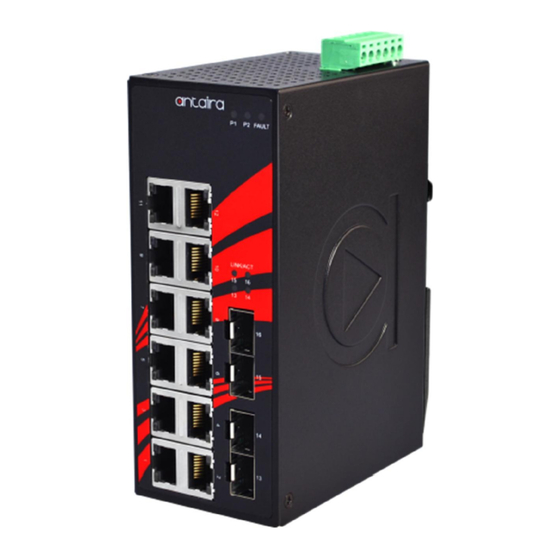
LNX-1604G-SFP series
16-Port Industrial Gigabit Unmanaged Ethernet Switches with
12*10/100/1000Tx + 4*100/1000 SFP Slots
Quick Installation Guide
Version 1.0
Tel: 1-844-268-2472
Fax: 1-714-671-9944
www.antaira.com
Package Check List
The package contains the following items:
Quick Installation Guide
1 * LNX-1604G (-T) Industrial Gigabit Ethernet
Unmanaged Switch
1 * Wall mounting bracket set with screws
1 * DC cable –18 AWG & DC jack 5.5x2.1mm
Front Panel Layout
LAN# 1~12 LED for 1000Mbps
LAN# 1~12 LED for 10/100Mbps
LAN# 1~12 – 10/100/1000 RJ45
Top Panel View
LNX-1604G-SFP series top panel is equipped with one 6-pin
removal terminal block connector for dual DC power inputs
(12-48 VDC).
Product Overview
System Interface/Performance
All RJ-45 ports support the auto MDI/MDI-X function
Ethernet connectivity 12*10/100/1000Tx RJ45 ports
Fiber connectivity with 4*100/1000 Dual rate SFP slots
Store-and-forward switching architecture
8k MAC address table
Jumbo frame support up to 12.2k
Power line EFT protection: 2,000VDC; Ethernet ESD
protection: 6,000VDC
Power Input& Connection
DC 12~48V redundant power, with a 6-pin removal terminal
block
It is recommended to using UL listed Industrial Power
Supply
19020000000002
Operating Temperature
Standard operating temperature model: -10°C ~ 70°C
Extended operating temperature model (–T): -40°C ~ 75°C
Case/Installation
IP-30 protection
DIN-Rail and wall mount design
Safety Precaution
If the DC voltage is supplied by an external circuit, please use a
protection device on the power supply input.
Grounding Screw
LED Indicators
6-Pin Removal Terminal Block (Power Input)
LED
LED for Power 1, Power 2 and Fault
Power 1
Power 2
LAN# 13~16 LED for Network activity
Fault
SFP for LAN# 13~16 100/1000Mbps Fiber
Link Activity
(SFP Port)
LAN Port
1~ 12
(Upper LED)
LAN Port
1~ 12
(Lower LED)
Quick Installation
Ethernet Port
RJ45 Ports (Auto MDI/MDIX)
All RJ-45 ports are auto-sensing for 10Base-T, 100Base-TX or
1000Base-T devices connections. Please follow below wiring pin
assignment table for Ethernet port installation.
Pins
Pin 1
Pin 2
Pin 3
Pin 4
Pin 5
Pin 6
Pin 7
Pin 8
Color
Description
On
Power input 1 is active
Green
Off
Power input 1 is inactive
On
Power input 2 is active
Green
Off
Power input 2 is inactive
On
Power input 1 or 2 is inactive
Red
Off
Both power input 1 and 2 are active
On
Connected to the network with 1000Mbps
Green
Flashing
Networking is active
Off
Not connected to the network
On
Connected to the network with 100Mbps
Amber
Flashing
Networking is active
Off
Not connected to the network
Green
On
Connected to network, 1000Mbps
Flashing
Networking is active
Off
Not connected to network
Green
On
Connected to network, 10/100Mbps
Flashing
Networking is active
Off
Not connected to network
RJ45 Ethernet Port Pin Outs
10/100
1000
T568A Color
T568B Color
Base-T(X)
Base-T
White/Green
White/Orange
Rx+
TP0+
Green
Orange
Rx-
TP0-
White/Orange
White/Green
Tx+
TP1+
Blue
Blue
unused
TP2+
White/Blue
White/Blue
unused
TP2-
Orange
Green
Tx-
TP1-
White/Brown
White/Brown
unused
TP3+
Brown
Brown
unused
TP3-
Advertisement
Table of Contents

Related Manuals for ANTAIRA LNX-1604G-SFP Series


Summary of Contents for ANTAIRA LNX-1604G-SFP Series
- Page 1 Top Panel View 1~ 12 Flashing Networking is active (Upper LED) LNX-1604G-SFP series top panel is equipped with one 6-pin Not connected to network removal terminal block connector for dual DC power inputs Green Connected to network, 10/100Mbps LAN Port (12-48 VDC).
- Page 2 Please follow below steps for connecting the SFP and LC cable: Lightly pull down the bracket on to the rail as shown below in Products supplied by Antaira Technologies are covered in this Insert the SFP transceiver module into the SFP slot as Figure 8.
Need help?
Do you have a question about the LNX-1604G-SFP Series and is the answer not in the manual?
Questions and answers