
Related Manuals for ANTAIRA Lanolinx LNX-1002GN


Summary of Contents for ANTAIRA Lanolinx LNX-1002GN
- Page 1 8-port 10/100TX + 2-port Gigabit Copper/Mini GBIC SNMP Managed Industrial Ethernet Switch with Xtreme Ring User Manual...
- Page 2 Notice The contents in this manual were based on the listed versions shown on the table below (software kernel version, hardware version, and firmware version). If there are any discrepancies between the switch functions and the manual content descriptions, please contact your local distributor for more information.
-
Page 3: Fcc Warning
FCC Warning This Equipment has been tested and found to comply with the limits for a Class-A digital device, pursuant to Part 15 of the FCC rules. These limits are designed to provide reasonable protection against harmful interference in a residential installation. This equipment generates uses and can radiate radio frequency energy and, if not installed and used in accordance with the instructions, may cause harmful interference to radio communications. -
Page 4: Table Of Contents
Content Introduction ..............1 Features ..............1 Package Contents ............ 3 Hardware Description ..........4 Physical Dimension ..........4 Front Panel .............. 4 Bottom View ............. 5 LED Indicators ............5 Ports ................. 7 Cabling ..............8 Wiring the Power Inputs ........... 9 Wiring the Fault Alarm Contact ........ - Page 5 Login in the Console Interface ....... 18 CLI Management ........... 19 Commands Level ............20 Commands Set List............22 Web-Based Management ........45 About Web-based Management ......45 Preparing for Web Management ......45 System Login ............46 Main interface ............47 Main interface ............
- Page 6 Port Statistics ............62 Port Control ............63 Port Trunk .............. 64 Aggregator setting ............64 Aggregator Information ........... 66 State Activity ..............66 Port Mirroring ............67 Rate Limiting ............68 VLAN configuration ..........69 VLAN configuration - Port-based VLAN ......70 802.1Q VLAN ..............
- Page 7 MAC Address Table ............92 Factory Default ............95 Save Configuration ..........95 System Reboot ............96 Troubles shooting ........... 97 Technical Specification ........... 98...
-
Page 8: Introduction
Introduction The 8 10/100TX plus 2 Gigabit Copper/Mini GBIC managed industrial switch is a cost- effective solution and meets the high reliability requirements demanded by industrial applications. The 8 10/100TX plus 2 Gigabit Copper/Mini GBIC managed industrial switch can be easily managed through the Web GUI. By using fiber port can extend the connection distance that increases the network elasticity and performance. - Page 9 TX Packet only RX Packet only Both of TX and RX Packet Security Port Security: MAC address entries/filter IP Security: IP address security management to prevent unauthorized intruder. Login Security: IEEE802.1X/RADIUS IGMP with Query mode for Multi Media Application ...
-
Page 10: Package Contents
Package Contents Please refer to the package content list below to verify them against the checklist. 8 10/100TX plus 2 Gigabit Copper/Mini GBIC managed industrial switch User manual RS-232/RJ-45 cable Block connector 2 wall mount plates and 6 screws ... -
Page 11: Hardware Description
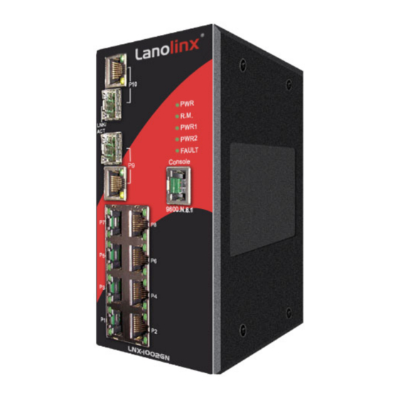
Hardware Description In this paragraph, it will describe the Industrial switch’s hardware spec, port, cabling information, and wiring installation. Physical Dimension 8 10/100TX plus 2 Gigabit Copper/Mini GBIC managed industrial switch dimension (W x D x H) is 72mm x 105mm x 152mm Front Panel The Front Panel of the 8 10/100TX plus 2 Gigabit Copper/Mini GBIC managed industrial switch is showed as below:... -
Page 12: Bottom View
Bottom View The bottom panel of the 8 10/100TX plus 2 Gigabit Copper/Mini GBIC managed industrial switch has one terminal block connector of two DC power inputs. Bottom Panel of the industrial switch LED Indicators There are 7 diagnostic LEDs located on the front panel of the industrial switch. They provide real-time information of system and optional status. - Page 13 Green Power on PWR2 No power inputs Power failure or UTP port failure or Orange Fiber port failure Fault No Power failure or UTP port failure or Fiber port failure occurs The industrial switch is the master Green of Xtreme Ring group R.M.
-
Page 14: Ports
Ports RJ-45 ports There are 8x 10/100Mbps auto-sensing ports for 10Base-T or 100Base-TX devices connection. The UTP ports will auto-sense for 10Base-T or 100Base-TX connections. Auto MDI/MDIX means that the switch can connect to another switch or workstation without changing straight through or crossover cabling. See the below figures for straight through and crossover cable schematic. -
Page 15: Cabling
Straight Through Cable Schematic Cross Over Cable Schematic 2 Mini GBIC/Giga copper combo port: 2 auto-detect Giga port—UTP or fiber. Giga fiber is the mini GBIC module that is optional. Cabling Using four twisted-pair, Category 5 cabling for RJ-45 port connection. The cable between the converter and the link partner (switch, hub, workstation, etc.) must be less than 100 meters (328 ft.) long. -
Page 16: Wiring The Power Inputs
Wiring the Power Inputs Please follow the below steps to insert the power wire. V- V+ V- V+ 1. Insert the positive and negative wires into the V+ and V- contacts on the terminal block connector. 2. To tighten the wire-clamp screws for preventing the DC wires to loose. -
Page 17: Wiring The Fault Alarm Contact
Wiring the Fault Alarm Contact The fault alarm contact is in the middle of terminal block connector as below picture shows. By inserting the wires, it will detect the fault status which the power is failure or port link failure and form a closed circuit. And, application example for the fault alarm contact as below: 1A@24V Insert the wires into the fault alarm contact... -
Page 18: Mounting Installation
Mounting Installation DIN-Rail Mounting The DIN-Rail is screwed on the industrial switch when out of factory. If the DIN-Rail is not screwed on the industrial switch, please see the following pictures to screw the DIN- Rail on the switch. Follow the below steps to hang the industrial switch. Rear Panel of the switch DIN-Rail... - Page 19 First, insert the top of DIN-Rail into the track. Then, lightly push the DIN-Rail into the track. Check if the DIN-Rail is tightened on the track or not. To remove the industrial switch from the track, reverse steps above.
-
Page 20: Wall Mount Plate Mounting
Wall Mount Plate Mounting Follow the below steps to mount the industrial switch with wall mount plate. 1. Remove the DIN-Rail from the industrial switch; loose the screws to remove the DIN- Rail. 2. Place the wall mount plate on the rear panel of the industrial switch. 3. -
Page 21: Hardware Installation
Hardware Installation In this paragraph, we will describe how to install the 8 10/100TX plus 2 Gigabit Copper/Mini GBIC Managed Industrial Switch and the installation points to be attended to it. Installation Steps 1. Unpack the Industrial switch 2. Check if the DIN-Rail is screwed on the Industrial switch or not. If the DIN-Rail is not screwed on the Industrial switch, please refer to DIN-Rail Mounting section for DIN- Rail installation. -
Page 22: Network Application
Network Application This chapter provides some sample applications to help user to have more actual idea of industrial switch function application. A sample application of the industrial switch is as below: Xtreme Ring Application The industrial switch supports the Xtreme Ring protocol that can help the network system to recovery from network connection failure within 20ms or less, and make the network system more reliable. -
Page 23: Coupling Ring Application
Coupling Ring Application In the network, it may have more than one Xtreme Ring group. By using the coupling ring function, it can connect each Xtreme Ring for the redundant backup. It can ensure the transmissions between two ring groups not to fail. The following figure is a sample of coupling ring application. -
Page 24: Dual Homing Application
Dual Homing Application Dual Homing function is to prevent the connection lose from between Xtreme Ring group and upper level/core switch. Assign two ports to be the Dual Homing port that is backup port in the Xtreme Ring group. The Dual Homing function only works when the Xtreme Ring function is active. -
Page 25: Console Management
Console Management Connecting to the Console Port The supplied cable which one end is RS-232 connector and the other end is RJ-45 connector. Attach the end of RS-232 connector to PC or terminal and the end of RJ-45 connector to the console port of switch. The connected terminal or PC must support the terminal emulation program. -
Page 26: Cli Management
After finishing the parameter settings, click “OK“. When the blank screen shows up, press Enter key to bring out the login prompt. Key in the “root“(default value) for the both User name and Password (use Enter key to switch), then press Enter key and the Main Menu of console management appears. -
Page 27: Commands Level
CLI command interface The following table lists the CLI commands and description. Commands Level Access Exit Modes Prompt About This Mode1 Method Method The user commands available at the user level are a subset of Begin a those available at the Enter logout User EXEC session with... - Page 28 while in user Privileged this mode EXEC mode. •Displays advance function status • Save configures Enter the To exit to configure Use this mode to privileged Global command switch configure parameters EXEC Configuration while in (config)# that apply to your mode, enter privileged switch as a whole.
-
Page 29: Commands Set List
Commands Set List System Commands Set Commands Level Description Example show config Show switch switch>show config configuration show terminal Show console switch#show terminal information write memory Save user switch#write memory configuration into permanent memory (flash rom) system name Configure system switch(config)#system name xxx [System Name] name... - Page 30 reload Halt and perform a cold switch(config)#reload restart default Restore to default Switch(config)#default admin username Changes a login switch(config)#admin username [Username] username. xxxxxx (maximum 10 words) admin password Specifies a password switch(config)#admin password [Password] (maximum 10 words) xxxxxx show admin Show administrator switch#show admin information...
- Page 31 server no dhcpserver Disable DHCP server switch(config)#no dhcpserver function security enable Enable IP security switch(config)#security enable function security http Enable IP security of switch(config)#security http HTTP server security telnet Enable IP security of switch(config)#security telnet telnet server security ip Set the IP security list switch(config)#security ip 1 [Index(1..10)] [IP 192.168.1.55 Address]...
- Page 32 operation for Fast Ethernet., the speed can’t be set to 1000 if the port isn’t a giga port.. no flowcontrol Disable flow control of switch(config-if)#no flowcontrol interface security enable Enable security of switch(config)#interface interface fastEthernet 2 switch(config-if)#security enable no security Disable security of switch(config)#interface interface...
- Page 33 Range is from 100 switch(config-if)#bandwidth in 100 kbps to 102400 kbps or to 256000 kbps for giga ports, and zero means no limit. bandwidth out Set interface output switch(config)#interface [Value] bandwidth. Rate fastEthernet 2 Range is from 100 switch(config-if)#bandwidth out kbps to 102400 kbps or to 256000 kbps for giga ports,...
- Page 34 show interface show interface statistic switch(config)#interface accounting counter fastEthernet 2 (config-if)#show interface accounting no accounting Clear interface switch(config)#interface accounting information fastEthernet 2 switch(config-if)#no accounting Trunk Commands Set Commands Level Description Example aggregator priority Set port group system switch(config)#aggregator priority [1~65535] priority aggregator activityport Set activity port...
- Page 35 aggregator group Assign a static trunk switch(config)#aggregator group [GroupID] [Port-list] group. 1 2-4 nolacp nolacp [GroupID] :1~3 [Port-list]:Member port switch(config)#aggregator group list, This parameter 1 3,1,2 nolacp could be a port range(ex.1-4) or a port list separate by a comma(ex.2, 3, 6) show aggregator Show the information switch#show aggregator 1...
- Page 36 grpid switch(vlan)#vlan port-based [GroupID] grpname test grpid 2 port 2,3,4 port [PortNumbers] show vlan [GroupID] Show VLAN switch(vlan)#show vlan 23 information show vlan no vlan group Delete port base switch(vlan)#no vlan group 2 [GroupID] group ID IEEE 802.1Q VLAN vlan 8021q name Change the name of switch(vlan)#vlan 8021q name [GroupName]...
- Page 37 trunk-link tag trunk-link tag 2,3,6,99 [TaggedVID List] switch(vlan)#vlan 8021q trunk 3 trunk-link tag 3-20 vlan 8021q trunk Assign a hybrid link for switch(vlan)#vlan 8021q trunk 3 [PortNumber] VLAN by trunk group hybrid-link untag 4 tag 3,6,8 hybrid-link untag [UntaggedVID] [TaggedVID List] switch(vlan)#vlan 8021q trunk 3 hybrid-link untag 5 tag 6-8 show vlan...
- Page 38 this interval, it recomputed the Spanning Tree Protocol (STP) topology. spanning-tree hello- Use the spanning-tree switch(config)#spanning-tree time [seconds] hello-time global hello-time 3 configuration command to specify the interval between hello bridge protocol data units (BPDUs). spanning-tree forward- Use the spanning-tree switch(config)#spanning-tree time [seconds]...
- Page 39 event of a loop, spanning tree considers the path cost when selecting an interface to place into the forwarding state. stp-path-priority Use the spanning-tree switch(config)#interface [Port Priority] port-priority interface fastEthernet 2 configuration switch(config-if)#stp-path-priority command to configure a port priority that is used when two switches tie for position as the root...
- Page 40 QOS Commands Set Commands Level Description Example qos policy Select QOS policy switch(config)#qos policy [weighted-fair|strict] scheduling weighted-fair qos prioritytype Setting of QOS priority switch(config)#qos prioritytype [port-based|cos- type only|tos-only|cos- first|tos-first] qos priority portbased Configure Port-based switch(config)#qos priority [Port] Priority portbased 1 low [lowest|low|middle|high] qos priority cos Configure COS...
- Page 41 Mac / Filter Table Commands Set Commands Level Description Example mac-address-table static Configure MAC switch(config)#interface hwaddr address table of fastEthernet 2 [MAC] interface (static). switch(config-if)#mac-address- table static hwaddr 000012345678 mac-address-table filter Configure MAC switch(config)#mac-address-table hwaddr address table(filter) filter hwaddr 000012348678 [MAC] show mac-address-table Show all MAC address...
- Page 42 [System Location] system location location lab snmp system-contact Set SNMP agent switch(config)#snmp system- [System Contact] system contact contact where snmp agent-mode Select the agent mode switch(config)#snmp agent-mode [v1v2c|v3|v1v2cv3] of SNMP v1v2cv3 snmp community- Add SNMP community switch(config)#snmp community- strings [Community] string.
- Page 43 match-rule [Exact|Prifix] views [Read View Name] [Write View Name] [Notify View Name] snmpv3 mibview view Configure the mibview switch(config)#snmpv3 mibview [View Name] table of SNMPV3 view V1 type Excluded sub-oid type agent 1.3.6.1 [Excluded|Included] sub-oid [OID] show snmp Show SNMP switch#show snmp configuration no snmp community-...
- Page 44 [Write View Name] [Notify View Name] no snmpv3 mibview Remove specified switch(config)#no snmpv3 view mibview table of mibview view V1 type Excluded [View Name] SNMPV3 agent. sub-oid 1.3.6.1 type [Excluded|Included] sub-oid [OID] Port Mirroring Commands Set Commands Level Description Example monitor rx Set RX destination switch(config)#monitor rx...
- Page 45 8021x enable Use the 802.1x global switch(config)# 8021x enable configuration command to enable 802.1x protocols. 8021x system radiousip Use the 802.1x switch(config)# 8021x system [IP address] system radious IP radiousip 192.168.1.1 global configuration command to change the radious server IP. 8021x system serverport Use the 802.1x switch(config)# 8021x system...
- Page 46 the quiet period value of the switch. 8021x misc txperiod Use the 802.1x misc switch(config)# 8021x misc [sec.] TX period global txperiod 5 configuration command to set the TX period. 8021x misc Use the 802.1x misc switch(config)# 8021x misc supportimeout [sec.] supp timeout global supportimeout 20...
- Page 47 state of the selected port. show 8021x Displays a summary of switch>show 8021x the 802.1x properties and also the port sates. no 8021x Disable 802.1x switch(config)#no 8021x function TFTP Commands Set Commands Level Description Defaults Example backup Save configuration to switch(config)#backup flash:backup_cfg TFTP and need to...
- Page 48 show systemlog Displays system log. Switch>show systemlog show systemlog Show system log switch#show systemlog client & server information no systemlog Disable systemlog switch(config)#no systemlog functon smtp enable Enable SMTP function switch(config)#smtp enable smtp serverip Configure SMTP switch(config)#smtp serverip [IP address] server IP 192.168.1.5 smtp authentication...
- Page 49 both event smtp Set port event for switch(config)#interface [Link-UP|Link- SMTP fastethernet 3 Down|Both] switch(config-if)#event smtp both show event Show event selection switch#show event no event device-cold- Disable cold start switch(config)#no event device- start event type cold-start no event authentication- Disable Authentication switch(config)#no event failure failure event typ...
- Page 50 function is inactive, 20060202-01-01 this command can’t be applied. Parameter format: [yyyymmdd-hh:mm] sntp daylight-offset Set offset of daylight switch(config)#sntp daylight- [Minute] saving time, if SNTP offset 3 function is inactive, this command can’t be applied. sntp ip Set SNTP server IP, if switch(config)#sntp ip 192.169.1.1 [IP] SNTP function is...
- Page 51 Xring master Enable ring master switch(config)#Xring master Xring couplering Enable couple ring switch(config)#Xring couplering Xring dualhoming Enable dual homing switch(config)#Xring dualhoming Xring ringport Configure 1st/2nd switch(config)#Xring ringport 7 8 [1st Ring Port] [2nd Ring Port Ring Port] Xring couplingport Configure Coupling switch(config)#Xring couplingport [Coupling Port] Port...
-
Page 52: Web-Based Management
Web-Based Management This section introduces the configuration and functions of the Web-Based management. About Web-based Management On CPU board of the switch there is an embedded HTML web site residing in flash memory, which offers advanced management features and allow users to manage the switch from anywhere on the network through a standard browser such as Microsoft Internet Explorer. -
Page 53: System Login
System Login Launch the Internet Explorer on the PC Key in “http:// “+” the IP address of the switch”, and then Press “Enter”. The login screen will appear right after Key in the user name and password. The default user name and password are the same as “admin”... -
Page 54: Main Interface
Main interface Main interface... -
Page 55: System Information
System Information Assigning the system name, location and view the system information System Name: Assign the name of switch. The maximum length is 64 bytes System Description: Displays the description of switch. Read only cannot be modified System Location: Assign the switch physical location. -
Page 56: Dhcp Server - System Configuration
inform the user that when the DHCP client is enabling, the current IP will lose and user should find the new IP on the DHCP server. IP Address: Assign the IP address that the network is using. If DHCP client function is enabling, and then user don’t need to assign the IP address. -
Page 57: Dhcp Client - System Configuration
the dynamic IP assigns range. For example: dynamic IP assign range is from 192.168.1.100 ~ 192.168.1.200. 192.168.1.100 will be the Low IP address. High IP Address: the dynamic IP assign range. High IP address is the end of the dynamic IP assigns range. -
Page 58: Dhcp Server - Port And Ip Bindings
DHCP Client Entries interface DHCP Server - Port and IP Bindings You can assign the specific IP address that is the IP in dynamic IP assign range to the specific port. When the device is connecting to the port and asks for dynamic IP assigning, the system will assign the IP address that has been assigned before to the connected device. -
Page 59: Tftp - Restore Configuration
Firmware File Name: the name of firmware image. Click Apply Update Firmware interface TFTP – Restore Configuration You can restore EEPROM value from TFTP server, but you must put the image file on TFTP server first, switch will download back flash image. TFTP Server IP Address: fill in the TFTP server IP. -
Page 60: System Event Log - Syslog Configuration
TFTP Server IP Address: fill in the TFTP server IP Backup File Name: fill the file name Click Apply Backup Configuration interface System Event Log – Syslog Configuration Configuring the system event mode that want to be collected and system log server IP. Syslog Client Mode: select the system log mode –... -
Page 61: System Event Log - Smtp Configuration
Syslog Configuration interface System Event Log - SMTP Configuration You can set up the mail server IP, mail account, account password, and forwarded email account for receiving the event alert. Email Alert: enable or disable the email alert function. SMTP Server IP: set up the mail server IP address (when Email Alert enabled, this function will then be available).. -
Page 62: System Event Log - Event Configuration
in SMTP Server IP Address column. Password: The email account password. Confirm Password: reconfirm the password. Rcpt e-mail Address 1 ~ 6: you can assign up to 6 e-mail accounts also to receive the alert. Click Apply SMTP Configuration interface System Event Log - Event Configuration You can select the system log events and SMTP events. - Page 63 SNMP Authentication Failure, and Xtreme Ring topology change. Mark the checkbox to select the event. When selected events occur, the system will issue the logs. Device cold start: when the device executes cold start action, the system will issue a log event. ...
-
Page 64: Fault Relay Alarm
Event Configuration interface Fault Relay Alarm Power Failure: Mark the check box to enable the function of lighting up FAULT LED on the panel when power fails. Port Link Down/Broken: Mark the check box to enable the function of lighting up FAULT LED on the panel when Ports’... -
Page 65: Sntp Configuration
SNTP Configuration You can configure the SNTP (Simple Network Time Protocol) settings. The SNTP allows you to synchronize switch clocks in the Internet. SNTP Client: enable or disable SNTP function to get the time from the SNTP server. Daylight Saving Time: enable or disable daylight saving time function. When daylight saving time is enabling, you need to configure the daylight saving time period. - Page 66 HAW - Hawaiian -10 hours 2 am Standard Nome, Alaska -11 hours 1 am CET - Central European FWT - French Winter MET - Middle European +1 hour 1 pm MEWT - Middle European Winter SWT - Swedish Winter EET - Eastern +2 hours 2 pm European, USSR Zone 1...
-
Page 67: Ip Security
Standard NZT - New Zealand SNTP Sever URL: set the SNTP server IP address. Daylight Saving Period: set up the Daylight Saving beginning time and Daylight Saving ending time. Both will be different in every year. Daylight Saving Offset (mins): set up the offset time. Switch Timer: Displays the switch current time. -
Page 68: User Authentication
Enable Telnet Server: when checked, the IP addresses among Security IP1 ~ IP10 will be allowed to access via telnet service. Security IP 1 ~ 10: Assign up to 10 specific IP address. Only these 10 IP address can access and manage the switch through the Web browser ... -
Page 69: Port Statistics
Confirm password: Re-type the new password And then, click Apply User Authentication interface Port Statistics The following information provides the current port statistic information. Port: The port number. Type: Displays the current speed of connection to the port. ... -
Page 70: Port Control
Click button to clean all counts. Clear Port Statistics interface Port Control In Port control, you can view every port status that depended on user setting and the negotiation result. Port: select the port that you want to configure. State: Current port status. -
Page 71: Port Trunk
Port Control interface Port Trunk The Link Aggregation Control Protocol (LACP) provides a standardized means for exchanging information between Partner Systems on a link to allow their Link Aggregation Control instances to reach agreement on the identity of the Link Aggregation Group to which the link belongs, move the link to that Link Aggregation Group, and enable its transmission and reception functions in an orderly manner. - Page 72 LACP: If enable, the group is LACP static trunk group. If disable, the group is local static trunk group. All ports support LACP dynamic trunk group. If connecting to the device that also supports LACP, the LACP dynamic trunk group will be created automatically.
-
Page 73: Aggregator Information
Aggregator Information When you have setup the aggregator setting with LACP disabled, you will see the local static trunk group information here. Port Trunk – Aggregator Information interface State Activity When you had setup the LACP aggregator, you can configure port state activity. You can mark or un-mark the port. -
Page 74: Port Mirroring
Port Trunk – State Activity interface Port Mirroring The Port mirroring is a method for monitor traffic in switched networks. Traffic through ports can be monitored by one specific port. That means traffic goes in or out monitored (source) ports will be duplicated into mirror (destination) port. ... -
Page 75: Rate Limiting
Port Trunk – Port Mirroring interface Rate Limiting You can set up every port’s bandwidth rate and frame limitation type. Ingress Limit Frame type: select the frame type that wants to filter. The frame types have 4 options for selecting: All, Broadcast/Multicast/Flooded Unicast, Broadcast/Multicast and Broadcast only. -
Page 76: Vlan Configuration
Rate Limiting interface All the ports support port ingress and egress rate control. For example, assume port 1 is 10Mbps, users can set it’s effective egress rate is 1Mbps, ingress rate is 500Kbps. The switch performs the ingress rate by packet counter to meet the specified rate ... -
Page 77: Vlan Configuration - Port-Based Vlan
receive traffic from the same members of VLAN. Basically, creating a VLAN from a switch is logically equivalent of reconnecting a group of network devices to another Layer 2 switch. However, all the network devices are still plugged into the same switch physically. - Page 78 VLAN – Port Based interface Click to add a new VLAN group(The maximum VLAN group is up to 64 VLAN groups) Entering the VLAN name, group ID and grouping the members of VLAN group And then, click Apply...
- Page 79 VLAN—Port Based Add interface You will see the VLAN displays. button to delete unwanted VLAN. Delete button to modify existing VLAN group. Edit [NOTE] Remember to execute the “Save Configuration” action, otherwise the new configuration will lose when switch power off.
-
Page 80: 802.1Q Vlan
802.1Q VLAN Tagged-based VLAN is an IEEE 802.1Q specification standard. Therefore, it is possible to create a VLAN across devices from different switch venders. IEEE 802.1Q VLAN uses a technique to insert a “tag” into the Ethernet frames. Tag contains a VLAN Identifier (VID) that indicates the VLAN numbers. - Page 81 802.1Q Configuration Enable GVRP Protocol: check the check box to enable GVRP protocol. Select the port that wants to configure. Link Type: there are 3 types of link type. Access Link: single switch only, allow user to group ports by setting the same VID.
- Page 82 Group Configuration interface You can Change the VLAN group name and VLAN ID. Click Apply Group Configuration interface...
-
Page 83: Rapid Spanning Tree
Rapid Spanning Tree The Rapid Spanning Tree Protocol (RSTP) is an evolution of the Spanning Tree Protocol and provides for faster spanning tree convergence after a topology change. The system also supports STP and the system will auto detect the connected device that is running STP or RSTP protocol. -
Page 84: Rstp - Port Configuration
RSTP System Configuration interface RSTP - Port Configuration You can configure path cost and priority of every port. 1. Select the port in Port column. 1. Path Cost: The cost of the path to the other bridge from this transmitting bridge at the specified port. -
Page 85: Snmp Configuration
5. Non Stp: The port includes the STP mathematic calculation. True is not including STP mathematic calculation. False is including the STP mathematic calculation. 6. Click Apply RSTP Port Configuration interface SNMP Configuration Simple Network Management Protocol (SNMP) is the protocol developed to manage nodes (servers, workstations, routers, switches and hubs etc.) on an IP network. -
Page 86: Trap Configuration
String: fill the name of string. RO: Read only. Enables requests accompanied by this string to display MIB-object information. RW: Read write. Enables requests accompanied by this string to display MIB-object information and to set MIB objects. Click To remove the community string, select the community string that you have defined and click . -
Page 87: Snmpv3 Configuration
management stations as trap manager and enter SNMP community strings and selects the SNMP version. 1. IP Address: Enter the IP address of trap manager. 2. Community: Enter the community string. 3. Trap Version: Select the SNMP trap version type – v1 or v2c. 4. - Page 88 User Profile Configure SNMP v3 user table. User ID: set up the user name. Authentication Password: set up the authentication password. Privacy Password: set up the private password. Click to add context name. Click to remove unwanted context name. Remove...
- Page 89 SNMP V3 configuration interface Group Table Configure SNMP v3 group table. Security Name (User ID): Assign the user name that you have set up in user table. Group Name: Set up the group name.
- Page 90 Click to add context name. Click to remove unwanted context name. Remove Access Table Configure SNMP v3 access table. Context Prefix: Set up the context name. Group Name: Set up the group. Security Level: Set up the access level. ...
-
Page 91: Qos Configuration
QoS Configuration You can configure Qos policy and priority setting, per port priority setting, COS and TOS setting. QoS Policy and Priority Type Qos Policy: select the Qos policy rule. Using the 8,4,2,1 weight fair queue scheme: The switch will follow 8:4:2:1 rate to process priority queue from High to lowest queue. -
Page 92: Port Base Priority
QoS Configuration interface Port Base Priority Configure per port priority level. Port 1 ~ Port 10: each port has 4 priority levels – High, Middle, Low, and Lowest. -
Page 93: Cos Configuration
Click Apply COS Configuration Set up the COS priority level. COS priority: Set up the COS priority level 0~7 –High, Middle, Low, Lowest. Click Apply TOS Configuration Set up the TOS priority. TOS priority: the system provides 0~63 TOS priority level. Each level has 4 types of priority –... - Page 94 Message Description A message sent from the querier (IGMP router or switch) Query asking for a response from each host belonging to the multicast group. A message sent by a host to the querier to indicate that the host wants to be or is a member of a given group indicated Report in the report message.
-
Page 95: Xtreme Ring
Xtreme Ring Xtreme Ring provides a faster redundant recovery than Spanning Tree topology. The action is similar to STP or RSTP, but the algorithms not the same. In the Xtreme Ring topology, every switch should enable Xtreme Ring function and assign two member ports in the ring. - Page 96 box to enable the coupling ring function. Coupling port: Assign the member port. Control port: Set the switch as the master switch in the coupling ring. Enable Dual Homing: Set up one of port on the switch to be the Dual Homing port. In an Xtreme Ring group, maximum Dual Homing port is one.
-
Page 97: 802.1X/Radius Configuration
802.1X/Radius Configuration 802.1x is an IEEE authentication specification that allows a client to connect to a wireless access point or wired switch but prevents the client from gaining access to the Internet until it provides authority, like a user name and password that are verified by a separate server. - Page 98 802.1x System Configuration interface 802.1x Per Port Configuration You can configure 802.1x authentication state for each port. The State provides Disable, Accept, Reject and Authorize. Use “Space” key change the state value. Reject: the specified port is required to be held in the unauthorized state. ...
-
Page 99: Mac Address Table
Quiet Period: set the period during which the port doesn’t try to acquire a supplicant. TX Period: set the period the port wait for retransmit next EAPOL PDU during an authentication session. Supplicant Timeout: set the period of time the switch waits for a supplicant response to an EAP request. - Page 100 You can add a static MAC address; it remains in the switch's address table, regardless of whether the device is physically connected to the switch. This saves the switch from having to re-learn a device's MAC address when the disconnected or powered-off device is active on the network again.
- Page 101 MAC Filtering interface MAC Address: Enter the MAC address that you want to filter. Click If you want to delete the MAC address from filtering table, select the MAC address and click Delete All MAC Addresses You can view the port that connected device’s MAC address and related devices’ MAC address.
-
Page 102: Factory Default
All MAC Address interface Factory Default Reset switch to default configuration. Click to reset all configurations to the Reset default value. Factory Default interface Save Configuration Save all configurations that you have made in the system. To ensure the all configuration will be saved. -
Page 103: System Reboot
Save Configuration interface System Reboot Reboot the switch in software reset. Click to reboot the system. Reboot System Reboot interface... -
Page 104: Troubles Shooting
Troubles shooting Verify that is using the right power cord/adapter (DC 24-48V), please don’t use the power adapter with DC output bigger than 48V, or it will burn this converter down. Select the proper UTP cable to construct user network. Please check that is using the right cable. -
Page 105: Technical Specification
Technical Specification The 8 10/100TX plus 2 Gigabit Copper/Mini GBIC managed industrial switch technical specification is following. IEEE 802.3 10Base-T Ethernet IEEE 802.3u 100Base-TX Ethernet IEEE 802.3ab 1000Base-T IEEE 802.3z Gigabit fiber IEEE 802.3x Flow Control and Back-pressure IEEE 802.3ad Port trunk with LACP Standard IEEE 802.1d spanning tree / IEEE802.1w rapid spanning tree... - Page 106 RFC 2665 Ethernet like MIB RFC 2819 RMON MIB Private MIB Up to 3 Trap stations Cold start Port link Up / Port link down Authentication Failure SNMP Trap Private Trap for power status Port Alarm configuration Fault alarm Xtreme Ring topology change Technology Store and forward switching architecture 14,880 pps for 10Base-T Ethernet port...
- Page 107 RJ-45 port: Link/Activity (Green), Full duplex/Collision (Orange) Fiber port: Link/Activity (Green) Per unit: Power (Green), Power 1 (Green), Power 2 (Green), Fault (Orange), Master (Green) 10Base-T: 2-pair UTP/STP Cat. 3, 4, 5 cable EIA/TIA-568 100-ohm (100m) Network Cable 100Base-TX: 2-pair UTP/STP Cat. 5 cable EIA/TIA-568 100-ohm (100m) ...
- Page 108 Port based VLAN IEEE802.1Q Tag VLAN. VLAN Both of port based and Tag based VLAN group up to 256 VLANs. Port Trunk with LACP Port Trunk: 4 Trunk groups/Maximum 4 trunk LACP members IEEE802.1p class of service Class of service Per port provides 4 priority queues.
- Page 109 One relay output for port breakdown and power fail Alarm alarm Alarm Relay current carry ability: 1A @ DC24V Ingress packets filter and egress packet limit. The egress rate control supports all of packet type and the limit rate range is from 100 kbps to 102400 kbps or to 256000 kbps for giga ports, and zero means no limit.
- Page 110 Case Dimension IP-30, 72 mm (W) x 105 mm (D) x 152mm (H) FCC Class A, CE EN61000-4-2 (ESD), CE EN61000-4-3 (RS), CE EN61000-4-4 (EFT), CE EN61000-4-5 (Surge), CE EN61000-4-6 (CS), CE EN61000-4-8, CE EN61000-4-11, CE EN61000-4-12, CE EN61000-6-2, CE EN61000-6-4 Safety CE/EN60950-1 IEC60068-2-32 (Free fall)
Need help?
Do you have a question about the Lanolinx LNX-1002GN and is the answer not in the manual?
Questions and answers