
Related Manuals for ANTAIRA LNX-1802GN


Summary of Contents for ANTAIRA LNX-1802GN
- Page 1 16-port 10/100TX + 2-port 10/100/1000T/Mini GBIC L2 Managed Industrial Ethernet Switch with Redundant Ring User Manual...
- Page 2 FCC Warning This E quipment has been t ested and found to comply with the limits for a Class-A digital device, pur suant t o P art 15 o f the F CC r ules. T hese l imits are designed to provide reasonable protection against harmful interference in a r esidential i nstallation.
-
Page 3: Table Of Contents
Content Introduction ..............I Features ..............I Software Specifications ........... III Package Contents ............ V Hardware Description ..........1 Physical Dimensions ..........1 Front Panel .............. 1 Top View ..............2 LED Indicators ............3 RJ-45 Pin Assignments ..........5 Cabling .............. - Page 4 System Commands Set ..........22 Port Commands Set ............25 Trunk Commands Set ............. 27 VLAN Commands Set ............. 29 Spanning Tree Commands Set ........30 QOS Commands Set ............33 IGMP Commands Set ............. 34 Mac / Filter Table Commands Set ........34 SNMP Commands Set ............
- Page 5 System Event Log – Syslog Configuration ..... 54 System Event Log - SMTP Configuration ....55 System Event Log - Event Configuration ....56 Fault Relay Alarm ..........59 SNTP Configuration ..........59 IP Security .............. 62 User Authentication ..........63 Port Statistics ............
- Page 6 QoS Policy and Priority Type .......... 90 Port-based Priority ............91 COS Configuration ............92 TOS Configuration ............92 IGMP Configuration ..........93 X-Ring ..............94 Security ..............97 802.1X/Radius Configuration .......... 97 MAC Address Table ............100 Factory Default ............. 103 Save Configuration ..........
-
Page 7: Introduction
Introduction The managed industrial switch is a cost-effective solution and meets the high reliability requirements d emanded by i ndustrial ap plications. Using fiber port c an ex tend t he connection distance that increases the network elasticity and performance. Features System Interface/Performance ... - Page 8 Provide redundant backup feature and the recovery time below 20ms Port Trunk with LACP Support IEEE802.1ab LLDP QoS (Quality of Service) Support IEEE 802.1p Class of Service Per port provides 4 priority queues Port Base, Tag Base and Type of Service Priority ...
-
Page 9: Software Specifications
Software Specifications SNMP v1, v2c and v3 management Web interface management Management Telnet interface management Command Line Interface (CLI) management RFC 1215 Trap RFC 1213 MIBII RFC 1157 SNMP MIB RFC 1493 Bridge MIB SNMP MIB RFC 2674 VLAN MIB RFC 1643 RFC 1757 RSTP MIB... - Page 10 Supports 100 entries of MAC address for static MAC and Port Security another 100 for MAC filter TX packet only Port Mirroring RX packet only, Both of TX and RX packets Supports IGMP snooping v1, v2 and v3 IGMP Up to 256 multicast groups and IGMP query Supports 10 IP addresses that have permission to access IP Security the switch management and to prevent unauthorized...
-
Page 11: Package Contents
Supports Primary and Secondary DNS Server Supports SNTP to synchronize system clock with an SNTP Internet time server TFTP firmware update Firmware Update TFTP configuration backup/restoration Configuration Supports binary configuration file for system quick Upload and installation Download Package Contents Please refer to the package content list below to verify them against the checklist. -
Page 12: Hardware Description
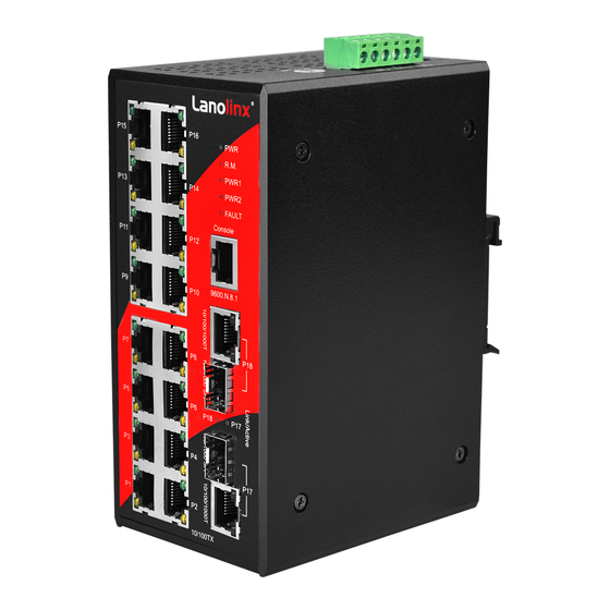
Hardware Description In this par agraph, we will des cribe t he I ndustrial s witch’s har dware s pec, port, c abling information, and wiring installation. Physical Dimensions 16 1 0/100TX + 2 1 0/100/1000T/Mini-GBIC Combo w / X -Ring L2 M anaged Industrial Switch dimensions (W x H x D) are 72mm x 152mm x 105mm Front Panel The front panel of the 16 10/100TX + 2 10/ 100/1000T/Mini-GBIC Combo w/ X-Ring L2... -
Page 13: Top View
Top View The top panel o f t he 16 1 0/100TX + 2 10/100/1000T/Mini-GBIC Combo w / X -Ring L 2 Managed Industrial Switch has one terminal block connector with six contacts. Top Panel of the industrial switch Warning! Airflow around the switch must be unrestricted. -
Page 14: Led Indicators
LED Indicators The diagnostic LEDs located on the front panel of the industrial switch provide real-time information of system and optional status. The following table provides description of the LED status and their meanings for the switch. Status Meaning Green System power on No power inputs The industrial switch is the master device of the... - Page 15 Yellow Ethernet port full duplex (Lower LED) Blinking Collision of packets occurs (Lower LED) Ethernet port half duplex or not connected to (Lower LED) network Green Connected to network (Upper LED) Blinking Networking is active (Upper LED) P17 ~ P18 Not connected to network (10/100/1000T) (Upper LED)
-
Page 16: Rj-45 Pin Assignments
RJ-45 Pin Assignments The UTP/STP ports will automatically sense for Fast Ethernet (10Base-T/100Base-TX) or Gigabit Ethernet (10Base-T/100Base-TX/1000Base-T) connection. Auto MDI/MDIX means that the switch can connect to another switch or workstation without changing straight through or crossover cabling. See the illustrations below for straight through and crossover cable schema. - Page 17 10/100Base-TX Cable Schema Schema Straight Through Cable Crossover Cable Schema 10/100/1000Base-T Pinouts The table below describes the gigabit Ethernet RJ-45 pinouts. Signal name Description BI_DA+ Bi-directional pair A+ BI_DA- Bi-directional pair A- BI_DB+ Bi-directional pair B+ BI_DC+ Bi-directional pair C+ BI_DC- Bi-directional pair C- BI_DB-...
- Page 18 10/100/1000Base-T Cable Schema The following two figures illustrate the 10/100/1000Base-T cable schema. Straight Through Cable Schema Crossover Cable Schema...
-
Page 19: Cabling
Cabling Use four twisted-pair, Category 5e or above cabling for RJ-45 port connection. The cable between the switch and the link partner (switch, hub, workstation, etc.) must be less than 100 meters (328 ft.) long. Gigabit Copper/SFP (mini-GBIC) combo port: ... -
Page 20: Sfp Connection
SFP Connection To connect the transceiver and the LC cable, please follow the steps shown below: First, insert the transceiver into the SFP slot. Notice that the triangle mark indicates the bottom of the slot. Insert transceiver into the SFP slot Transceiver Inserted... - Page 21 Second, insert LC connector of the fiber cable into the transceiver. LC connector to the transceiver...
- Page 22 SFP Disconnection To remove the LC connector from the transceiver, please follow the steps below: First, press down the latches and pull the LC connector out of the transceiver. Press down the latches to remove the LC connector Second, push down the metal loop and pull out the transceiver by the handle. Pull the transceiver out of the slot...
-
Page 23: Wiring The Power Inputs
Wiring the Power Inputs Please follow the steps below to insert the power wire. 1. Insert the positive and negative wires into the V+ and V- contacts on the terminal block connector. 2. Tighten the wire-clamp screws to prevent the DC wires from loosing. -
Page 24: Wiring The Fault Alarm Contacts
Wiring the Fault Alarm Contacts The fault alarm contact is in the middle of terminal block connector as the picture shows below. Inserting the wires, it will detect the fault status which the power is failure or port link failure (for managed model) and form an open circuit. Insert the wires into the fault alarm contacts (No. -
Page 25: Installation
Installation DIN-Rail Mounting Assembling the DIN-Rail Clip The DIN-rail clip is screwed on the industrial switch when out of factory. If not, please refer to the following steps to secure the DIN-rail clip on the switch. 1. Use the included screws to secure the DIN-rail clip on the industrial switch. 2. - Page 26 Hanging the Industrial Switch Follow the steps below to hang the industrial switch on the DIN rail. 1. First, position the rear side of the switch directly in front of the DIN rail. Make sure the top of the clip hooks over the top of the DIN rail. 2.
-
Page 27: Wall Mounting
Wall Mounting To hang the Ethernet switch on the wall, please follow the steps below. 1. Remove the DIN-rail clip. 2. Prepare the two wall-mount plates and six screws included . 3. Align the screw holes bewteen the wall-mount plates and the unit as the figure illustrated . 4. -
Page 28: Installation Steps
Installation Steps 1. Unpack the Industrial switch 2. Check if the DIN-rail clip is screwed on the Industrial switch or not. If the DIN-rail clip is not s crewed on the I ndustrial s witch, pl ease r efer t o t he DIN-Rail Mounting section for DIN-rail installation. -
Page 29: Console Management
Console Management Connecting to the Console Port One e nd of t he s upplied c able i s R S-232 c onnector and t he ot her end i s R J-45 connector. Attach the RS-232 connector to PC or terminal and the RJ-45 connector t o the console port of the switch. -
Page 30: Login In The Console Interface
Login in the Console Interface When the c onnection bet ween S witch and P C i s ready, t urn on t he P C an d r un a terminal em ulation pr ogram or Hyper Terminal and c onfigure i ts communication parameters to match the following default characteristics of the console port: Baud Rate: 9600 bps Data Bits: 8... -
Page 31: Cli Management
Console login interface CLI Management The system supports the console management – CLI command. After you log in on to the system, you will see a command prompt. To enter CLI management interface, type in “enable” command. CLI command interface... -
Page 32: Commands Level
The following table lists the CLI commands and description. Commands Level Access Exit Modes Prompt About This Mode Method Method The user commands available at the user level are a subset of Begin a Enter those available at the logout or User EXEC session with switch>... -
Page 33: Commands Set List
privileged EXEC mode. Enter the To exit to interface of global fast Ethernet configuratio command n mode, Use this mode to enter exit. Interface (with a switch configure parameters configuration specific (config-if)# To exit to for the switch and interface) privileged Ethernet ports. - Page 34 [System Name] name system location switch(config)#system location Set switch system [System Location] location string system description Set switch system switch(config)#system [System Description] description xxx description string system contact switch(config)#system contact Set switch system [System Contact] contact window string show system-info switch>show system-info Show system information...
- Page 35 dhcpserver subnetmask Configure subnet switch(config)#dhcpserver [Subnet mask] subnetmask 255.255.255.0 mask for DHCP clients dhcpserver gateway Configure gateway for switch(config)#dhcpserver [Gateway] gateway 192.168.1.254 DHCP clients dhcpserver dnsip switch(config)#dhcpserver dnsip Configure DNS IP for [DNS IP] 192.168.1.1 DHCP clients dhcpserver leasetime Configure lease time switch(config)#dhcpserver [Hours] leasetime 1...
-
Page 36: Port Commands Set
function no security http switch(config)#no security http Disable IP security of HTTP server no security telnet switch(config)#no security telnet Disable IP security of telnet server Port Commands Set Commands Level Description Example interface fastEthernet Choose the port for switch(config)#interface [Portid] fastEthernet 2 modification. - Page 37 switch(config-if)#no security bandwidth type all Set interface ingress switch(config)#interface fastEthernet 2 limit frame type to switch(config-if)#bandwidth type “accept all frame” bandwidth type Set interface ingress switch(config)#interface broadcast-multicast- fastEthernet 2 limit frame type to flooded-unicast switch(config-if)#bandwidth type “accept broadcast, broadcast-multicast-flooded- multicast, and flooded unicast unicast frame”...
-
Page 38: Trunk Commands Set
limit. show bandwidth Show interfaces switch(config)#interface fastEthernet 2 bandwidth control switch(config-if)#show bandwidth state Use the state interface switch(config)#interface [Enable | Disable] fastEthernet 2 configuration (config-if)#state Disable command to specify the state mode of operation for Ethernet ports. Use the disable form of this command to disable the port. - Page 39 [Group ID] activityport 2 [Port Numbers] aggregator group switch(config)#aggregator group Assign a trunk group [GroupID] [Port-list] 1 1-4 lacp workp 2 with LACP active. lacp [GroupID] :1~3 workp switch(config)#aggregator group [Port-list]:Member port [Workport] 2 1,4,3 lacp workp 3 list, This parameter could be a port range(ex.1-4) or a port list separate by a...
-
Page 40: Vlan Commands Set
no aggregator group Remove a trunk group switch(config)#no aggreator [GroupID] group 2 VLAN Commands Set Commands Level Description Example vlan database switch#vlan database Enter VLAN configure mode Vlanmode switch(vlan)#vlanmode portbase To set switch VLAN [portbase| 802.1q | mode. gvrp] switch(vlan)#vlanmode 802.1q switch(vlan)#vlanmode gvrp no vlan Switch(vlan)#no vlan... -
Page 41: Spanning Tree Commands Set
[UntaggedVID] port belong to a trunk group, this command can’t be applied. vlan 8021q port switch(vlan)#vlan 8021q port 3 Assign a trunk link for [PortNumber] trunk-link tag 2,3,6,99 VLAN by port, if the trunk-link tag [TaggedVID List] port belong to a trunk switch(vlan)#vlan 8021q port 3 group, this command trunk-link tag 3-20... - Page 42 spanning-tree enable Enable spanning tree switch(config)#spanning-tree enable spanning-tree priority Configure spanning switch(config)#spanning-tree [0~61440] priority 32767 tree priority parameter spanning-tree max-age Use the spanning-tree switch(config)#spanning-tree [seconds] max-age 15 max-age global configuration command to change the interval between messages the spanning tree receives from the root switch.
- Page 43 forwarding-time for the specified spanning- tree instances. The forwarding time determines how long each of the listening learning states last before the port begins forwarding. stp-path-cost Use the spanning-tree switch(config)#interface [1~200000000] fastEthernet 2 cost interface switch(config-if)#stp-path-cost 20 configuration command to set the path cost for Spanning Tree Protocol (STP)
-
Page 44: Qos Commands Set
stp-admin-p2p Admin P2P of STP switch(config)#interface [Auto|True|False] fastEthernet 2 priority on this interface. switch(config-if)#stp-admin-p2p Auto stp-admin-edge Admin Edge of STP switch(config)#interface [True|False] fastEthernet 2 priority on this interface. switch(config-if)#stp-admin-edge True stp-admin-non-stp Admin NonSTP of switch(config)#interface [True|False] fastEthernet 2 STP priority on this interface. -
Page 45: Igmp Commands Set
show qos Switch#show qos Displays the information of QoS configuration no qos Disable QoS function switch(config)#no qos IGMP Commands Set Commands Level Description Example igmp enable switch(config)#igmp enable Enable IGMP snooping function Igmp-query auto switch(config)#Igmp-query auto Set IGMP query to auto mode Igmp-query force switch(config)#Igmp-query force... -
Page 46: Snmp Commands Set
[MAC] show mac-address-table switch#show mac-address-table Show all MAC address table show mac-address-table switch#show mac-address-table Show static MAC static static address table show mac-address-table switch#show mac-address-table Show filter MAC filter filter address table. no mac-address-table Remove an entry of switch(config)#interface static hwaddr fastEthernet 2 MAC address table of [MAC]... - Page 47 snmp-server host switch(config)#snmp-server host Configure SNMP [IP address] 192.168.1.50 community public server host community trap-version v1 information and [Community-string] (remove) community string trap-version Switch(config)# [v1|v2c] no snmp-server host 192.168.1.50 snmpv3 context-name switch(config)#snmpv3 context- Configure the context [Context Name ] name Test name snmpv3 user switch(config)#snmpv3 user...
- Page 48 [Excluded|Included] sub-oid [OID] show snmp switch#show snmp Show SNMP configuration no snmp community- switch(config)#no snmp Remove the specified strings [Community] community-strings public community. no snmp-server host switch(config)#no snmp-server Remove the SNMP [Host-address] 192.168.1.50 server host. no snmpv3 user switch(config)#no snmpv3 user Remove specified [User Name] Test...
-
Page 49: Port Mirroring Commands Set
Port Mirroring Commands Set Commands Level Description Example monitor Configure source port switch(config)#interface [RX|TX|Both] fastEthernet 2 of monitor function switch(config-if)#monitor RX monitor rx [Port ID] switch(config)#monitor rx 2 Set RX destination port of monitor function monitor tx [Port ID] switch(config)#monitor tx 3 Set TX destination port of monitor function... - Page 50 8021x system serverport switch(config)# 8021x system Use the 802.1x [port ID] serverport 1815 system server port global configuration command to change the radius server port 8021x system switch(config)# 8021x system Use the 802.1x accountport accountport 1816 system account port [port ID] global configuration command to change the accounting port...
-
Page 51: Tftp Commands Set
configuration command to set the supplicant timeout. 8021x misc switch(config)#8021x misc Use the 802.1x misc servertimeout [sec.] servertimeout 20 server timeout global configuration command to set the server timeout. 8021x misc maxrequest switch(config)# 8021x misc Use the 802.1x misc [number] maxrequest 3 max request global configuration... -
Page 52: Systemlog, Smtp And Event Commands Set
backup Save configuration to switch(config)#backup flash:backup_cfg flash:backup_cfg TFTP and need to specify the IP of TFTP server and the file name of image. restore Get configuration from switch(config)#restore flash:restore_cfg flash:restore_cfg TFTP server and need to specify the IP of TFTP server and the file name of image. - Page 53 smtp account switch(config)#smtp account Configure [account] John authentication account smtp password switch(config)#smtp password Configure [password] 1234 authentication password smtp rcptemail switch(config)#smtp rcptemail 1 Configure Rcpt e-mail [Index] [Email address] Alert@test.com Address show smtp switch#show smtp Show the information of SMTP no smtp switch(config)#no smtp Disable SMTP...
-
Page 54: Sntp Commands Set
event type no event systemlog Disable port event for switch(config)#interface fastethernet 3 system log switch(config-if)#no event systemlog no event smpt Disable port event for switch(config)#interface fastethernet 3 SMTP switch(config-if)#no event smtp show systemlog switch#show systemlog Show system log client & server information SNTP Commands Set Commands... -
Page 55: X-Ring Commands Set
sntp ip switch(config)#sntp ip 192.169.1.1 Set SNTP server IP, if [IP] SNTP function is inactive, this command can’t be applied. sntp timezone switch(config)#sntp timezone 22 Set timezone index, [Timezone] use “show sntp timzezone” command to get more information of index number show sntp switch#show sntp... - Page 56 ring homingport switch(config)#ring homingport 3 Configure Dual [Dual Homing Port] Homing Port show ring switch#show ring Show the information of X - Ring no ring switch(config)#no ring Disable X-ring no ring master switch(config)# no ring master Disable ring master no ring couplering switch(config)# no ring Disable couple ring couplering...
-
Page 57: Web-Based Management
Web-Based Management This section introduces the configuration and functions of the Web-Based management. About Web-based Management There i s an embedded H TML w eb s ite r esiding i n flash m emory on CPU board of t he switch, w hich offers advanced m anagement f eatures an d al lows users t o manage t he switch f rom anywhere on t he n etwork t hrough a s tandard browser s uch as M icrosoft Internet Explorer. -
Page 58: System Login
System Login Launch the Internet Explorer on the PC Key in “http:// “+” the IP address of the switch”, and then Press “Enter”. The login screen will appear right after Key in the user name and password. The default user name and password are the same as ‘root’... -
Page 59: System Information
System Information Assign the system name and location and view the system information System Name: Assign the system name of the switch (The maximum length is 64 bytes) System Description: Describes the switch. System Location: Assign the switch physical location (The maximum length is 64 ... -
Page 60: Dhcp Server - System Configuration
is to inform the user that when the DHCP client is enabled, the current IP will lose and user should find the new IP on the DHCP server. IP Address: Assign the IP address that the network is using. If DHCP client function ... - Page 61 network ad ministration because t he s oftware k eeps t rack o f I P a ddresses rather than requiring an a dministrator to manage the task. This means that a new computer can be added to a network without the hassle of manually assigning it a unique IP address. The system provides the DHCP server function.
-
Page 62: Dhcp Server - Client Entries
DHCP Server – Client Entries When the DHCP server function is active, the system will collect the DHCP client information and displays it at this tab. DHCP Client Entries interface DHCP Server - Port and IP Bindings Assign t he dynamic IP addr ess to t he p ort. When t he device i s c onnecting t o t he por t and asks for IP assigning, the system will assign the IP address that has been assigned before to the connected device. -
Page 63: Tftp - Update Firmware
Port and IP Bindings interface TFTP - Update Firmware It provides the functions that allow user to update the switch firmware. Before updating, make s ure t he TFTP server i s r eady and t he firmware i mage i s located on the T FTP server. -
Page 64: Tftp - Restore Configuration
Update Firmware interface TFTP – Restore Configuration You can restore the configuration from TFTP server. Before doing that, you must put the image file on TFTP server first and the switch will download back the flash image. TFTP Server IP Address: Type in the TFTP server IP. Restore File Name: Type in the correct file name for restoring. -
Page 65: System Event Log - Syslog Configuration
Backup Configuration interface System Event Log – Syslog Configuration Configure the system event mode to collect system log. Syslog Client Mode: Select the s ystem l og mode—Client Only, Server Only, or Both. System Log Server IP Address: Assign the system log server IP. When Syslog Client Mode is set as Client Only, the system event log will only be sent to the client which has logged in on the switch. -
Page 66: System Event Log - Smtp Configuration
Syslog Configuration interface System Event Log - SMTP Configuration You can set up the mail server IP, mail account, password, and forwarded email account for receiving the event alert. Email Alert: Enable or disable the email alert function. SMTP Server IP: Set up the mail server IP address (when Email Alert enabled, this function will then be available). -
Page 67: System Event Log - Event Configuration
will then be available). Mail Account: Set up t he e mail ac count, e. g. johnadmin, t o r eceive t he al ert. I t must b e a n existing em ail ac count o n t he m ail server, w hich you had s et u p i n SMTP Server IP Address column. - Page 68 server/SMTP server. Also, per port log (link up, link down, and both) events can be sent to the system log server/SMTP server with the respective checkbox ticked. After configuring, click to have the setting taken effect. Apply System event selection: There are 4 event types—Device cold start, Device warm ...
- Page 69 Event Configuration interface...
-
Page 70: Fault Relay Alarm
Fault Relay Alarm Power Failure: Tick the checkbox to enable the function of lighting up the FAULT LED on the panel when power fails. Port Link Down/Broken: Tick the checkbox to enable t he function o f l ighting up ... - Page 71 Local Time Zone Conversion from UTC Time at 12:00 UTC November Time Zone - 1 hour 11am Oscar Time Zone -2 hours 10 am ADT - Atlantic Daylight -3 hours 9 am AST - Atlantic Standard -4 hours 8 am EDT - Eastern Daylight EST - Eastern Standard -5 hours...
- Page 72 BT - Baghdad, USSR +3 hours 3 pm Zone 2 ZP4 - USSR Zone 3 +4 hours 4 pm ZP5 - USSR Zone 4 +5 hours 5 pm ZP6 - USSR Zone 5 +6 hours 6 pm WAST - West Australian +7 hours 7 pm Standard...
-
Page 73: Ip Security
SNTP Configuration interface IP Security IP s ecurity f unction a llows the user t o as sign 10 s pecific I P addresses that have permission t o access the s witch t hrough t he w eb browser for the securing switch management. -
Page 74: User Authentication
IP Security interface User Authentication Change web management login user name and password for the management security issue. User name: Type in the new user name (The default is ‘root’) Password: Type in the new password (The default is ‘root’) Confirm password: Re-type the new password And then, click Apply... -
Page 75: Port Statistics
Port Statistics The following information provides the current port statistic information. Port: Displays the port number. Type: Displays the media type of the port. Link: The status of linking—‘Up’ or ‘Down’. State: The user can set the state of the port as ‘Enable’ or ‘Disable’ via Port Control. ... -
Page 76: Port Control
Port Statistics interface Port Control In Port control, you can view and set the operation mode of each port. Port: Select the port that you want to configure. State: Current port status. The port can be set to disable or enable mode. If the port state is set as ‘Disable’, it will not receive or transmit any packet. -
Page 77: Port Trunk
specified period of time. When disabled, the receiving device will drop the packet if too much to process. Security: Once t he Security s election i s s et as ‘On’, any access f rom t he device which connects to this port will be blocked unless the MAC address of the device is included in the static MAC address table. -
Page 78: Aggregator Setting
exchanging i nformation between P artner S ystems o n a l ink t o a llow t heir L ink Aggregation C ontrol instances t o r each agreement o n the i dentity o f t he Link Aggregation G roup t o w hich t he l ink belongs, m ove t he l ink t o t hat Link A ggregation Group, and en able i ts t ransmission a nd r eception functions in an orderly m anner. -
Page 79: Aggregator Information
Click button. Apply button t o del ete Trunk Group. Select t he G roup ID and click Delete Delete button. Port Trunk—Aggregator Setting interface (four ports are added to the left field with LACP enabled) Aggregator Information When you have setup the aggregator setting with LACP disabled, you will see the local static trunk group information in here. -
Page 80: State Activity
Port Trunk—Aggregator Setting interface (two ports are added to the left field with LACP disable) Port Trunk – Aggregator Information interface State Activity Having set up the LACP aggregator on the tab of Aggregator Setting, you can configure the state activity for the members of the LACP trunk group. You can tick or cancel the checkbox beside the state display. -
Page 81: Port Mirroring
Port Trunk – State Activity interface Port Mirroring The Port mirroring is a method for monitoring traffic in switched networks. Traffic through ports can be monitored by one specific port which means traffic goes in or out monitored (source) ports will be duplicated into mirroring (destination) port. - Page 82 Port Trunk – Port Mirroring interface Destination Port: There is onl y one por t c an be selected t o be the destination (mirroring) port f or m onitoring both RX and TX traffic which come f rom the source port.
-
Page 83: Rate Limiting
Rate Limiting You can set up every port’s frame limitation type and bandwidth rate. Rate Limiting interface Ingress Limit Frame type: Select the frame type you want to filter. The frame types have 4 opt ions for s electing: All, Broadcast/Multicast/Flooded Unicast, Broadcast/Multicast, and Broadcast only. - Page 84 1 is 10Mbps; the user can set the effective egress rate of port 1 as 1Mbps, ingress rate 500Kbps. The switch performs the ingress rate by packet counter to meet the specified rate. Ingress: Enter the port effective ingress rate (The default value is “0”). ...
-
Page 85: Vlan Configuration
VLAN configuration A V irtual L AN ( VLAN) is a lo gical net work grouping t hat l imits t he br oadcast d omain, which would allow you to isolate network traffic, so only the members of the same VLAN will receive traffic from the ones of the same VLAN. - Page 86 on no t onl y de fault P VID but al so other i nformation a bout t he packet, s uch as t he protocol. VLAN – Port Based interface Pull down the selection item and focus on Port Based then press button ...
- Page 87 VLAN—Port Based Add interface Enter the group name and VLAN ID. Add the port number having selected into the right field to group these members to be a VLAN group or remove any of them listed in the right field from the VLAN. And then, click button to have the settings taken effect.
- Page 88 VLAN—Port Based Edit/Delete interface button to delete the VLAN. Delete button to modify group name, VLAN ID, or add/remove the members of Edit the existing VLAN group. [NOTE] Remember to execute the “Save C onfiguration” action, ot herwise t he n ew configuration will lose when switch power off.
-
Page 89: 802.1Q Vlan
802.1Q VLAN Tagged-based VLAN is an IEEE 802.1Q specification standard. Therefore, it is possible to create a VLAN across devices from different switch venders. IEEE 802.1Q VLAN uses a t echnique t o i nsert a “ tag” i nto t he E thernet frames. Tag c ontains a V LAN I dentifier (VID) that indicates the VLAN numbers. - Page 90 Access Link: Single switch only, it allows the user to group ports by assigning the same Untagged VID. While this link type is set, the Untagged VID column field is available but the Tagged VID column field is disabled. Trunk Link: The extended application of Access Link.
- Page 91 802.1Q VLAN interface Group Configuration Edit the existing VLAN Group. Select the VLAN group in the table list. Click button. Edit...
- Page 92 Group Configuration interface You can modify the VLAN group name and VLAN ID. Group Configuration interface Click button. Apply...
-
Page 93: Rapid Spanning Tree
Rapid Spanning Tree The Rapid Spanning Tree Protocol (RSTP) is an evolution of the Spanning Tree Protocol and provides for faster spanning tree convergence after a topology change. The system also supports STP and the system will auto-detect the connected device that is running STP or RSTP protocol. -
Page 94: Rstp - Port Configuration
RSTP System Configuration interface RSTP - Port Configuration You can configure path cost and priority of every port. Select the port in the port column field. Path Cost: The cost of the path to the other bridge from this transmitting bridge at ... - Page 95 P2P enabling. False is P2P disabling. Admin Edge: The port directly connected to end stations won’t create bridging loop in the network. To configure the port as an edge port, set the port to “True” status. Admin Non Stp: The por t includes the S TP mathematic calculation. True is n ot ...
-
Page 96: Snmp Configuration
SNMP Configuration Simple N etwork M anagement P rotocol ( SNMP) i s t he protocol developed t o manage nodes (servers, workstations, routers, switches and hubs etc.) on an IP network. SNMP enables network administrators to manage network performance, find and solve network problems, an d pl an for net work g rowth. -
Page 97: Trap Configuration
SNMP System Configuration interface Trap Configuration A trap manager is a management station that receives the trap messages generated by the switch. If no trap manager is defined, no traps will be issued. Create a trap manager by ent ering the I P a ddress of t he s tation an d a c ommunity s tring. To d efine a management station as a trap m anager, assign an I P a ddress, enter the SNMP community strings, and select the SNMP trap version. -
Page 98: Snmpv3 Configuration
Trap Managers interface SNMPV3 Configuration Configure the SNMP V3 function. Context Table Configure SNMP v3 context table. Assign the context name of context table. Click to add context name. Click to remove the unwanted context name. Remove User Profile Configure SNMP v3 user table.. User ID: Set up the user name. - Page 99 SNMP V3 configuration interface Group Table Configure SNMP v3 group table.
- Page 100 Security Name (User ID): Assign the user name that you have set up in user table. Group Name: Set up the group name. Click to add the context name. Click to remove the unwanted context name. Remove Access Table Configure SNMP v3 access table.
-
Page 101: Qos Configuration
QoS Configuration Here you can configure Qos policy and priority setting, per port priority setting, COS and TOS setting. QoS Policy and Priority Type Qos Policy: Select the QoS policy rule. Using the 8,4,2,1 weight fair queue scheme: The s witch w ill f ollow 8: 4:2:1 ... -
Page 102: Port-Based Priority
QoS Configuration interface Port-based Priority Configure the priority level for each port. With the drop-down selection item of Priority Type above being selected as Port-based, this control item will then be available to set... -
Page 103: Cos Configuration
the queuing policy for each port. Port x: Each port has 4 priority levels—High, Middle, Low, and Lowest—to be chosen. Click button to make the settings effective. Apply COS Configuration Set up the COS priority level. With the drop-down selection item of Priority Type above being selected as COS only/COS first, this control item will then be available to set the queuing policy for each port. -
Page 104: Igmp Configuration
IGMP Configuration The Internet Group Management Protocol (IGMP) is an i nternal protocol of the Internet Protocol ( IP) s uite. IP m anages multicast tr affic by us ing s witches, r outers, a nd hosts that s upport I GMP. E nabling I GMP al lows the por ts t o d etect I GMP q ueries, report packets, and manage I P multicast traffic t hrough t he s witch. -
Page 105: X-Ring
IGMP Configuration interface X-Ring X-Ring provides a faster redundant recovery than Spanning Tree topology. The action is similar to STP or RSTP, but the algorithms are different. In t he X -Ring topology, ev ery s witch s hould e nable X -Ring f unction and as sign t wo member ports for connecting to the ring. - Page 106 The system also supports the coupling ring that can connect 2 or more X-Ring group for the r edundant bac kup function and d ual h oming function t hat prevent c onnection l ose between X-Ring group and upper level/core switch. Enable X-Ring: To enable the X-Ring function.
- Page 107 X-ring Interface When the X-Ring function enable, user must disable the RSTP. The X-Ring Note function and RSTP function cannot exist in a switch at the same time. Remember to execute the ‘Save Configuration’ action, ot herwise t he new configuration will lose when switch power off.
-
Page 108: Security
Security In this section, you can configure the 802.1x and MAC address table. 802.1X/Radius Configuration 802.1x is an IEEE authentication specification which prevents the client from connecting to a wireless access point or wired switch until it provides authority, like the user name and password that are verified by an authentication server (such as RADIUS server). - Page 109 802.1x System Configuration interface 802.1x Per Port Configuration You c an c onfigure the 802.1x aut hentication s tate for e ach por t. T he s tate pr ovides Disable, Accept, Reject, and Authorize. Reject: The specified port is required to be held in the unauthorized state. ...
- Page 110 802.1x Per Port Setting interface Misc Configuration Quiet Period: Set the period which the port doesn’t try to acquire a supplicant. TX Period: Set the period the port waits for retransmit next EAPOL PDU during an authentication session. Supplicant Timeout: Set the per iod o f t ime t he s witch w aits for a s upplicant ...
-
Page 111: Mac Address Table
Reauth period: Set the p eriod o f time w hich c lients connected m ust be r e- authenticated. Click button. Apply 802.1x Misc Configuration interface MAC Address Table Use the MAC address table to ensure the port security. Static MAC Address You can add a static MAC address;... - Page 112 Port No.: Pull down the selection menu to select the port number. Click button. If you want to delete the MAC address from filtering table, select the MAC address and click button. Delete Static MAC Addresses interface MAC Filtering By f iltering M AC ad dress, t he s witch c an easily f ilter the pre-configured MAC addr ess and reduce the un-safety.
- Page 113 MAC Filtering interface MAC Address: Enter the MAC address that you want to filter. Click button. If you want to delete the MAC address from the filtering table, select the MAC address and click button. Delete All MAC Addresses You can view the port that connected device’s MAC address and the related devices’ MAC address.
-
Page 114: Factory Default
All MAC Address interface Factory Default Reset s witch t o de fault c onfiguration. Click button to r eset all c onfigurations t o Reset the default value. Factory Default interface Save Configuration Save all configurations that y ou hav e made i n t he s ystem. To ensure t he all... -
Page 115: System Reboot
configuration w ill be saved. Click to s ave t he al l c onfiguration t o t he flash Save memory. Save Configuration interface System Reboot Reboot the switch in software reset. Click to reboot the system. Reboot System Reboot interface... -
Page 116: Troubleshooting
Troubleshooting Verify th at you ar e using t he correct power c ord/adapter. Don’t us e t he power adapter with DC output higher than the power ratings of the equipment. Select t he pr oper U TP/STP c able t o c onstruct the user n etwork. Use uns hielded ... -
Page 117: Technical Specifications
Technical Specifications IEEE 802.3 10Base-T IEEE 802.3u 100Base-TX IEEE 802.3ab 1000Base-T IEEE 802.3z Gigabit fiber IEEE 802.3x Flow Control and Back-pressure IEEE 802.3ad Port trunk with LACP Standard IEEE 802.1d Spanning Tree IEEE 802.1w Rapid Spanning Tree IEEE 802.1p Class of Service IEEE 802.1Q VLAN Tag IEEE 802.1x User Authentication (RADIUS) IEEE 802.1ab LLDP**... - Page 118 EIA/TIA-568 100-ohm (100m) 1000Base-T: 2-pair UTP/STP Cat. 5e or 6 cable EIA/TIA-568 100-ohm (100m) LC (Multi-mode): 50/125um or 62.5/125um Optical Cable LC (Single-mode): 9/125um Back-plane 7.2Gbps Packet Throughput 10.7Mpps at 64bytes Ability 12 ~ 48 V Power Supply Redundant power with polarity reverse protection and removable terminal block Power Consumption...
- Page 119 CE EN61000-4-5 (Surge) CE EN61000-4-6 (CS) CE EN61000-4-8 CE EN61000-6-2 CE EN61000-6-4 UL 60950-1 Safety ISA 12.12.01 UL Class 1 Division 2 IEC60068-2-32 (Free fall) Stability Testing IEC60068-2-27 (Shock) IEC60068-2-6 (Vibration)
Need help?
Do you have a question about the LNX-1802GN and is the answer not in the manual?
Questions and answers