Sign In
Upload
Manuals
Brands
Kval Manuals
Industrial Equipment
Commander III
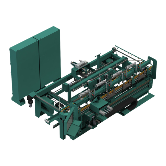
Kval Commander III Manuals
Manuals and User Guides for Kval Commander III. We have
3
Kval Commander III manuals available for free PDF download: Operation Manual, Service Manual
Kval Commander III Operation Manual (168 pages)
Door System With KvalCAM
Brand:
Kval
| Category:
Industrial Equipment
| Size: 5 MB
Table of Contents
Table of Contents
5
Chapter 1 At a Glance
11
Introduction to the Commander III
11
Overview of the Commander III System
12
Table of Options
13
About this Manual
15
Safety Sheet Sign-Off Sheet
15
Safety First
16
Safety Sheet Sign-Off Sheet
16
Safety Terminology of Labels
16
Safety Guidelines
16
Lockout Tagout Procedure
20
Follow the P-R-O-P-E-R Lockout Rule of Thumb
22
Zero-Energy to Start-Up
23
Zero-Energy State to Start-Up to Operating State
23
Getting Help from KVAL
25
On-Line Help
26
Product Return Procedure
26
How to Download the Service Application
27
Download Application
27
Safety Sign-Off Sheet
30
A Note to the Operator
30
Chapter 2 About Kvalcam
33
Summary of the Kvalcam Interface
33
Machine Line
33
Libraries
33
Machine Control
34
About the Libraries
35
Distinguish between the Library Types
35
Around the Door Job Library Screen
36
Around the Door Data Library Screen
36
Around the Feature Group Library Screen
37
Controls at the Library Screen
38
Using the Door File Table
39
Using the Display Deleted Check Box (Recover a Door File)
39
Using the File Control Buttons
40
Using the Create Button
40
Using the Edit/View Button
40
Using the Clone Button
40
Using the Delete/Restore Button
41
Using the Diff Button
42
About the Database Icon
43
About Revisions
44
Principle and Diff
44
Revisions at the Door Job Library
44
Revisions at the Door Data Library
45
Revisions at the Door Feature Group Library
45
About Door Job Creation
47
About the Job Name Menu
48
About the Door Data Menu
48
About the Feature Tree Menu
49
Breakdown of a Feature Group and Features
49
About the Feature Tree Menu
50
About the Selected Feature Details Menu
51
About the Selected Feature Details Menu (Child Level)
52
About the Control Buttons
53
About the Job Preview Screen (2D and 3D)
54
2 D Screen
54
About the Machine Line Screen
56
Machine Line Screen
56
About Backing up Data and Checking the Revision Status
60
Job Preview Examples
61
Door Face (Lock Preview)
61
Door Edge (Lock Preview)
62
Door Edge (Hinge Preview)
63
About Validation
64
About the Validation Screen
65
Outline
66
About the Litecutout Feature Detail (DL-NCD Only)
67
Process
67
About the Litecutout Screen
71
About the Work Area Coordinates
72
Sample Oval Cut
73
Common Terms
75
Door Job
75
Door Data
75
Feature Group
76
Feature
77
Revision
77
Ad Hoc
77
Variant
78
Diff
79
Axis
79
Validation
80
Validation Report
80
Chapter 3 Operation of the Commander III
82
About the Commander III Process
83
Summary of Machining a Door
84
Start the Process
84
Load Door Job from Kvalcam
84
Load Door
85
Set-Up Front Section and Machine the Door
86
Powering Operations for the Commander III
87
How to Power up the Commander III
87
Home the Commander III
88
How to Power down the Commander III
88
Emergency Shutdown and Recovery
89
About Machine Status Feedback
90
About the Commander III Interface Screens
91
Screen Tabs
91
About the Main Control Screen
92
Machine Controls Section
93
About the Main Control Section
94
About Sequence Control Section
95
About Width Adjust
95
About Carriage Control
96
About Ball Catch
97
About Speed Control
97
Machine Feedback and Machine Controls
98
About the Top Feedback Bar
99
About Hinge Tasks Control
99
Hinge Block Descriptives
100
About the Background Colors
100
Shelf Pin Configure and Jamb Stop Section
101
About the Manual Servo Control Screen
103
Manual Servo Control
104
Lock Head Movement
104
Outfeed Stop
104
Hinge Carriage
105
Lock Head Movement
105
About the Tool Config Tabs
106
Unlock the Tool Slot Configuration
107
About Using Tool Configuration
107
Enable or Disable Tool
108
About Hinge Tool Configuration
108
About Lock Tool Configuration
109
About the Ball Catch Configuration
112
About the Tool Path Preview Test Screen
113
About the Status Screen
114
About the Log Screen
115
Calibration of Commander III
116
Chapter 4 At a Glance
116
About Calibration
117
About the Calibration Menus and the Calibration Reference Cut
117
Before You Calibrate
117
Flow Chart of Calibration
118
About the Calibration Tabs
119
Access to the Calibration Adjustments
119
Unlock the Calibration (Option)
120
How to Enter Calibration Data
121
About the Calibration Box
121
About Restore Points
122
Enter a Positive or Negative Number
122
Axis Direction for Front Section
122
Axis Direction for Back Section
123
Suggested Order of Calibration
124
Start with a Right Hand Door
124
Machine a Left Hand Door
124
About the Calibration Screens
125
Summary of Calibrations
125
Opt FC Added Calibrations
126
Summary of Calibrations for Opt FC
126
Hinge Head (over All)
127
Hinge Tools
128
Chisels Calibration
129
Hinge Carriage Location
130
Lock Head
131
Opt FC: Commander III Faceplate and Chisel Calibrations
133
Lock Head General
133
Axis Calibration Direction
134
Plate Router Calibration (Back Section)
134
Chisel Calibration (Back Section)
135
Door Stops
135
Fast and Slow Lock Plate Timing
136
About Lock Plate Timing Calibration
137
Feed System Timing
137
H-Block Display and Jamb Adjustments
138
Door and Jamb Depth Adjustment Mapping
139
Special Options (Calibrations)
141
Thickness Feeler Option
141
Thickness Feeler Calibration
141
Process to Calibrate Thickness Feelers
141
Chapter 5 Tour of the Commander III
143
Operator's Tour
143
Top View
143
In-Feed Section
143
Front Section
146
About the Operators Station
147
Hinge Carriage
148
Back Section
149
Option FC: CNC Faceplate and Chisels
150
Out-Feed
151
About the Electrical Panels
152
The Main Electrical Panel
152
The High Frequency Panel
153
Description of the Six Light Panel
154
About Switches and Sensors
155
Options
157
Option ND: Narrow Door Fence
157
Option W: Lever Lock Drill (Function Drill)
158
Option: Thickness Feelers
159
Option BC: Ball Catch
160
Option SJ: Split Jamb
161
Advertisement
Kval Commander III Operation Manual (124 pages)
Door System With KvalCAM
Brand:
Kval
| Category:
Industrial Equipment
| Size: 5 MB
Table of Contents
Table of Contents
5
Chapter 1 At a Glance
11
Introduction to the Commander III
11
Kvalcam and the Commander III
12
Overview of the Commander III System
12
Standard Features
12
Additional Features
13
Table of Options
14
Bout this Manual
15
Operation Manual
15
Service Manual
15
Kvalcam Reference Manual
16
Safety Sheet Sign-Off Sheet
16
Safety First
17
Safety Guidelines
17
Safety Sheet Sign-Off Sheet
17
Safety Terminology of Labels
17
Follow the P-R-O-P-E-R Lockout Rule of Thumb
21
Lockout-Tagout Guidelines
21
Lockout Tagout Power
22
Lockout Tagout Procedure
22
Pre-Steps before Lockout Tagout
22
Lockout Tagout Air Supply
23
Post Maintenance Steps
23
Start Maintenance
23
Zero-Energy State to Start-Up to Operating State
24
Zero-Energy to Start-Up
24
Getting Help from Kval
26
Acceptance of Return
27
Kval Errors
27
Kval Return and Warranty Policy
27
Refund Turnaround Time
27
Send the Item
27
Customer Errors
28
Shipper Errors
28
Warranty Replacement Parts
28
A Note to the Operator
30
Safety Sign-Off Sheet
30
Operation of the Commander III
31
About the Commander III Process
32
Load Door Job from Kvalcam
33
Start the Process
33
Summary of Machining a Door
33
Load Door
34
Set-Up Front Section and Machine the Door
35
How to Power up the Commander III
36
Powering Operations for the Commander III
36
Home the Commander III
37
How to Power down the Commander III
37
Emergency Shutdown and Recovery
38
About Machine Status Feedback
39
Libraries and Machine Line Screens
40
Screen Tabs
40
Summary of the Kvalcam Interface
40
About the Main Control Screen
41
Machine Controls Section
42
About the Main Control Section
43
About Sequence Control Section
44
About Width Adjust
44
About Carriage Control
45
About Ball Catch
46
About Speed Control
46
Machine Feedback and Machine Controls
47
About Hinge Tasks Control
48
About the Top Feedback Bar
48
About the Background Colors
49
Hinge Block Descriptions
49
Hinge Section Enable or Disable
50
Shelf Pin Configure and Jamb Stop Section
50
Jamb Stop
51
Jamb Stop Spacers
51
About the Manual Servo Control Screen
53
Lock Head Movement
54
Manual Servo Control
54
Hinge Carriage
55
Outfeed Stop
55
Hinge Head Movement
56
About the Tool Config Tabs
57
About Using Tool Configuration
58
Unlock the Tool Slot Configuration
58
Enable or Disable Tool
59
About Hinge Tool Configuration
60
Tool Config Parameter Definitions
60
About Lock Tool Configuration
62
Summary of the Lock Tool Config
62
About the Lock Edge Bore Config
63
About the Lock Edge Plate Config
63
About the Face Bore Config
64
About the Function Drills Config
64
About the Burn Chipout Buttons
65
About the Ball Catch Configuration
66
About the Tool Path Preview Test Screen
67
About the Status Screen
68
About the Log Screen
69
Calibration of Commander III
71
Chapter 3 At a Glance
71
About Calibration
72
About the Calibration Menus and the Calibration Reference Cut
72
Before You Calibrate
72
Flow Chart of Calibration
73
About the Calibration Tabs
74
Access to the Calibration Adjustments
74
Unlock the Calibration (Option)
75
About the Calibration Box
76
How to Enter Calibration Data
76
About Restore Points
77
Axis Direction for Front Section
77
Enter a Positive or Negative Number
77
Axis Direction for Back Section
78
Machine a Left Hand Door
79
Start with a Right Hand Door
79
Suggested Order of Calibration
79
About the Calibration Screens
80
Summary of Calibrations
80
Commander III
81
Opt FC Added Calibrations
81
Summary of Calibrations for Opt FC
81
Hinge Head (over All)
82
Hinge Tools
83
Chisels Calibration
84
Hinge Carriage Location
86
Lock Head
87
Lock Head General
88
Opt FC: Commander III Faceplate and Chisel Calibrations
88
Axis Calibration Direction
89
Plate Router Calibration (Back Section)
89
Chisel Calibration (Back Section)
90
Door Stops
90
Fast and Slow Lock Plate Timing
91
About Lock Plate Timing Calibration
92
Feed System Timing
92
H-Block Display and Jamb Adjustments
93
Door and Jamb Depth Adjustment Mapping
94
Process to Calibrate Thickness Feelers
96
Special Options (Calibrations)
96
Thickness Feeler Calibration
96
Thickness Feeler Option
96
In-Feed Section
99
Operator's Tour
99
Top View
99
Tour of the Commander III
99
Front Section
102
About the Operators Station
103
Hinge Carriage
104
Back Section
105
Option FC: CNC Faceplate and Chisels
106
Out-Feed
107
About the Electrical Panels
108
The Main Electrical Panel
108
The High Frequency Panel
109
About the Nodes
110
Typical Block Diagram of Network Connections
110
Graphical Sample of Node Connections and Power Distribution
111
Description of the Light Tower
112
About Switches and Sensors
113
Option ND: Narrow Door Fence
115
Options
115
Option W: Lever Lock Drill (Function Drill)
116
Option: Thickness Feelers
117
Option BC: Ball Catch
118
Option SJ: Split Jamb
119
Kval Commander III Service Manual (104 pages)
Door System with KvalCam
Brand:
Kval
| Category:
Industrial Equipment
| Size: 12 MB
Table of Contents
Table of Contents
6
Chapter 1 At a Glance
11
Introduction to the Commander III
11
Overview of the Commander III System
12
Table of Options
13
About this Manual
15
Safety Sheet Sign-Off Sheet
15
Safety First
16
Safety Sheet Sign-Off Sheet
16
Safety Terminology of Labels
16
Safety Guidelines
16
Lockout Tagout Procedure
20
Follow the P-R-O-P-E-R Lockout Rule of Thumb
22
Zero-Energy to Start-Up
23
Zero-Energy State to Start-Up to Operating State
23
Getting Help from KVAL
25
On-Line Help
26
Product Return Procedure
26
How to Download the Service Application
27
Download Application
27
Safety Sign-Off Sheet
30
A Note to the Operator
30
System IT Administration
32
Chapter 2 System IT Administration
33
About the Commander III Computer
33
Connections on the PLC
33
About Backing up the Data
34
About Remote Connection to KVAL Service
35
Network Diagram
35
Chapter 3 Maintenance of the Commander III
37
Maintenance Schedule
38
300 Cycle Maintenance Steps
40
Clean, Clean, Clean
40
600 Cycle Maintenance Steps
41
Check Air Gauges and Inspect Water Traps
41
Inspect Tooling
41
Empty Dust Collection Units
42
3,000 Cycle Maintenance Steps
43
Inspect Feed Belts (if Applicable)
43
Inspect All Photo Eyes
43
Inspect Limit Switches
43
Inspect Airlines
44
Refill Lubricators (if Applicable)
44
Grease Ball Screw Bearings
45
Clean Bearing Shafts
45
12,000 Cycle Maintenance Steps
46
Inspect Chains for Proper Tension
46
Inspect Air Cylinders
46
Inspect Hydraulic Lines
46
Inspect Ball Rail Shafts and Ball Screws
47
Clean and Lubricate Slides, Cylinder Rods and Bearing Shafts
47
72,000 Cycle Maintenance Steps
48
Inspect Nuts and Bolts
48
Check Door Feeding Transition
48
Electrical
48
Computer Backup
49
Wash Filter and Lubricator Bowls
49
Maintenance NO-GOES
50
Lubrication Schedule
51
Typical Lucubration Kit
51
Lubrication Requirements
52
Pillow Block Bearing Housings
52
Flange Bearing Housings
53
Ball Rail Bearing
53
About Taper Bearings
54
Tapered Bearing Housings
54
Ball Screw Nut
55
Ball Screw Drive Assembly
55
Pulley and Idler Shafts
56
Sample of Grease Locations for the Machine
57
Front Section Servo Assemblies
60
Grease Locations Cutter Head
61
Cutting Head Base
61
Cutting Head Tools
62
Back Section Grease Points
63
Grease Location on the Frame (Feed System)
64
Air Input with Lubrication
65
Air Line Without Lubricator
66
Replacing Bits in the Front Section
67
Inspect and Clean Collet Assembly
68
How to Access to Bit Assemblies
68
Remove and Replace the Router or Pre-Drill Bits
69
Remove and Replace the Chisels
70
Replacing Tooling in the Back Section
71
Changing the Bore Drill
71
Changing the Bolt Drill
72
Changing the Face Plate Drill
72
Option W: Replacing Function Drill Assembly
73
Collet Torque Values
74
Chapter 4 Troubleshooting the Commander III
77
Get Live Technical Help
77
About Motion Control
78
Basic Control Circuit
79
About a Typical Contactor Control
80
About Contactor Troubleshooting
81
About Typical VFD Motor Drive Control
82
About the VFD
83
About VFD Troubleshooting
84
About a Typical Pneumatic Circuit
85
Typical Pneumatic Assembly
86
About the Coil (Solenoid)
86
About Cylinder Operation
87
How the Pneumatic System Works
87
Important Notice about Adjusting Cylinder Speed
90
Adjusting Cylinder Extend Speed
90
Adjusting Cylinder Retraction Speed
90
About Switches and Sensors
91
Using Sensors to Trouble Shoot
92
Troubleshooting Electrical Problems
93
If the Power Stops During Normal Operation
93
Troubleshooting with the Status Light Panel
95
Control Power Light off
96
Overload Relay Light off
97
E-Stop Light off
97
Stop Light off
97
Start Light off
98
24VDC Light off
98
Network System Overview
99
Connections to Servo Drives
99
Connections to Vfd's (High Freq Panel)
99
Advertisement
Advertisement
Related Products
Kval Commander
Kval 555
Kval 558
Kval 700-C
Kval 700-DC
Kval 960-3
Kval 965X
Kval 990-APEX
Kval 990-F4
Kval 990-HB
Kval Categories
Industrial Equipment
Lifting Systems
Saw
Lathe
Accessories
More Kval Manuals
Login
Sign In
OR
Sign in with Facebook
Sign in with Google
Upload manual
Upload from disk
Upload from URL