
Related Manuals for Kval Commander III


Summary of Contents for Kval Commander III
- Page 1 Operation Manual Published: 12/22/22 Innovation, Quality & Honesty Commander III Door System ® With KvalCAM...
- Page 2 For authorization to copy Kval Inc. this information, please call at (800) 553-5825 or fax (707) 762-0485. Kval Technical Support Manual Name: Commander III Door System Operation Manua Manual Revision: 202-MV100.2, 202-MV101.0, 202-MV101.1 is a trademark of Commander III Kval Incorporated.
- Page 3 KVAL Commander III Operation Manual Technical Support For machinery support and troubleshooting. Call, email, contact us on our website at the “Contact Us” page. Mon-Fri:4:00 AM - 4:00 PM PST email: support@kvalinc.com Field Service Support For any other inquiries or to schedule on-site service. Call, email, contact us on our website at the “Contact Us”...
- Page 4 LICENSE. IF YOU DO NOT AGREE TO ALL OF THE TERMS OF THIS LICENSE, THEN DO NOT USE THE KvalCAM SOFTWARE. KVAL, Inc., is the owner of all rights in respect of the software and documentation (referred to as “Licensor”). You are the purchaser of KVAL Machinery operated by the KvalCAM Software are the “Licensee”.
-
Page 5: Table Of Contents
Table of Contents Introduction to the Commander III Chapter 1 Chapter 1 at a Glance.............. 1-1 Overview of the Commander III System ........1-2 KvalCAM and the Commander III ............1-2 Standard Features ................1-2 Additional Features................1-3 Table of Options...................1-4 bout this Manual ...................1-5 Operation Manual .................1-5... - Page 6 Load Door Job from KvalCAM ..............2-3 Load Door .....................2-4 Set-Up Front Section and Machine the Door........2-5 Powering Operations for the Commander III ......2-6 How to Power Up the Commander III ...........2-6 Home the Commander III ..............2-7 How to Power Down the Commander III ..........2-7 Emergency Shutdown and Recovery ...........2-8...
- Page 7 About the Ball Catch Configuration.......... 2-36 About the Tool Path Preview Test Screen........ 2-37 About the Status Screen............2-38 About the Log Screen .............. 2-39 Calibration of Commander III Chapter 3 Chapter 3 at a Glance.............. 3-1 About Calibration ..............3-2 About the Calibration Menus and the Calibration Reference Cut ..3-2...
- Page 8 Hinge Head (Over All).................3-12 Hinge Tools ..................3-13 Chisels Calibration................3-14 Hinge Carriage Location ..............3-16 Lock Head...................3-17 Opt FC: Commander III Faceplate and Chisel Calibrations....3-18 Lock Head General................3-18 Axis Calibration Direction..............3-19 Plate Router Calibration (Back Section) ..........3-19 Chisel Calibration (Back Section) ............3-20 Door Stops..................3-20...
- Page 9 Table of Contents Option ND: Narrow Door Fence............4-17 Option W: Lever Lock Drill (Function Drill)..........4-18 Option: Thickness Feelers ..............4-19 Option BC: Ball Catch.................4-20 Option SJ: Split Jamb .................4-21 Commander III...
- Page 10 Table of Contents Commander III...
-
Page 11: Introduction To The Commander Iii
Procedure to power up your machine for the first time. page 1-14 Zero-Energy to Start- This section describes the method to contact the Kval page 1-16 Getting Help from service center for help. The section includes how to Kval... -
Page 12: Overview Of The Commander Iii System
Overview of the Commander III System Overview of the Commander III System redefines door and jamb machining flexibility, bridging both residential and Commander III commercial markets. Leveraging our revolutionary software and Beckhoff hardware, KvalCAM® combined with 6-axis movement, the provides on-going return for facilities need- Commander III ing to increase capacity and processing capability. -
Page 13: Additional Features
Overview of the Commander III System torque limiter is now a ball screw so an operator can fasten the first hinge after the hinge head shifts to the second hinge location. A couple of manual adjustments for H blocks and jamb clamps are still necessary, but a pointer and setup mode reduce this to under two minutes and eliminates errors. -
Page 14: Table Of Options
The door files hare identical to those used in the Kval Face, Edge and DLNC series machines so one file can be created to be used in multiple operations. Anti-Static air blow bar to clean door face is also included in this package. -
Page 15: Bout This Manual
Overview of the Commander III System bout this Manual This manual is part of a package delivered with the machine line. Operation Manual includes the following: Operation Manual Chapter Title Description Introduction Descriptions of Machine Line and Safety Information. Operation Inter-... -
Page 16: Kvalcam Reference Manual
Overview of the Commander III System KvalCAM Reference Manual KvalCAM Reference Manual includes the following Chapter Title Description KvalCAM reference Description of the Interface KvalCAM Examples Examples of Common Door Job Features KvalCAM Common Common terms associated with Terms KvalCAM Safety Sheet Sign-Off Sheet At the end of this chapter, there is a safety sign-off sheet. -
Page 17: Safety First
Training Ensure that all employees who operate this machine are aware of and adhere to all safety precautions posted on the machine and are trained to operate this machine in a safe manner. KVAL Commander III Operation Manual... - Page 18 Before performing any mainte- nance or repairs on this machine turn off the main air disconnect. Lockout and tagout this connection. See “Lockout-Tagout Guidelines” on page 1-11. KVAL Commander III Operation Manual...
- Page 19 This should be done in accordance with applicable state and/ or federal code requirements. KVAL Commander III Operation Manual...
- Page 20 Follow Your Company’s Safety Procedures In addition to these safety guidelines. Your company should have on-site and machine specific safety proce- dures to follow. KVAL Commander III Operation Manual 1-10...
-
Page 21: Lockout-Tagout Guidelines
O..OFF! Shut off all power sources and isolating devices P..Place lock and tag E..ENERGY: Release stored energy to a zero-energy state R ..Recheck controls and test to ensure they are in the “OFF” state KVAL Commander III Operation Manual 1-11... -
Page 22: Lockout Tagout Procedure
Lock and Tag out Insert Lock into hole. OFF position Note: When multiple people are working on the machine, each person needs to have a lock on the handle in the extra holes provided. KVAL Commander III Operation Manual 1-12... -
Page 23: Lockout Tagout Air Supply
The lock and tag can now be removed (only by the person(s) who placed them), and the machine can be re-energized. The tags must be destroyed and the locks and keys returned to the lockout center. KVAL Commander III Operation Manual 1-13... -
Page 24: Zero-Energy To Start-Up
Replace Guards Replace all equipment guards. If part of equipment cannot be properly adjusted after start-up with guard on, contact the Service team. See “Getting Help from Kval” Kval on page 1-16. Check Controls Confirm that all switches are in the “OFF”... - Page 25 Be sure to follow the P-R-O- P-E-R lockout/tagout procedures, and that those around you do also. Close the Cage Gate Verify all cage gates are securely closed. Ensure all safety protocols are in effect. KVAL Commander III Operation Manual 1-15...
-
Page 26: Getting Help From Kval
• Outside the U.S. and Canada, call (707) 762-7367 or fax (707) 762-0485 • Email address is service@Kvalinc.com • Hours: 6:00 AM to 4:00 PM Pacific Standard Time, Monday through Thursday 6:30 AM to 1:30 PM Pacific Standard Time, Friday KVAL Commander III Operation Manual 1-16... -
Page 27: Kval Return And Warranty Policy
Kval Return and Warranty Policy Kval Return and Warranty Policy Kval’s goal is to provide customers with high quality products. If, for any reason, you are not completely satisfied with your purchase, please contact us at: Email: parts@kvalinc.com +1 (800) 553-5825 Phone: •... -
Page 28: Customer Errors
Kval provides a warranty to products that are deemed defective. Within 30 days of discovery of said defect, please notify Kval, but no more than one (1) year after delivery will the product be covered under Warranty. The repair, replacement, or payment in the manner described above shall be the exclusive remedy of Buyer for breach of Kval’s warranty or for claims based upon failure... - Page 29 Kval Return and Warranty Policy Page Intentionally Left Blank KVAL Commander III Operation Manual 1-19...
-
Page 30: Safety Sign-Off Sheet
Note: It is recommended you make a copy of this sheet for new operators. If a copy is needed, you may download a PDF at the website ( KVAL http://www.kvalinc.com You may also contact our Service Department at (800) 553-5825 or email at service@kvalinc.com. KVAL Commander III Operation Manual 1-20... -
Page 31: Operation Of The Commander Iii
Chapter 2 at a Glance The following information is available in this chapter. Section Name Summary Page A summary of the Commander III machining pro- page 2-2 About the cess Commander III Process A summary of the steps to machine a door. -
Page 32: About The Commander Iii Process
About the Commander III Process About the Commander III Process Summary of the door process. Download the Door Job. Feed the door into machine. Go to main screen. Make machine adjustments to the displayed values on the main screen if necessary. -
Page 33: Summary Of Machining A Door
Ensure factory air is present at the machine and the main air supply Commander III valve is turned Power up the . See “How to Power Up the Commander III” on page 2- Commander III Select the shortcut to open the program. KvalCAM... -
Page 34: Load Door
Ensure the door is set and clamped in machine. Place the jamb on the Jamb Shelf butted against the stop Press foot pedal to Jamb Clamp clamp the jamb. Jamb Stop Door Clamp Switch Jamb Clamp Switch Jamb Clamps Door Clamps Commander III Operation Manual... -
Page 35: Set-Up Front Section And Machine The Door
If all are finished and the button is active, the door will Groups Door Finished feed out. If needed, move the highlighted the H-Block After all are completed, the door will feed out of the machine. Groups Commander III Operation Manual... -
Page 36: Powering Operations For The Commander Iii
Powering down the system includes: • Shutting down the control power. • Removing power from the entire system. How to Power Up the Commander III Ensure factory air is applied to machine and main air supply is turned on. Check that all buttons are out and safety gate door s are closed. -
Page 37: Home The Commander Iii
The machine will move to the home position at the in-feed end of the machine. The machine will then move to its neutral position. The Commander III is now ready for work. How to Power Down the Commander III Select the button if machine is running. -
Page 38: Emergency Shutdown And Recovery
Powering Operations for the Commander III Emergency Shutdown and Recovery There are emergency shutdown ( ) switches located at key points E-Stop around the machine. Depending on options of the machine, the Note: E-Stop buttons may be located at various locations. -
Page 39: About Machine Status Feedback
This information can be used to troubleshoot any issues that may occur. When activated, the tab will highlight. At the top of the screen, the revi- Note: sion of software is displayed. Commander III Operation Manual... -
Page 40: Summary Of The Kvalcam Interface
Refine and calibrated servo driven assemblies, See Chapter 3. Tool Path Preview See the paths of the tools by way of an animated display. Status information,see “About the Status Screen” on page 2-38. For Information, see “About the Status Screen” on page 2-38. Commander III Operation Manual 2-10... -
Page 41: About The Main Control Screen
The illustration below, shows a screen without a door loaded from the Note: Door Job menu. Machine Controls Machine Feedback and Machine Controls (See page 2-12) (See page 2-17) Commander III Main Screen FIGURE 2-1. Commander III Operation Manual 2-11... -
Page 42: Machine Controls Section
Control the Feed in of the door Carriage Shift Shift the Carriage into pocket and out of pocket. Ball Catch Enable or disable the ball catch function Speed Control Control the percentage of machine speed Commander III Operation Manual 2-12... -
Page 43: About The Main Control Section
Use this mode to check the machine operation without making a cut on the door. With the setup mode set to on, the button will change to an orange back- ground. mode the machine is in normal operation. In the Commander III Operation Manual 2-13... -
Page 44: About Sequence Control Section
• Press and hold the button to close the Close: Close width adjust carriage. To stop the carriage, release the button. The carriage will also stop if the nega- tive travel limit eye is activated. Commander III Operation Manual 2-14... -
Page 45: About Carriage Control
Carriage Shift Button carriage into the machine or away from the machine. Move the carriage out to improve access to the front of the machine and to the tools of the carriage. Commander III Operation Manual 2-15... -
Page 46: About Ball Catch
Ball Catch plied with the machine. About Speed Control Adjust the speed of the cut. Press the graduated speeds or select box or enter a desired speed. The speed can be changed during real time processing. Commander III Operation Manual 2-16... -
Page 47: Machine Feedback And Machine Controls
A display of the sequence of the door machining. Hinge Task Control Information A display of hinge information Shelf Pin and Jamb Stop Jamb Stop (LH) location and Shelf Pin selection. Lock Task Information a display of back section processes Commander III Operation Manual 2-17... -
Page 48: About The Top Feedback Bar
. Adjust each to the settings. See Figure 2- 4 below for the display. See “Hinge Block H-Block type output. Descriptions” on page 2-19 for descriptions of each H-Block Hinge Task Display FIGURE 2- 4. Commander III Operation Manual 2-18... -
Page 49: Hinge Block Descriptions
H-Block not Used: Using not saved or any Door Job has not the Door Job information, been run. this H-Block is not used in the machining procedure. Background Colors FIGURE 2- 6. Commander III Operation Manual 2-19... -
Page 50: Shelf Pin Configure And Jamb Stop Section
Select to toggle the hinge cutting section on or Hinge Enable/ Disable off. When disabled, the background will be gray and the button background will be red. See Figure 2- 10 on page 2-21. Commander III Operation Manual 2-20... -
Page 51: Jamb Stop
Spacers may be custom made to meet facility specifications. To decide which Note: spacer to use, see your facilities mechanical engineer. See Figure 2- 11 below. Jamb Stop Spacer FIGURE 2- 11. Commander III Operation Manual 2-21... - Page 52 • Lock Backset: Feed back only. The length of the backset on the lock. • Edge Plate: Select to enable or disable the edge plate routine. • Edge Bore: Select to enable or disable the edge bore. Lock Task Controls FIGURE 2- 13. Commander III Operation Manual 2-22...
-
Page 53: About The Manual Servo Control Screen
Measurement (Enable/Disable): Auto Feed (Enable /Disable): Press to toggle the operation of Press to toggle the auto feed of the thickness probe (encoder). door ON or OFF. Manual Servo Control Screen FIGURE 2- 14. Commander III Operation Manual 2-23... -
Page 54: Manual Servo Control
Adjust the speed of the Lock Head assem- bly to the desired percentage. Figure 2- 16 shows the on the machine and the controls. Lock Head Lock Head Control FIGURE 2- 16. Commander III Operation Manual 2-24... -
Page 55: Outfeed Stop
Adjust the speed of the assembly to the desired percentage Hinge Carriage Figure 2- 17 below shows the location on the machine and the controls. Hinge Carriage Hinge Carriage Control FIGURE 2- 18. Commander III Operation Manual 2-25... -
Page 56: Hinge Head Movement
Z-Axis: Hinge Head Adjust the speed of the each axis to the desired percentage. Figure 2- 17 below shows the location on the machine and the controls. Hinge Head Lock Head Control FIGURE 2- 19. Commander III Operation Manual 2-26... -
Page 57: About The Tool Config Tabs
• The ability to enable or disable specific tool slots. • The ability to name the tools to familiar names. • The ability to lock and unlock the ability to enter data. List of Tools Available Pop-Up Menus: enter tool data.(Router,Drill and Chisels (opt) Commander III Operation Manual 2-27... -
Page 58: Unlock The Tool Slot Configuration
Identify the tool that needs replacement.Measure the dimensions and capture the data. (Use this information to populate the pop- Drill or Router up screens). Select the Tool Slot. Enter the data into the pop-up screen. Commander III Operation Manual 2-28... -
Page 59: Enable Or Disable Tool
• A red line will cross out the tool on the list. • The tool slot menu will turn red. • The tool will not operate during the cutting process. To Enable • Re-select the Enabled Check-Box. Commander III Operation Manual 2-29... -
Page 60: About Hinge Tool Configuration
An internal reference number for the tool, used in the Gcode file. Counter Rotate When checked, the tool will be used as a counter-rotating tool. Diameter: The nominal diameter for the cutting area of the tool. Commander III Operation Manual 2-30... - Page 61 Max Sized Corner Radius The maximum radius to be chipped away on the corner arc. (inches) Peck Count (pecks/depth An slight touch of the chisel to break the surface of the door material. pass) Commander III Operation Manual 2-31...
-
Page 62: About Lock Tool Configuration
Note: Save Button Tool Config Menu FIGURE 2- 21. Summary of the Lock Tool Config Locations of the Lock Tools are shown in the Figure 2- 22 below. Lock Config Summary FIGURE 2- 22. Commander III Operation Manual 2-32... -
Page 63: About The Lock Edge Bore Config
• Select to toggle between a 3-Degree or 0-Degree cuts. Figure 2- 24 below shows the config input and the type of cut that is affected. Lock Edge Plate Width Depth Length Lock Edge Plate FIGURE 2- 24. Commander III Operation Manual 2-33... -
Page 64: About The Function Drills Config
• Diameter, Depth limit, and Backset location of Lock Bore. Figure 2- 26 below shows the onfig input and the type of cut that is affected. Face Bore c Depth Diameter Backset Face Bore Config FIGURE 2- 26. Commander III Operation Manual 2-34... -
Page 65: About The Burn Chipout Buttons
About the Burn Chipout Buttons At this screen, buttons re available. After the new Chipouts are replaced and secured Burn Chipout in the machine, select these buttons to prepare the for production. Chipouts Burn Chipout Buttons FIGURE 2- 27. Commander III Operation Manual 2-35... -
Page 66: About The Ball Catch Configuration
Note: Ball Catch Ball Catch Location and Config Input screen FIGURE 2- 28. Offset (Top Edge Reference) Depth Backset: Edge of door to the Center of the Hole Ball Catch Parameters FIGURE 2- 29. Commander III Operation Manual 2-36... -
Page 67: About The Tool Path Preview Test Screen
Center Circle represents the tool Point and the animation rep- resents the path Select a G-Code routine form the drop down menu. Select the Render Button View the path of the tool on the screen. Commander III Operation Manual 2-37... -
Page 68: About The Status Screen
The data can be filtered to observe certain aspects of the operation of the machine. This tool is great for troubleshooting to help locate faulty assemblies. Filter Data List of Parameter of Door in Process Status is listed by Location Status Screen FIGURE 2-30. Commander III Operation Manual 2-38... -
Page 69: About The Log Screen
If the machine issue can not be resolved, contact (1-800-553-5825). Have Kval Technical Support any error code that is displayed, ready to give the representative to aid in troubleshooting and Kval shorten downtime. Log Screen FIGURE 2-31. Commander III Operation Manual 2-39... - Page 70 About the Log Screen Commander III Operation Manual 2-40...
-
Page 71: Calibration Of Commander Iii
• Overview of the Setup Screens • Flow Chart of Calibration • Before you Calibrate This section describes the dimensions of the cali- page 3-10 About the Calibration bration slot. Routine KVAL Commander III Operation Manual... -
Page 72: About Calibration
Use Router Bit Depth Gauge (PN: 432C) to check depth. Check for sawdust build-up, which may affect depth. Note: recommends that a test door is run first and checked for specifications Kval before a full run is started. KVAL Commander III Operation Manual... -
Page 73: Flow Chart Of Calibration
About Calibration Flow Chart of Calibration The flow chart below illustrates the steps in performing a calibration on the Commander III Calibration Process Flowchart FIGURE 3- 32. KVAL Commander III Operation Manual... -
Page 74: About The Calibration Tabs
Lists of assemblies to calibrate are in the main body of the page. Calibration Buttons: Unlock a Calibration Calibration Lists: Calibration Input Save a Calibration Select to access calibration adjust- Input Calibration data ments Restore a Calibration Calibration Header FIGURE 3-33. KVAL Commander III Operation Manual... -
Page 75: Unlock The Calibration (Option)
Access to the calibration is password protected (Optional.) Select the button. Unlock At the pop-up, enter Password the password and select OK to continue. The calibration message will change from a red ''Calibration is Locked '' to a green Calibration is Unlocked”. KVAL Commander III Operation Manual... -
Page 76: How To Enter Calibration Data
After every calibration change, select the button to store the calibration. Run a Save test door again to verify the offset correction was successful. Keep running a test door and adjusting the offset until satisfied with the result. KVAL Commander III Operation Manual... -
Page 77: About Restore Points
, then second finger represents Z-Axis Y-Axis the positive the direction of the X-Axis Axis Direction for Front Section In-Feed Y Axis Positive movement Z Axis Positive movement X Axis Positive movement Left Hand Rule Front Section FIGURE 3-34. KVAL Commander III Operation Manual... -
Page 78: Axis Direction For Back Section
Point at the Back Section from the rear of the machine at the cut of the door. In-Feed Y Axis Positive movement Z Axis Positive movement X Axis Positive movement Left Hand Rule Back Section FIGURE 3-35. KVAL Commander III Operation Manual... -
Page 79: Suggested Order Of Calibration
Repeat steps 2 through 3 above until all parameter are in specification. When satisfied with the left hand calibrations, machine a right hand door to verify that all calibrations are set. KVAL Commander III Operation Manual... -
Page 80: About The Calibration Screens
Calibrate the X axis location of the in-feed and out feed stops “Door Stops” on page 3-20 Fast Lock Timing Adjust the time of deployment lock router. see “Fast and Slow Lock Plate Timing” on page 3-21 KVAL Commander III Operation Manual 3-10... -
Page 81: Opt Fc Added Calibrations
Lock Head CNC Tools Calibrate the X, Y, Z axis locations or the diameter of the Lock Plate tool. Calibrate the X,Y, or Z corners of the lock plate chisels “Hinge Head (Over All)” on page 3-12 KVAL Commander III Operation Manual 3-11... -
Page 82: Hinge Head (Over All)
Note: For easy measurement, place a flat 1.0 “spacer between the edge and H-Block the Hinge pocket edge to verify the cut. ‘ Fixed Stop (Right Hand Doors) Movable Stop (Left Hand Doors)- 1.0” 1.0” KVAL Commander III Operation Manual 3-12... -
Page 83: Hinge Tools
Chisel corner off center, overlapping cut pocket, drill holes off center. For example: Note: First verify that the is calibrated before performing any of Hinge Head (Over All) these routines. Select the tool to calibrate inde- pendently of the carriage KVAL Commander III Operation Manual 3-13... -
Page 84: Chisels Calibration
Upper Left Chisel Chisel Jamb Door Lower Left Lower Right Chisel Chisel Adjusting the Chisels Identify the corner or comers to be calibrated. a.Upper Left Chisel b.Upper Right Chisel c.Lower Left Chisel d.Lower Right Chisel. KVAL Commander III Operation Manual 3-14... - Page 85 Click the “ ” button to combine the two numbers to create reference. Combine KVAL Commander III Operation Manual 3-15...
-
Page 86: Hinge Carriage Location
Calibrate the travel across the front section. Normally, calibrate if limits of travel Hinge Carriage of the Head is out of specification. Enter adjustments according to “How to Enter Calibration Data” on page 3-6. KVAL Commander III Operation Manual 3-16... -
Page 87: Lock Head
Once the lock cut is completed, check the distance from the top of the door to the center of the lock. Note the measurement value. (Option: Thickness encoder calibration is also located in this section) KVAL Commander III Operation Manual 3-17... -
Page 88: Opt Fc: Commander Iii Faceplate And Chisel Calibrations
About the Calibration Screens Opt FC: Commander III Faceplate and Chisel Calibrations adds corner squaring and control of face plate routing. machines Option FC Commander III with this option have calibrations. Enter adjustments according to “How to Enter Calibra- added tion Data”... -
Page 89: Axis Calibration Direction
Note the Positive # Negative # measurement value. Run Calibration until specification is met. Z: Positive number Positive moves tools in, negative Number number moves tools out Negative Positive Negative Number Number Number KVAL Commander III Operation Manual 3-19... -
Page 90: Chisel Calibration (Back Section)
These calibrations will set the top of the door references for a right hand and left hand door. See graphic on the next page for calibration axis direction. Enter adjustments according to “How to Enter Calibration Data” on page 3-6. KVAL Commander III Operation Manual 3-20... -
Page 91: Fast And Slow Lock Plate Timing
The router time can be adjusted to match the flow control that is mounted on Slow Plate Routine the valve for slow sequence. Before adjusting the time, make sure the Fast Plate Routine is set properly before adjusting times and flow controls in this section. KVAL Commander III Operation Manual 3-21... -
Page 92: About Lock Plate Timing Calibration
This number is in seconds. If there is a delay before the vertical moves, enter a smaller number in this box. Feed System Timing Calibrates the In-feed and Out-feed timing of the door into the machine. Adjust until the Stop tim- ing with the door is in synchronization. KVAL Commander III Operation Manual 3-22... -
Page 93: H-Block Display And Jamb Adjustments
About the Calibration Screens H-Block Display and Jamb Adjustments No servo adjustments are performed in these calibrations. This calibration is used ensure the front tape matches the display output. KVAL Commander III Operation Manual 3-23... -
Page 94: Door And Jamb Depth Adjustment Mapping
If it is too shallow, enter a positive number to adjust the routers. Machine another door and repeat until offset is corrected. KVAL Commander III Operation Manual 3-24... - Page 95 0.0100 into the jamb portion of the menu at the 45- 60 range: Jamb was set at 0.0100, combined 0.0100 to set at 0.0200 ” Door and Jamb Adjustment FIGURE 3- 32. Fast Lock Plate Timing Menu FIGURE 3- 33. KVAL Commander III Operation Manual 3-25...
-
Page 96: Special Options (Calibrations)
Measure a know good door. The door should be true and possible. Capture the . (This measurement is used to compare to the thickness Thickness Measurement captured by the feeler encoders.) the door into the machine. 2. Auto Feed KVAL Commander III Operation Manual 3-26... - Page 97 Enter the offsets from the averages and the measured door in the boxes under the Menus. Door Width Feelers Door Length Feelers Enter a negative offset to move the thickness adjust clamps closer. Enter a positive offset to move the thickness adjust clamps further apart. KVAL Commander III Operation Manual 3-27...
- Page 98 Special Options (Calibrations) KVAL Commander III Operation Manual 3-28...
-
Page 99: Tour Of The Commander Iii
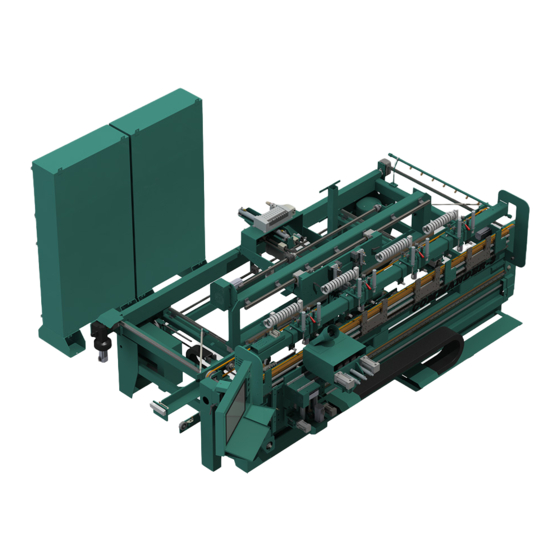
Tour of the Commander III CHAPTER 4 This chapter describes components, assemblies of the Commander III Chapter 4 at a Glance The following information is available in this chapter Section Name Summary Page Descriptions of the operation of the parts and page 4-2 Operator’s Tour... - Page 100 Back Section See “Back Section:” on page 4-7. Ball Catch (X2) See “Option BC: Ball Catch” on page 4-20. Out Feed “Out-Feed:” on page 4-9. Identification of Key Assemblies of Commander III FIGURE 4- 36. KVAL Commander III Operation Manual...
- Page 101 Adjusts to the width of the door Feed Motor: Drives the Door In-Feed System: Door Enters Machine through the here. Sensors triggered and width is machine. adjusted to door Key Assemblies on the In-Feed Section FIGURE 4- 37. KVAL Commander III Operation Manual...
-
Page 102: Front Section
• Operator Station • Hinge Carriage • H Blocks • Door Stops • Jamb Stop • jamb Clamps Door Stops: Located at In-Feed and Out-Feed Operator Station Jamb Stop Hinge Carriage H Block Jamb Clamps KVAL Commander III Operation Manual... -
Page 103: About The Operators Station
Start or Stop Control Transformer Start Sequence Machine (Com- (Start cutting) (System ON or OFF) puter ON or OFF) E Stop(: Press to Stop all machine functions Operators Station with touch Screen Interface FIGURE 4- 38. KVAL Commander III Operation Manual... -
Page 104: Hinge Carriage
Standard Router. Provides a cleaner cut. Chisels: Squares the hinge pocket. Upper chisels process the pocket on the jamb. Lower chisels process the pocket on the door Hinge Carriage Parts FIGURE 4- 40. KVAL Commander III Operation Manual... -
Page 105: Back Section
Lock Bore Motor and Drill: Face Plate Motor and Drill: Drills locks holes on the face Feed Belt: Routs face plate. of the door Feeds Door through Machine Key Assemblies on the Back Section FIGURE 4- 41. KVAL Commander III Operation Manual... -
Page 106: Option Fc: Cnc Faceplate And Chisels
Bolt Drill Motor: Machines lock plate on the side of the door. Left Lock Plate Right Lock Plate Chisel Cylinder: Chisel Cylinder: Squares the edge Squares the edge of the lock plate. of the lock plate. KVAL Commander III Operation Manual... -
Page 107: Out-Feed
Option: Door hand indicator light to speed processing in a companion 700C door framer. Red Light indicates Right hand door is being out Fed. A reset for the 700 C is also available. Key Assemblies on the Out-Feed Section FIGURE 4- 42. KVAL Commander III Operation Manual... -
Page 108: About The Electrical Panels
Servo Drives • X-Axis • Y Axis • Z-Axis Control • Hinge Carriage Transformer • Out-Feed Stop • Lock Location • Feed Overview of Main Electrical Panel and High Frequency Panel FIGURE 4- 43. KVAL Commander III Operation Manual 4-10... -
Page 109: The High Frequency Panel
High Voltage Section (Input, Fuses. PDR,) Breakers VFD Section • Counter Rotate Hinge Router • Hinge Router • Pre Drill Router • Face Plate Router • Width Adjust Overview of High Frequency Panel FIGURE 4- 44. KVAL Commander III Operation Manual 4-11... -
Page 110: About The Nodes
Top Ethernet cable is PLC Bottom Ethernet goes to Cutter Node Interconnect Bar Sample of a Frame Node FIGURE 4- 45. Typical Block Diagram of Network Connections Block Diagram of Network Connections FIGURE 4- 46. KVAL Commander III Operation Manual 4-12... -
Page 111: Graphical Sample Of Node Connections And Power Distribution
Graphical Sample of Node Connections and Power Distribution Power Power Dis- tributed to Points in the machine Main E Box: Contains Servo Drives Network Connec- tions, power, and Inputs/Outputs originate this box and are connected Frame Nodes to Nodes. KVAL Commander III Operation Manual 4-13... -
Page 112: Description Of The Light Tower
• Flashing: Not Ready to Re-Start (E-Sop Switch is Active) Green: Machine is Operational Off: No Control Power Control Power ON (Green): 24 VDC Control Power ON Ready to Work Light Tower Rev 2 KVAL Commander III Operation Manual 4-14... -
Page 113: About Switches And Sensors
24VDC and sends it to the • As a result, if a metal object is sensed, the output of the sensor equals 0VDC Sensors on Piston and Cylinder KVAL Commander III Operation Manual 4-15... - Page 114 • .Depending on the model of limit switch, the amount of “pre-travel” (amount of movement from the arms resting position) is either 5 or 20 degrees before the limit switch actuates (Clicks). Switch Arm KVAL Commander III Operation Manual 4-16...
-
Page 115: Options
Note: The Lock functions is not available with this option. Standard Door Narrow Door Sensors: The Sensors width of the door is com- pared to the Standard Sen- sor inputs to activate. Narrow Door Fence Pneumatic Con- trols for Narrow Door KVAL Commander III Operation Manual 4-17... -
Page 116: Option W: Lever Lock Drill (Function Drill)
Drill Patterns are stored in the software and can be selected from a drop down list. For information on the drop-down list, see Chapter 2 of this manual. To see information about changing a drill assembly, see then Maintenance chapter of the Service Manual. Lever Lock (Function Drill) KVAL Commander III Operation Manual 4-18... -
Page 117: Option: Thickness Feelers
Thickness Feeler on the back section of the machine. Thickness Feeler Menu Additions Some added features to the interface for this option are located in the Calibration Screen and the Manual Screen. KVAL Commander III Operation Manual 4-19... -
Page 118: Option Bc: Ball Catch
Ball Catch Ball Catch Motor and Drill: Drills ball catch top edge (In-Feed) on RH Door Ball Catch Motor and Drill: Drills ball catch top edge (Out-Feed) on LH Door. KVAL Commander III Operation Manual 4-20... -
Page 119: Option Sj: Split Jamb
Load jamb assembly into machine. During process, press the Fire Side Nailer Button. Nailer Button: Push to The Stapler Assembly will move into place staple the split jamb and fire the staples. KVAL Commander III Operation Manual 4-21... - Page 120 Options KVAL Commander III Operation Manual 4-22...
- Page 121 3-24 overview electrical panels description 4-10 location in main electrical panel 4-10 emergency shutdown power description lock out procedure 1-12 powering up and down machine fast lock plate timing pre-drill calibration 3-21 calibration 3-20 KVAL Commander III Operation Manual...
- Page 122 4-15 voltage levels 4-15 six light panel description 4-14 slow lock plate timing calibration 3-23 start machine button power up Start Sequence 2-13 tagout procedure 1-12 zero-energy start-up clean up 1-14 inspect 1-14 KVAL Commander III Operation Manual...
- Page 124 Customer Service Contacting KVAL Phone and Fax: Mailing address: In the U.S and Canada, call (800) 553-5825 or fax Customer Support Department (707) 762-0485 Kval Incorporated Outside the U.S. and Canada, call (707) 762-7367 825 Petaluma Boulevard South or fax (707) 762-0485 Petaluma, CA 94952 Email: service@kvalinc.com...
Need help?
Do you have a question about the Commander III and is the answer not in the manual?
Questions and answers