Table of Contents
Advertisement
Quick Links
UM2520
User manual
How to use the 3 kW three-channel interleaved PFC based on the STNRGPF01
digital controller
Introduction
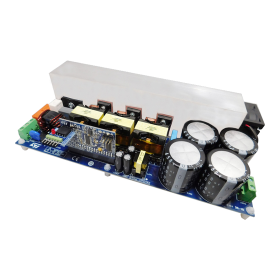
The STEVAL-IPFC01V1 3 kW interleaved PFC reference design is based on the STNRGPF01 digital controller and includes a
separate power board, control board and programming board. The STNRGPF01 is a digital configurable ASIC developed by
STMicroelectronics, which can drive up to three channels in an interleaved PFC for industrial applications.
The
STNRGPF01
digital controller on the control board implements mixed signal (analog/digital) average current mode control
in CCM at fixed frequency. The analog section ensures cycle-by-cycle current regulation, while digital control manages the non-
time critical operations. You can use the
eDesignSuite
software available on the ST website to configure the
STNRGPF01
to
satisfy the specifications of each interleaved PFC.
Figure 1.
STEVAL-IPFC01V1 3 kW interleaved PFC reference design
UM2520 - Rev 3 - October 2019
www.st.com
For further information contact your local STMicroelectronics sales office.
Advertisement
Table of Contents

Related Manuals for ST UM2520


Summary of Contents for ST UM2520
-
Page 1: Figure 1. Steval-Ipfc01V1 3 Kw Interleaved Pfc Reference Design
CCM at fixed frequency. The analog section ensures cycle-by-cycle current regulation, while digital control manages the non- time critical operations. You can use the eDesignSuite software available on the ST website to configure the STNRGPF01 satisfy the specifications of each interleaved PFC. -
Page 2: Safety Instructions
The same personnel must be aware of and must apply national accident prevention rules. The electrical installation shall be completed in accordance with the appropriate requirements (e.g., cross- sectional areas of conductors, fusing, and GND connections). UM2520 - Rev 3 page 2/28... -
Page 3: Steval-Ipfc01V1 Evaluation Kit Overview
Cycle-by-cycle regulation (analog current control loop) • Input voltage and load feed-forwards • Phase shedding • Burst-mode operation • Overvoltage protection • Thermal protection • Status indicator LEDs • Inrush current limiter function • Cooling function UM2520 - Rev 3 page 3/28... -
Page 4: How To Use The Steval-Ipfc01V1 Evaluation Board
STEVAL-IPFC01C1 insertion in STEVAL-IPFC01P1 J301 connector J301 Step 2. Connect a 230 V/50 Hz or 115 V/60 Hz AC source to the J2 connector on the STEVAL-IPFC01P1 power board. Figure 4. STEVAL-IPFC01V1 AC source connection AC IN UM2520 - Rev 3 page 4/28... -
Page 5: Steval-Ipfc01P1 Power Board Startup Sequence
Once the auxiliary voltages are nominal, the inrush current limiter phase begins by charging the output capacitor until the DC voltage reaches the peak input voltage. The charge current is limited by resistor R101. UM2520 - Rev 3 page 5/28... -
Page 6: Figure 6. Steval-Ipfc01V1 Dc Input Connection
If the load is connected before the Inrush current limiter phase, a very high current will flow into the PFC and possibly damage the board when the relay closes the contacts across resistor R101. UM2520 - Rev 3 page 6/28... -
Page 7: Pfc Controller Customization With Edesign Suite
PFC controller customization with eDesign Suite eDesignSuite suite software tool developed by STMicroelectronics helps you configure ST products power conversion applications. You can use it to customize the PFC controller for a specific application: you start by entering the main specifications for your design and then generate an automatic design or follow a sequential process to build a highly customized design. -
Page 8: Figure 8. Pfc Step-By-Step Design
UM2520 PFC controller customization with eDesign Suite Figure 8. PFC step-by-step design RELATED LINKS See RM0446 for details on how to use eDesignSuite to generate specialized firmware UM2520 - Rev 3 page 8/28... -
Page 9: Status Leds And Fault Conditions
Input voltage dropout when the input voltage signal disappears for more than 25 ms. Under these conditions, the STNRGPF01 will drive both LEDs on the control board off and will wait until the conditions have cleared before repeating the startup sequence. UM2520 - Rev 3 page 9/28... -
Page 10: Steval-Ipfc01P1 Power Board Schematics
STEVAL-IPFC01P1 power board schematics Figure 9. STEVAL-IPFC01P1 schematic - input section D100 RL100 STPS1L30A R100 22 Q100 RELAY STS6NF20V 250Vac-16A F100 AC-IN-L1 R102 AC-IN-L2 R101 J100 R103 470k N.M. Y100 RV100 L100 2.2nF V_INPUT R104 C100 470k S14K275 N.M. D101 2x 4.5 mH Y101 2.2nF... -
Page 11: Figure 10. Steval-Ipfc01P1 Schematic - Auxiliary Power Supply
Figure 10. STEVAL-IPFC01P1 schematic - auxiliary power supply +400V D200 SM6T220A D201 STPS2150A L2004.7µH L201 D202 C200 C201 C202 R200 STTH1L06A 3.3k 470nF 470µF 470µF R202 D203 STPS1L30A U200 VOUT GND4 GND1 2.2mH GND3 GND2 INHIBIT D204 TMMBAT46 C203 C204 R203 470nF L4931ABD50-TR... -
Page 12: Figure 11. Steval-Ipfc01P1 Schematic - Boost Interleaving Section
Figure 11. STEVAL-IPFC01P1 schematic - boost interleaving section L300INDUCTOR +400V V_INPUT L301INDUCTOR VOUT D300 STPSC12065 L302INDUCTOR C304 C300 C301 C302 C303 D301 STPSC12065 0.56uF 470uF 470uF 470uF 470uF D302 J300 STPSC12065 R300 R301 470k R302 R303 C305 C306 R306 R307 10nF R305 R304... -
Page 13: Steval-Ipfc01C1 Control Board Schematic
STEVAL-IPFC01C1 control board schematic Figure 12. STEVAL-IPFC01C1 schematic VDDA PWM0 PWM0 WE-CBF PWM1 PWM0 4.7µF 100nF 10nF 10nF 100nF RED LED I_in2 GREEN LED 47µF PIN29 RELAY RELAY TEMP TEMP GREEN VBUS VBUS I_LOAD I_LOAD 1µF CCO_clk VCOUT CLOCK OCP1 OCP1 PWM0 100pF... -
Page 14: Steval-Ipfc01A1 Adapter Board Schematic
STEVAL-IPFC01A1 adapter board schematic Figure 13. STEVAL-IPFC01A1 schematic CON6 CON4 J400 D400 R403 Q400 MMBT2222ALT1G R401 330 R402 470k... -
Page 15: Steval-Ipfc01V1 3 Kw Interleaved Pfc Bill Of Materials
±20% through hole lead spacing 10mm POLYPROPILENE 0.56µF, 450V, FILM CAP, through C304 EPCOS B32673P6564K000 ±10% hole lead spacing 22.5mm POLYPROPILENE 1µF, 520V, FILM CAP, through C305 EPCOS B32673Z5105K000 ±10% hole lead spacing 22.5mm UM2520 - Rev 3 page 15/28... - Page 16 600V, 12A voltage rectifier, STPSC12065D D302 TO220AC Small signal D315 100V, 150mA Schottky diode, BAT46JFILM SOD-323 Cylindrical Fuse 20A, 250Vac, F100 Class gG/gL and Bel Fuse Inc. SMM 20 20A, 0% aM, SMD 10x3 mm UM2520 - Rev 3 page 16/28...
- Page 17 R362 0603 R103, R104, R112, R113, 470k, 200V, Metal film resistor, R301, R304, ±1% 1206 R308 R105, R108, Metal film resistor, 33k, 200V, ±1% R109 1206 100k, 200V, Metal film resistor, R106 ±1% 1206 UM2520 - Rev 3 page 17/28...
- Page 18 Film Resistor, 1206 Wirewound Res., R319, R321, 10m, ±1% Precision, SMD OHMITE MCS3264R010FER R323 2512 3.3k ±0.1%, Metal film resistor, R324 75V, 0% 0603 Metal film resistor, R326 4m, ±1% Vishay WSLP39214L000FEA SMD 3921 UM2520 - Rev 3 page 18/28...
- Page 19 V precision analog U306 STLM20W87F temperature sensor, SOT323-5L 4 A dual low side U307, U308, 18V, 4A MOSFET driver, PM8834TR U309 Ceramic disc cap, T 2.2nF, 250V, Y100, Y101 H lead spac. 7.5 MURATA DE2E3KH222MA3B ±20% UM2520 - Rev 3 page 19/28...
-
Page 20: Steval-Ipfc01C1 Control Board Bill Of Materials
V, 5 % Capacitor 100nF, 0603, 50 X7R Ceramic V, 10 % Capacitor 15nF, 0603, 50 X7R Ceramic V, 10 % Capacitor C13, C38, C39, 220nF, 0603, 50 X7R Ceramic V, 10 % Capacitor UM2520 - Rev 3 page 20/28... - Page 21 0603 R12, R13, R18, Metal film resistor, N.M., 50 V, 1 % 0603 10k, 50 V, 0.1 Metal film resistor, R14, R15 0603 Metal film resistor, R20, R30 22k, 50 V, 1 % 0603 UM2520 - Rev 3 page 21/28...
-
Page 22: Steval-Ipfc01A1 Adapter Board Bill Of Materials
STEVAL-IPFC01A1 bill of materials Item Q.ty Ref. Part / Value Description Manufacturer Order code High Efficiency Red D400 LED 3mm, through Kingbright L-7104ID hole 4-contact 2.54mm female SIL Board- J400 CON4 HARWIN M20-7890446 to-board Socket, through hole UM2520 - Rev 3 page 22/28... - Page 23 J401 CON6 circuits 2.54mm, through hole General Purpose Q400 40 V, 0.6 A Transistors, NPN SMMBT2222ALT1G Semiconductor Silicon Metal film resistor, R401 0805 Metal film resistor, R402 470k 0805 Metal film resistor, R403 0805 UM2520 - Rev 3 page 23/28...
-
Page 24: Revision History
Changes 18-Dec-2018 Initial release. Throughout document: minor text edits 09-Sep-2019 Updated Figure 10. STEVAL-IPFC01P1 schematic - auxiliary power supply Updated Table 2. STEVAL-IPFC01P1 bill of materials 11-Oct-2019 Updated Table 2. STEVAL-IPFC01P1 bill of materials UM2520 - Rev 3 page 24/28... -
Page 25: Table Of Contents
Revision history ...............24 UM2520 - Rev 3... - Page 26 STEVAL-IPFC01A1 schematic ............14 UM2520 - Rev 3...
- Page 27 Document revision history ............. 24 UM2520 - Rev 3...
- Page 28 ST’s terms and conditions of sale in place at the time of order acknowledgement. Purchasers are solely responsible for the choice, selection, and use of ST products and ST assumes no liability for application assistance or the design of Purchasers’...
Need help?
Do you have a question about the UM2520 and is the answer not in the manual?
Questions and answers