
Related Manuals for HMS Intesis WMP Series


Summary of Contents for HMS Intesis WMP Series
- Page 1 Hitachi VRF Air Conditioning Gateway for the integration of Hitachi VRF systems into Home Automation systems (WMP) USER MANUAL Issue date: 09/2020 r1.0 ENGLISH...
- Page 2 HMS Industrial Networks reserves the right to modify its products in line with its policy of continuous product development. The information in this document shall therefore not be construed as a commitment on the part of HMS Industrial Networks and is subject to change without notice.
- Page 3 Gateway for the integration of Hitachi VRF systems into Home Automation systems (WMP). ORDER CODE LEGACY ORDER CODE INMBSHIT016O000 HI-AC-MBS-16 INMBSHIT064O000 HI-AC-MBS-64 © HMS Industrial Networks S.L.U. - All rights reserved https://www.intesis.com This information is subject to change without notice 3 / 24...
-
Page 4: Table Of Contents
6. Dimensions ................................. 19 7. AC Unit Types compatibility..........................20 8. Error codes for Indoor and Outdoor Units ......................21 © HMS Industrial Networks S.L.U. - All rights reserved https://www.intesis.com This information is subject to change without notice 4 / 24... -
Page 5: Description
This document assumes that the user is familiar with Home Auotomation (WMP) and Hitachi technologies and their technical terms. Integration of Hitachi VRF compatible systems into Home Automation (WMP) systems. © HMS Industrial Networks S.L.U. - All rights reserved https://www.intesis.com This information is subject to change without notice... -
Page 6: Functionality
Their order codes are: ▪ INMBSHIT016O000, Model supporting up to 16 indoor units. ▪ INMBSHIT064O000, Model supporting up to 64 indoor units. © HMS Industrial Networks S.L.U. - All rights reserved https://www.intesis.com This information is subject to change without notice 6 / 24... -
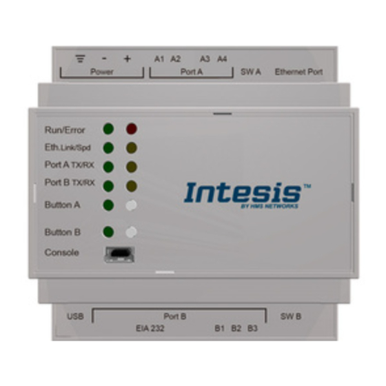
Page 7: Intesis Wmp Interface
2. Intesis WMP interface In this section, a common description for all Intesis WMP series gateways is given, from the point of view of the Home Automation system which is called from now on internal system. Connection with the Hitachi VRF system is also called from now on external system. -
Page 8: Connections
Connect a USB storage device (not HDD) if required. Check the user manual for more information. Ensure proper space for all connectors when mounted (see IMENSIONS © HMS Industrial Networks S.L.U. - All rights reserved https://www.intesis.com This information is subject to change without notice... -
Page 9: Power Device
Ethernet: Using the Ethernet port of Intesis. • USB: Using the console port of Intesis, connect a USB cable from the console port to the PC. © HMS Industrial Networks S.L.U. - All rights reserved https://www.intesis.com This information is subject to change without notice... -
Page 10: Set-Up Process And Troubleshooting
Ethernet port of the gateway and the Hitachi VRF installation connected to the corresponding port. Connectors, connection cables, PC for the Configuration Tool usage and other auxiliary material, if needed, are not supplied by Intesis for this standard integration. Items supplied by HMS Networks for this integration are: • Intesis gateway. -
Page 11: Configuration Tab
In this section it is possible to configure the different settings for the USB host port. 4.2.4. Home Automation (WMP) system configuration These are the settings available for the Home Automation system (WMP communication): © HMS Industrial Networks S.L.U. - All rights reserved https://www.intesis.com This information is subject to change without notice... -
Page 12: Hitachi Configuration
Active. If it’s active (checkbox at Unit xx), ranging from 1 to 64 indoor units that will be integrated (maximum number of units will depend on Intesis model) © HMS Industrial Networks S.L.U. - All rights reserved https://www.intesis.com This information is subject to change without notice... - Page 13 A progress bar will appear during the scan, which will take up to a few minutes. After scan is complected, detected units will be shown in available units as follows: Figure 4.6 Intesis MAPS Scan Hitachi Units window with scan results © HMS Industrial Networks S.L.U. - All rights reserved https://www.intesis.com This information is subject to change without notice...
-
Page 14: Signals
2.- Go to tab ‘Receive / Send’ of MAPS, and in Send section, press Send button. Intesis will reboot automatically once the new configuration is loaded. © HMS Industrial Networks S.L.U. - All rights reserved https://www.intesis.com This information is subject to change without notice... -
Page 15: Diagnostic
Signals Viewer to simulate the BMS behavior or to check the current values in the system. Figure 4.10 Diagnostic More information about the Diagnostic section can be found in the Configuraion Tool manual. © HMS Industrial Networks S.L.U. - All rights reserved https://www.intesis.com This information is subject to change without notice 15 / 24... -
Page 16: Set-Up Procedure
Intesis and the Home Automation hub or controller, check that those are operative: check the baud rate, the communication cable used to connect all devices and any other communication parameter. © HMS Industrial Networks S.L.U. - All rights reserved https://www.intesis.com This information is subject to change without notice... - Page 17 Home Automation (WMP) – Hitachi VRF Intesis User Manual r1.0 EN Figure 4.11 Enable COMMS © HMS Industrial Networks S.L.U. - All rights reserved https://www.intesis.com This information is subject to change without notice 17 / 24...
-
Page 18: Electrical & Mechanical Features
ON: 120 Ω termination active Switch B Off: 120 Ω termination inactive (default) (SWB) Position 2-3: ON: Polarization active Off: Polarization inactive (default) © HMS Industrial Networks S.L.U. - All rights reserved https://www.intesis.com This information is subject to change without notice 18 / 24... -
Page 19: Dimensions
Recommended available space for its installation into a cabinet (wall or DIN rail mounting), with space enough for external connections 100 mm (h) 100 mm (w) 130 mm (d) © HMS Industrial Networks S.L.U. - All rights reserved https://www.intesis.com This information is subject to change without notice 19 / 24... -
Page 20: Ac Unit Types Compatibility
7. AC Unit Types compatibility A list of Hitachi unit model references compatible with INMBSHIT---O000 and their available features can be found https://www.intesis.com/docs/compatibilities/inxxxhit001r000_compatibility © HMS Industrial Networks S.L.U. - All rights reserved https://www.intesis.com This information is subject to change without notice... -
Page 21: Error Codes For Indoor And Outdoor Units
Discharge Gas Failure of Thermistor, Temperature lncorrect Wiring, lncorrect Piping Connection, Expansion Valve Locking at Closed Position (Disconnect Connector) © HMS Industrial Networks S.L.U. - All rights reserved https://www.intesis.com This information is subject to change without notice 21 / 24... - Page 22 Wire, PCB Failure Activation of Low Compression Ratio Defective Compression (Failure of Protection Device Compressor of lnverter, Loose Power © HMS Industrial Networks S.L.U. - All rights reserved https://www.intesis.com This information is subject to change without notice 22 / 24...
- Page 23 NET Units are Connected to One System. lncorrect lndoor Unit Connection Number Setting 2 or more Switch Box Units are connected © HMS Industrial Networks S.L.U. - All rights reserved https://www.intesis.com This information is subject to change without notice 23 / 24...
- Page 24 Switch Box Unit The indoor units of different refrigerant! cycle is connected to Switch Box unit. lncorrect lndoor Unit Connection © HMS Industrial Networks S.L.U. - All rights reserved https://www.intesis.com This information is subject to change without notice 24 / 24...
Need help?
Do you have a question about the Intesis WMP Series and is the answer not in the manual?
Questions and answers