Advertisement
INSTALLATION INSTRUCTIONS FOR PART 99-9000
CF-104UD, SEA/HOS, SEA/HOS-W
KIT FEATURES
• DIN head unit provision
• Various mounting depths
KIT COMPONENTS
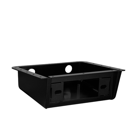
• A) Underdash housing • B) (8) Phillips screws
A
B
TOOLS REQUIRED
• Phillips screwdriver • Cutting Tool • Adjustable wrench
APPLICATIONS
Universal
99-9000
CAUTION: Metra recommends disconnecting the
negative battery terminal before beginning any
installation. All accessories, switches, and especially
air bag indicator lights must be plugged in before
reconnecting the battery or cycling the ignition.
NOTE: Refer to the instructions included with the
aftermarket radio.
Advertisement
Table of Contents

Related Manuals for Metra Electronics 99-9000


Summary of Contents for Metra Electronics 99-9000
- Page 1 INSTALLATION INSTRUCTIONS FOR PART 99-9000 APPLICATIONS Universal 99-9000 CF-104UD, SEA/HOS, SEA/HOS-W KIT FEATURES • DIN head unit provision • Various mounting depths KIT COMPONENTS • A) Underdash housing • B) (8) Phillips screws CAUTION: Metra recommends disconnecting the negative battery terminal before beginning any installation. All accessories, switches, and especially air bag indicator lights must be plugged in before reconnecting the battery or cycling the ignition.
-
Page 2: Dash Disassembly
99-9000 Dash Disassembly Kit Assembly All Vehicles DIN head unit provision 1. If an “open back” installation is 1. Slide the DIN cage into the kit desired (for additional depth), cut and secure by bending the metal the Underdash Housing along the locking tabs down. scored line and remove the rear 2. Slide the aftermarket head unit into portion of the Housing. (Figure A) the cage until secure. (Figure A) 3. Locate the factory wiring harness in the dash. Metra recommends using the proper mating adapter (Figure A) (Figure A) from Metra or AXXESS. - Page 3 99-9000 Kit Assembly DIN head unit provision (continued) 4. Place the head unit/kit assembly under the dash until the desired mounting location has been established. (Figure B) 5. Mark the screw holes onto the dash. 6. Re-connect the battery terminal and test the unit for (Figure B) proper operation. 7. Mount the head unit/kit assembly to the pre-marked holes on the dash with (8) Phillips screws supplied (If the back of the Underdash Housing was removed in Step #1, fewer screws will be used). (Figure C)
Need help?
Do you have a question about the 99-9000 and is the answer not in the manual?
Questions and answers