Table of Contents
Advertisement
Advertisement
Table of Contents

Subscribe to Our Youtube Channel
Related Manuals for SystemAir HHFlex


Summary of Contents for SystemAir HHFlex
- Page 1 HHFlex Air Handling Units Installation, operation and maintenance instructions...
-
Page 2: Checklist Of Start-Up Check Points
Content Safety considerations 1.1 - General 1.2 - Applications 1.3 - Instruction types 1.4 - Disposal of parts/materials Transport and lifting instructions 2.1 - General 2.2 - Transport and storage 2.3 - Roof edge protection during transport (outside installation) 2.4 - Offloading and hoisting 2.5 - Horizontal transport 2.6 - Storage 2.7 - Assembly... - Page 3 4.8.2 - Direct steam humidification 4.9 - Electric steam humidifier 4.9.1 - General, see 4.8.1 4.9.2 - Electric steam humidifier 4.10 - Water humidifiers 4.10.1 - General 4.10.2 - Spray humidifier 4.10.3 - Determining the quantity of spray water and the condensation factor 4.10.4 - Infrasonic humidification 4.11 - Fan 4.11.1 - Plug fans 4.11.2 - Frequency converters...
-
Page 4: Safety Considerations
HHFlex Air Handling Units Safety Considerations EU regulation 1253/2014 is part of the CE-marking. This regulation applies for: 1.1 - General • ‘ventilation unit (VU)’ means an electricity driven appliance equipped with at least one impeller, one The HHFlex air handling units (AHUs) have been designed and manufactured in accordance with the CE machine motor and a casing and intended to replace utilised directive. In order to guarantee safe operation and use of air by outdoor air in a building or a part of a building. - Page 5 HHFlex Air Handling Units Hot surfaces This pictogram indicates that there are components behind this access cover, door or panel that can cause serious burns when touched. The surfaces that may be hot are the heater surfaces. If there are special customer- specific components behind doors, access covers or panels that have hot surfaces and pose a potential risk, this is also indicated by this pictogram. Lifting prohibited This pictogram shows that no horizontal transport devices must be placed under this frame section, such as pallet lifters or the forks of fork lift trucks. It is also forbidden to place lifting devices for transport and storage under this frame element. Electrical voltage This pictogram indicates that there are electrical components behind this access cover, door or panel that may be dangerous for the user/installer. Only qualified personnel is permitted to carry out work on these components. For this work the regulations of the applicable international (e.g. IEC 61557, EN 50110 and Earthing ES 59009) and national (e.g. BS 7671) standards must be This pictogram indicates where the AHU can be earthed observed. The pictogram is attached to the access cover...
-
Page 6: Transport And Lifting Instructions
HHFlex Air Handling Units Transport and lifting instructions 2.1 - General • Transport and lifting of the AHU must always be in accordance with the instructions below. If these instructions are not observed, the unit may be ! Waarschuwing ! ! Warning ! irreparably damaged, and people in the immediate Voor openen deuren, ventilator Before opening the doors, switch uitschakelen, spanningsloos off and deenergise the fan and vicinity of the unit are endangered. Systemair B.V. does maken en uit laten lopen... - Page 7 HHFlex Air Handling Units To protect the roof edge on outside units that are wider 2.5 - Horizontal transport than 1500 mm, protection plates are added in place of For horizontal movement pallet lifters or transport skids the tie ropes to prevent distortion of the roof edge. can be placed under the installation frame or under the lifting bars. It is important that these support the lifting 2.4 - Offloading and hoisting points. At no time should the cross beams at the ends of Depending on the dimensions of the AHU and the the unit sections be used for jacking or tracking the AHU. situation on site, the AHUs are supplied in previously FOR HORIZONTAL TRANSPORT ALWAYS PROVIDE SUPPORT agreed transport sections. UNDER THE LIFTING POINTS. The use of bars as rollers can result in damage to the installation frame. Before proceeding with the transport and installation of the casing sections, always consult the applicable dimensional drawings that give the dimensions and weights of the sections, as well as the installation sequence. The weight is given on each transport section. Each transport section is equipped with a subframe with four lifting points. These points are marked with the label...
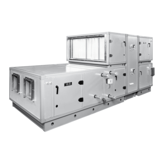
- Page 8 HHFlex Air Handling Units Example configuration of HHFlex with heat recovery wheel...
- Page 9 HHFlex Air Handling Units Legend Legend Dimensions Outdoor air intake damper Actuator, outdoor air damper W = width unit n x 160+98 Supply air filter Frequency converter, supply air fan H = height unit n x 160+98 Anti corrosion screen Main switch supply air fan H1 = height base frame in mm Pre-heater Pressure sensor, supply air fan Supply air fan Actuator, supply air damper The grey areas in the table indicate Heater (hot-water) Actuator, extract air damper standardised units.
- Page 10 10 | HHFlex Air Handling Units Start-up check points Function Components Check points Start-up Heaters Hot-water coil Correct connections Air vent the coil Leakage Frost protection thermostat connected Electric heater Check heater earth Check hatch earth Correct fuse size Check wiring diagram Check for possible condensate and if necessary dry the heater...
-
Page 11: Start-Up Instructions
| 11 HHFlex Air Handling Units Start-up instructions • It is recommended to use Europrofile connections (type E30) at the corner frame as well as at the duct to be connected. 4.1 - Casing The unit data, such as order number, position number etc. is given on the nameplate. • Europrofile connections are available in fixed lengths 4.1.1 - Casing panels and can be cut to the required length with a saw. Check the AHU panels for any damage. Any dirt or stains These profiles can easily be placed over the corner must be removed from the surface to prevent possible frame. Allow for a maximum profile height of 30 mm, long-term damage. Building debris left on the roof of so that ducts that are positioned one above the units installed inside and outside must be removed. Dirt other can be installed correctly. can be removed with water and a mild household soap •... -
Page 12: Outdoor Air Intake
12 | HHFlex Air Handling Units • The corner frame has a length of 40 mm and extends wind attacks at one of the openings. If these can be 32 mm beyond the external AHU dimension, as shown expected for the installation or geographical location, in the drawing below. try to minimise them with partitions. If there is any possibility that rain water can be drawn in, droplet eliminators are fitted with a suction grille in the outside air duct. • A pre-heater for the filters can be installed to prevent mist causing the filters to become too wet. The pre-heater will reduce the relative humidity of the air. Connection of the outdoor air intake duct Connection of the outdoor air intake duct to a unit with damper register: • The flexible connection protrudes beyond the external AHU dimension, as shown in the drawing • Connect a 500 mm long adapter piece to the corner below. frame of the air handling unit. • Insulate the inside of the complete adapter piece up to the unit panel. • Insulate the outside of the adapter piece so that there is a 250 mm overlap between inside and outside insulation. • The remainder of the adapter piece needs to be insulated on the outside, as shown in the drawing below. - Page 13 | 13 HHFlex Air Handling Units • Sufficiently insulate the cold water and condensate Connecting the outdoor air intake in one of the ways lines up to the AHU. depicted above prevents condensation on the corner • Sufficiently insulate air ducts with a possible air framework. temperature below the dew point of the air in the plant room, as described earlier. 4.1.7 - Assembly and placement of the air handling unit • E nsure that the floor in the room where the unit is For units that are installed outside, the following points installed is even and waterproof. The joints between the must be considered: parts must be covered with the sealing tape provided. • Always insulate air ducts with a possible air condition (temperature and relative humidity) with a dew point The sections can then be placed in the correct order.
- Page 14 14 | HHFlex Air Handling Units 4.2.2 – Recirculation damper 4.4 - Heaters • The damper must always be closed during power 4.4.1 - General cuts and when the unit has stopped. • Always use gloves while carrying out maintenance or • If a recirculation damper is used, then both the repairs on the heater element to prevent cuts. outdoor intake and the exhaust opening must be • Always wear safety glasses while working on the fitted with a damper. heater element. • If the recirculation damper is used in a modulating • The fins and the pipes can reach temperatures that manner, the authority must be guaranteed depending can cause burns. During maintenance work always on the external pressures on the other opening. The wear gloves that provide protection against tempera- authority of the recirculation damper can be increased tures up to at least 70°C.
-
Page 15: Electric Heater
| 15 HHFlex Air Handling Units • The warning label for electrical voltage is attached to 4.4.1.1 - Coils containing glycol the inspection hatch. If coils are filled with a water/glycol mixture, this requires extra attention. • Glycol can react violently with strong oxidation solutions. • When working on the coil, always check which medium is used. Before adding anything to the heat exchange medium, always check with the installer. • Always wear safety glasses and gloves. • Do not smoke or use an open flame. • The earth warning label is attached to the inside of • When sizing the expansion tank take the higher heat the heater and the inspection hatch. transfer coefficient into account (± 25% larger). • Watertight seals are not always tight for water glycol mixtures. It is therefore better to use weld/solder connections. • Water/glycol causes increased sludge formation. - Page 16 16 | HHFlex Air Handling Units • Never exceed the maximum operating pressure. 4.4.3 - Steam heaters • Check the connections on the dimensional drawing. ATTENTION: • Ensure that the coil has been fully purged. • Steam heaters connected to the pipes must always • Check connections for leakage. be compression-tested by trained personnel and comply with the PED guideline. Compression testing is CAUTION: When the coils are drained, no water must the responsibility of the installer. Pipes must always remain in the circuits to prevent freezing at temperatures be insulated and are the responsibility of the installer. below zero. • The operation of the steam heater must be con- nected to the operation of the fan. If the fan stops, • If a changeover coil is supplied by a heat pump, the stop the supply to the steam heater immediately. installation must be designed to compensate for the • Steam heaters have surface temperatures that required heat during the system heat pump defrost exceed 100°C. The steam intake must be done by...
- Page 17 | 17 HHFlex Air Handling Units • Check that the (negative or gauge) pressure corres- • Check if the droplet eliminator after the cooler has ponds to the siphon type installed. been correctly installed. • The outlet of the siphon trap connected to the drain • Check if fins have been bent during transport. must not be under pressure. • Correctly straighten the fins. • The fins will only work correctly after several days in dehumidification mode. • Start up the cooling coil by opening the shut-off valves and switching on the controller. After several days of cooling operation check the condensate drain and operation of the plastic siphon. • If necessary clean the siphon. 4.5.2 - Glycol in elements, see 4.4.1.1 •...
- Page 18 18 | HHFlex Air Handling Units • Check if the motor and the rotation monitor have If desired/necessary, the heat recovery wheel is fitted been correctly connected (5 mm play between with a sensor to protect the heat exchanger against sensor and detection point on the wheel). freezing. If dampers are present, the control system • Check if the controller has been correctly connected must open and close the dampers at the correct time to and set in accordance with the supplier instructions. prevent freezing of the plate heat exchanger. The instructions from the controller supplier apply. • Ensure that the rotor speed has been correctly set 4.8 - Direct steam humidification The HHFlex condensation rotor must have a 4.8.1 - General maximum speed of 10 min ; a sorption rotor must •...
- Page 19 | 19 HHFlex Air Handling Units • Clean the dirt collector sieve and check the condensate 4.10 - Water humidifiers exhaust several days after commissioning the unit. In 4.10.1 - General case of cabinets with under-pressure, the operation • Bacteria may grow in open water. Ensure correct of the under-pressure siphon must be checked with maintenance to prevent Legionaire’s Disease. a non-return valve. • The connection of the replenishment water and the • A maximum hygrostat must be fitted in order to prevent drainage of the condensate water must comply with excessive humidification in the AHU. See 4.8.1. local regulations. • The connection of the steam pipe to the pipe must • The circulation pump of the humidifier can only be be tension-free in order to prevent distortion of the started when the fan is in operation. It will not...
- Page 20 20 | HHFlex Air Handling Units • Determine the spray water amount with a known • The following sticker is applied to the control box. maximum of water to be evaporated and a selected thickening factor. Qs = qv qt = qv + qs where: = thickening factor (see below) 4.11 - Fan = supply water amount = quantity of water to be evaporated = spray water amount The pH value of the spray water must not be lower than 5 Remove after or higher than 10.
- Page 21 | 21 HHFlex Air Handling Units belt tension or to remove the fan belts temporarily. The fan motor must have a power supply of 230 V, 3 When the fans are restarted, the belt tension has to ph, 50 Hz or 400 V, 3 ph, 50 Hz. The connection must be be reset to the specified value. This type of damage made with short circuit protection (fuses) and a thermal can also be prevented by controlled rotation of the motor safety switch, matched to the nominal current fan impeller. This is recommended for direct-drive of the motor. The motor can also be protected against fans. overheating by three series-connected PTC thermistor • Check if the flexible connection is correctly installed. fuses, installed in the windings. If a frequency converter is • If used, check the pressure switch and set the correct used, the thermistors must be connected to the converter. pressure. • Check the operation of the main switch. CAUTION: While working on the fan the switch has to be locked open. • The warning pictograms on rotating parts, electrical voltage and opening doors are attached to the door. Thermal motor fuse Before connecting the power supply please check the diagrams on the next page to ensure that they agree with the data on the motor name plate and the data in the technical documentation. ! Waarschuwing !
- Page 22 22 | HHFlex Air Handling Units Connection diagrams: connection of the power supply cable and of the terminals on the terminal strip. Motor with the name plate data: 230 V/400 V - Y/Δ Direct mains connection with a voltage between two phases of: Indirect mains connection Y/Δ...
- Page 23 | 23 HHFlex Air Handling Units 4.11.2 - Frequency converters 4.11.3 - Plug fans with integrated EC motors It is recommended to install a frequency converter with an For EC motors both electronic commutation and speed integrated operating switch. If a separate operating switch control are integrated in the motor as standard. The motor protection class is IP54 and the thermal class is THCL155. is installed on the unit and near the frequency converter, this can be located in the supply voltage for the frequency The motors can be single-phase 230 V or three.phase 400 V. converter. If the frequency converter is not installed near the unit/operating switch, the operating switch can be To achieve the correct motor speed a 0-10 V control placed in the control power circuit, that switches the signal should be supplied to the motor. The technical specification of the unit shows the exact value (in V) to supply voltage to the frequency converter via a relay. To connect the frequency converter, please refer to the reach the correct motor speed. wiring diagram for the converter installed. Ensure that the EMC directives are observed and pay attention to the As an option the motor can be factory set so that 10 V is shielded cables. the motor speed at the actual point of operation. The frequency converter must always be correctly set to A second option is to use a motor with an integrated suit the motor and type installed. Observe the instructions Modbus module. In this case the motor can be externally...
- Page 24 24 | HHFlex Air Handling Units To connect a single-phase 230 V or the three-phase 400 V motor the following connection diagram is applicable. ECblue Basic (_ _ _ _ _-_I_.D_._ _ _ _), (_ _ _ _ _-_I_.G_._ _ _ _) Contact rating Kontaktbelastung Contact rating max AC 250 V 2 A max. AC 250 V 2 A 24V 10V GND D1 L3/N Line voltage g rating plate...
-
Page 25: Maintenance Checklist
| 25 HHFlex Air Handling Units Maintenance Checklist 5.1 - Checklist of check points and maintenance intervals The unit data, such as order number, position number etc. description of the individual components. is given on the nameplate. WARNING: Remember to de-energise all components and The checklist contains a general overview of a planning to ensure that the fan has stopped rotating, before the that facilitates the inspections and maintenance of the doors and access covers are opened before inspections AHU. On the following pages there is a more detailed and maintenance take place. Check points and maintenance intervals... -
Page 26: Outside Installation
26 | HHFlex Air Handling Units Steam humidification electric Connection and appendages Leakage/operation Electric components Operation Boiler Scaling on the electrodes Spray humidification Sprayers Operation Infrasonic humidifier Hoses Connections/tears Sprayers Operation Pressostat Operation/max. pressure Coil filter Contamination Operating pressure Bearings (larger types) Lubrication/wear... - Page 27 | 27 HHFlex Air Handling Units 6.7 - Outdoor air intake 6.9 - Heaters The outdoor air intake is contaminated by pollution taken 6.9.1 - Hot-water coil in with the air. Observe the maintenance interval to avoid irreparable damage of the panels. Clean the outdoor air ATTENTION: For general comments, see 4.4.1 intake well and repair damage as described in point 6.2.1. Ensure that no moisture (droplets) is taken in. If there is • Dirt on the finned surface reduces the capacity of the still moisture, ensure that this is corrected by changing the heater. outdoor air intake duct. • Check the air intake once a year for contamination, and if necessary clean with compressed air against 6.8 - Filters the direction of the air flow or clean the air intake ATTENTION with a vacuum cleaner.
- Page 28 28 | HHFlex Air Handling Units • The following label is attached to indicate a hot surface. 6.11 - Heat recovery wheel • Contamination on the finned surface reduces the capacity of the heat recovery wheel. • Check the rotor once a year for contamination, and if necessary clean with compressed air. Check the rotor speed and compare it with the design data. • Check the operation of the rotation monitor. Depending on the rotor material the wheel can absorb moisture. • The warning label for electrical voltage is attached to When stationary the wheel will become moist on the inspection hatch. one side and therefore heavier. The rotor speed can be set to intermittent in the controller so that the wheel will rotate “x” times per time unit. • The rotor bearings are lubricated for life and do not require maintenance. The drive motor is accessible via an inspection cover. • The V-belt is automatically tensioned by a spring loaded rocking base on which the motor is installed. • The earth warning label is attached to the inside of New belts expand a lot in the beginning. Check after the heater and the inspection hatch.
- Page 29 | 29 HHFlex Air Handling Units • Switching the humidifier on and off, can produce 6.14.2 - Spray humidifier scaling in the spray pipes which may affect their • Check the correct functioning of the float seal for the operation. It is therefore necessary to regularly check replenishment water every week. Scaling and sludge and clean these spray pipes. formation can have a detrimental effect on the opera- tion of the float tap. The water level in the water 6.15 - Fan container must always be kept at the correct level 6.15.1 - General without water overflowing into the funnel-shaped CAUTION: The air flow may cause stationary parts to move overflow. When the circulation pump is stopped, the (even if the fan is switched off)! level is 5 mm under the overflow. Check the spray water amount every week during the humidification CAUTION: While working on the fan, the switch must be season. The salt concentration (thickening) in the locked open. reservoir depends directly on the effective operation of the spray tap. Regularly check the quality of the Before switching off the fan always check if an electric water in the reservoir. During the humidification heater is installed. If this is the case, the electric heater season this check must be made monthly. must always be switched off first. The fan must continue •...
- Page 30 30 | HHFlex Air Handling Units The belt tension is calculated for each transmission. If the WARNING: Remember to de-energise all components and belt tension is too high it can result in bearing wear and to ensure that the fan has stopped rotating, before the vibration. If it is too low it can result in belt slippage and doors and access covers are opened before inspections pulley and belt wear. and maintenance take place. Sequence for installation of new belts: 6.16 - Silencers...
- Page 32 Fax +31 (0) 416 341795 www.systemair.nl Systemair B.V. participates in the Eurovent Certification programme. Products are as listed in the Eurovent Directory of Certified Products. The manufacturer reserves the right to change the specification without prior notice. Manufactured by: Systemair B.V., Waalwijk, The Netherlands.
Need help?
Do you have a question about the HHFlex and is the answer not in the manual?
Questions and answers