Table of Contents
Advertisement
Quick Links
Advertisement
Table of Contents

Subscribe to Our Youtube Channel
Related Manuals for SystemAir HRU 1500


Summary of Contents for SystemAir HRU 1500
- Page 1 New Zealand USER’S MANUAL User's Manual HRU 1500/2500/3500...
-
Page 2: Table Of Contents
THE PRODUCT MUST BE DISPOSED SEPARATELY AT THE END OF ITS SERVICE LIFE. DO NOT DISPOSE THE UNIT AS UNSORTED DOMESTIC WASTE. www.systemair.nz... -
Page 3: Safety Requirements
• Ensure that the appliance is switched off from the supply mains before removing the guard. • Precautions must be taken to avoid the back-flow of gases into the room from the open flue of gas or other fuel-burning appliances. HRU 1500/2500/3500 User Manual... -
Page 4: Purpose
HRU X P B EC R А** Automation type Service side L – left R – right Motor type EC – electronically commutated Additional components B – bypass Spigot orientation P - suspended mounting, horizontal spigot orientation. Rated air flow [m Unit type www.systemair.nz... -
Page 5: Technical Data
HRU 1500 1340 520 1726 1700 HRU 2500 1610 350 HRU 3500 1350 1960 1932 See the complete list of the technical data for the unit in the technical data sheet included in the delivery set. HRU 1500/2500/3500 User Manual... -
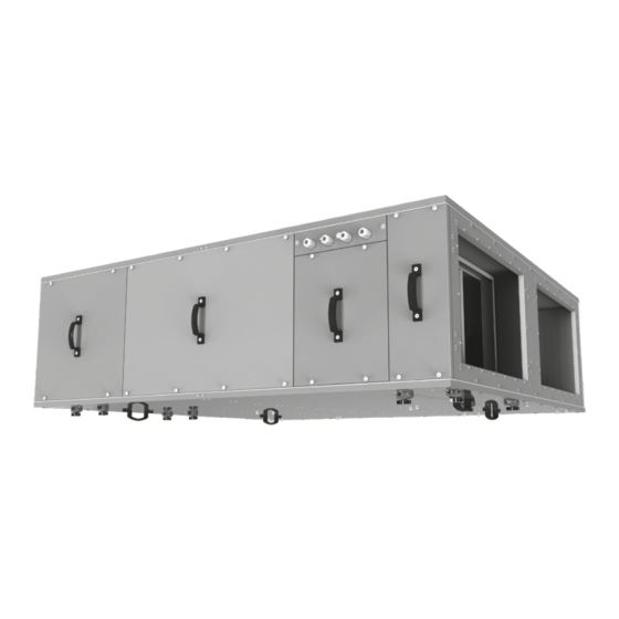
Page 6: Unit Design
5 – panels for access to the fans (located at the bottom of the unit) 6 – panels for access to the filters (located at the bottom of the unit) Panels 1-5 are fixed with screws. Panels 6 are secured with thumbscrews. www.systemair.nz... - Page 7 Three position ball valve with an Belimo R3020-4-B1+ Belimo R3020- electric actuator LR24A-SR 6P3-B1+ LR24A-SR Liquid mixing kit for the water heater USVK 3/4-4 USVK 3/4-6 Differential pressure switch DTV 500 Flexible connector VVG AV 600x350 Silencer SR 600x350 HRU 1500/2500/3500 User Manual...
-
Page 8: Mounting And Set-Up
While choosing fasteners consider the material of the mounting surface as well as the weigh of the unit. Fasteners for installation should be selected by a qualified technician. When installing the unit, it is necessary to ensure its slope of at least 3° towards the drainage pipes. www.systemair.nz... - Page 9 1 – drain spigot 2 – connecting pipe 3 – U-trap 4 – sewage system min 3° Make sure that the water flows into the sewage system before starting operation. Fill up the U-trap with water before using it. HRU 1500/2500/3500 User Manual...
-
Page 10: Wiring Diagram
WIRING DIAGRAM HRU1500 - 3500 HRU 1500-3000 230V/2A 0-10V 0-10V 0-10V 230V/2A 230V/2A 230V/2A CO2 IN CONTROL PANEL 10V IN NKD 10V 230V/1PH DESIGNATION NAME CABLE TYPE CONTACT TYPE SWITCH VOLTAGE CONTACT FROM FIRE PANEL 2 X 0.75 2A, 230V, AC FIREPLACE MODE INPUT 2 X 0.75... -
Page 11: Technical Maintenance
Access to filters through side service panels Remove the service panels. Unscrew the two thumbscrews securing the Remove the filter elements. retaining plate. Access to filters through lower service panels Remove the service panels. Remove the filter elements. HRU 1500/2500/3500 User Manual... -
Page 12: Storage And Transportation Regulations
The unit must be transported only in the working position. • Avoid sharp blows, scratches, or rough handling during loading and unloading. • Prior to the initial power-up after transportation at low temperatures, allow the unit to warm up at operating temperature for at least 3-4 hours. www.systemair.nz... - Page 13 HRU 1500/2500/3500 User Manual...
- Page 14 www.systemair.nz...
- Page 15 HRU 1500/2500/3500 User Manual...
- Page 16 Systemair New Zealand Ltd Ph 0800 100 326 nzsales@systemair.nz www.systemair.nz...
Need help?
Do you have a question about the HRU 1500 and is the answer not in the manual?
Questions and answers