Mitsubishi Electric FR-A7AX E kit-SC Instruction Manual
16-bit digital input function
Hide thumbs
Also See for FR-A7AX E kit-SC:
- Instruction manual (33 pages) ,
- Instruction manual (45 pages)
Table of Contents
Advertisement
Quick Links
Download this manual
See also:
Instruction Manual
Advertisement
Table of Contents

Related Manuals for Mitsubishi Electric FR-A7AX E kit-SC


Summary of Contents for Mitsubishi Electric FR-A7AX E kit-SC
- Page 1 INVERTER Plug-in option FR-A7AX E kit-SC INSTRUCTION MANUAL 16-bit digital input function PRE-OPERATION INSTRUCTIONS INSTALLATION AND WIRING CONNECTION DIAGRAM AND TERMINAL PARAMETERS...
- Page 2 Thank you for choosing this Mitsubishi Inverter plug-in option. SAFETY INSTRUCTIONS This Instruction Manual gives handling information and precautions for use of this equipment. Incorrect handling might cause an unexpected fault. Before using the equipment, please 1. Electric Shock Prevention read this manual carefully to use the equipment to its optimum.
- Page 3 2. Injury Prevention 3) Usage WARNING CAUTION • Do not modify the equipment. • The voltage applied to each terminal must be the ones • Do not perform parts removal which is not instructed in this specified in the Instruction Manual. Otherwise burst, damage, etc.
-
Page 4: Table Of Contents
— CONTENTS — 1 PRE-OPERATION INSTRUCTIONS Unpacking and Product Confirmation .....................1 1.1.1 Product confirmation............................1 Parts ..............................2 Specifications.............................3 2 INSTALLATION AND WIRING Pre-Installation Instructions ......................4 Installation Procedure ........................4 Wiring..............................9 3 CONNECTION DIAGRAM AND TERMINAL Connection Diagram........................12 Internal Block Diagram........................14 Terminals ............................15 Code Input Example ........................16 4 PARAMETERS Parameter List ..........................17... -
Page 5: Pre-Operation Instructions
PRE-OPERATION INSTRUCTIONS Unpacking and Product Confirmation Take the plug-in option out of the package, check the product name, and confirm that the product is as you ordered and intact. This product is a plug-in option for the FR-E700-SC series (safety stop function model) 1.1.1 Product confirmation Check the enclosed items. -
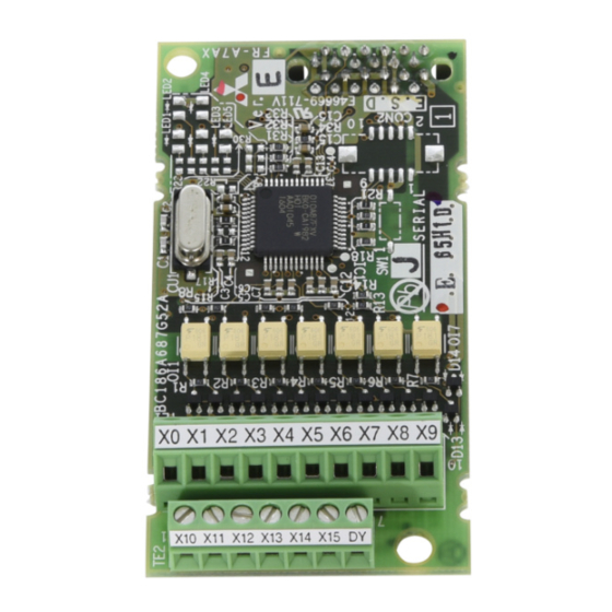
Page 6: Parts
PRE-OPERATION INSTRUCTIONS Parts Mounting Terminal Front view Rear view hole block Mounting hole Connector Mounting hole Connect to the inverter option connector Terminal layout (Refer to page 5, 7.) -
Page 7: Specifications
PRE-OPERATION INSTRUCTIONS Specifications (1) Digital input signal type BCD code 3-digit or 4-digit Binary 12-bit or binary 16-bit (2) Selection of digital input signal Select from the operation panel or parameter unit. (3) Input current 5mA(24VDC) for each circuit (4) Input specifications Relay contact signal or open collector input (5) Adjustment function ⋅... -
Page 8: Installation And Wiring
INSTALLATION AND WIRING Pre-Installation Instructions Make sure that the input power of the inverter is off. CAUTION With input power on, do not install or remove the plug-in option. Otherwise, the inverter and plug-in option may be damaged. For prevention of damage due to static electricity, touch nearby metal before touching this product to eliminate static electricity from your body. - Page 9 INSTALLATION AND WIRING Inverter with one front cover (1) Remove the front cover from the inverter. (For removing the front cover, refer to the FR-E700 series instruction manual.) (2) Remove the PU cover from the front cover. Open the PU cover with a driver, etc. and remove it in the direction of arrow as shown below.
- Page 10 INSTALLATION AND WIRING (6) Remove the PU cover provided on the front cover for plug-in option and mount the other PU cover, which was removed in (2). (7) Loosen the terminal screws and insert the wires into the terminals. After that, fasten the terminal screws to the recommended tightening torque.
- Page 11 INSTALLATION AND WIRING Inverter with front covers 1 and 2 (1) Remove the front cover 1 and 2 from the inverter. (For removing the front cover, refer to the FR-E700 series instruction manual.) (2) Remove the PU cover from the front cover 2. For removing the PU cover, refer to page 5.
- Page 12 INSTALLATION AND WIRING (4) Junction (4) Hexagon connector spacer (4) Plug-in option connector of inverter Front cover for plug-in option Replace Installation completed (4) Spacer for (6) Mounting screws plug-in option (short) mounting (6) Mounting screw (long)
-
Page 13: Wiring
INSTALLATION AND WIRING Wiring (1) Untwist the twisted pair shielded cables after stripping its sheath. Shield Also, perform protective treatment of the shield to ensure that it will not (perform protective treatment) make contact with the conductive area. Sheath Twisted pair Strip off the sheath about the size as in the right figure. - Page 14 INSTALLATION AND WIRING REMARKS • Information on blade terminals Commercially available product examples (as of Jan. 2010) Wire Size Blade Terminal Model Terminal Maker Screw Size With insulation sleeve Without insulation sleeve Phoenix Contact 0.3, 0.5 AI 0,5-6WH A 0,5-6 Co.,Ltd.
- Page 15 INSTALLATION AND WIRING POINT If a hook of the front cover for plug-in option impedes wiring, cut the hooks off and perform wiring. Cut off hooks at the bottom of the Cut off with a option cover. nipper, etc. (Cut off so that no portion is left.) REMARKS The protective structure (JEM1030) is the open type (IP00).
-
Page 16: Connection Diagram And Terminal
CONNECTION DIAGRAM AND TERMINAL Connection Diagram Relay contact signal input (sink logic Open collector signal input (sink logic AY41 type transistor FR-A7AX FR-A7AX output unit Unit's place Unit's place Ten's place Ten's place Hundred's place Hundred's place Thousand's place Thousand's place Reading command Inverter Inverter... - Page 17 CONNECTION DIAGRAM AND TERMINAL REMARKS • As the input signals are at low level, use two parallel micro signal contacts or a twin contact for relay contact inputs to prevent a contact fault. Micro signal contacts Twin contacts • A transistor of the following specifications should be selected for the open collector signal: Electrical characteristics of the transistor used ⋅...
-
Page 18: Internal Block Diagram
CONNECTION DIAGRAM AND TERMINAL Internal Block Diagram The following is the internal block diagram of the FR-A7AX. Connector Controller... -
Page 19: Terminals
CONNECTION DIAGRAM AND TERMINAL Terminals Terminal Terminal Description Location Symbol Digital signal input terminal (frequency setting signal terminal) Input the digital signal at the relay contact or open collector terminal. (Refer to page 12.) For the digital signal input, you can choose either the BCD code X0 to X15 input or binary input. -
Page 20: Code Input Example
CONNECTION DIAGRAM AND TERMINAL Code Input Example The following explains examples of terminal status and input value at BCD code input and binary input. Example: when the input value is 6325 Example: when the input value is AB65 BCD Code Input Binary Input Input Terminal... -
Page 21: Parameters
PARAMETERS Parameter List The following parameters are used for the plug-in option (FR-A7AX). The FR-A7AX does not function with the factory setting. When a value other than 9999 is set in Pr. 304, " " digital input is enabled. Set the following parameters according to applications. Minimum Parameter Initial... -
Page 22: Parameter Setting
PARAMETERS Parameter Setting 4.2.1 Selection of input method (Pr. 304) Parameter Initial Name Setting Range Number Value Digital input and analog input compensation enable/disable selection * 0, 1, 10, 11, 9999 9999 Pr. 304 Setting BCD Code Input Binary Input ⎯... -
Page 23: Read Timing Operation Selection (Pr. 305)
PARAMETERS 4.2.2 Read timing operation selection (Pr. 305) Parameter Initial Name Setting Range Number Value Read timing operation selection 0, 1, 10 Pr. 305 Setting Filter Description The set frequency data entered from the digital signal input terminals (X0 to X15) is 0 (initial value) Without always imported independently of whether the DY signal is on or off. - Page 24 PARAMETERS (2) How to use the DY signal (when "1" is set in Pr. 305) 1ms or more 1ms or more Digital signal input (terminal X0 to X15) 20ms or more necessary Data read timing signal (terminal DY) REMARKS • When Pr. 305 = "1", each terminal from X0 to X15 is all recognized as off when the inverter is turned on in terminal DY off status.
-
Page 25: Bias And Gain Adjustment (Pr. 300, Pr. 301, Pr. 302, Pr. 303)
PARAMETERS 4.2.3 Bias and gain adjustment (Pr. 300, Pr. 301, Pr. 302, Pr. 303) Parameter Name Setting Range Initial Value Number BCD input bias 0 to 400Hz BCD input gain 0 to 400Hz, 9999 60Hz (50Hz) BIN input bias 0 to 400Hz BIN input gain 0 to 400Hz, 9999 60Hz (50Hz) - Page 26 PARAMETERS (2) Gain adjustment The gain may be set in either of the following two ways: How to set the output frequency when the digital input signal is "999 or 9999" (BCD code input), and "FFF or FFFF " (binary input). ⋅...
- Page 27 PARAMETERS How to set the BCD code or binary value as the output frequency setting When "9999" is set in Pr. 301 (BCD code input) or Pr. 303 (binary input), the digital input value is set as the output frequency. (For example, to set the output frequency to 120Hz when the BCD code input is "...
-
Page 28: Digital Input Unit Selection (Pr. 329)
PARAMETERS 4.2.4 Digital input unit selection (Pr. 329) Parameter Name Setting Range Initial Value Number Digital input unit selection 0, 1, 2, 3 When "9999" is set in Pr. 301 or Pr. 303, the increments when the digital signal is set as output frequency can be set. -
Page 29: Instructions
PARAMETERS Instructions (1) Acceleration/deceleration time When the frequency is set with the digital input signal, the acceleration/deceleration time is the period of time required to reach the Acceleration/deceleration reference frequency set in Pr. 20. This is the same as when using the analog signal input. (2) There are the following restrictions on the digital input signal: When the signal is used to enter a BCD code, 0A to 0F... - Page 30 REVISIONS *The manual number is given on the bottom left of the back cover. Print Date *Manual Number Revision First edition Aug. 2011 IB(NA)-0600466ENG-A IB(NA)-0600466ENG-A...
- Page 31 INVERTER HEAD OFFICE: TOKYO BUILDING 2-7-3, MARUNOUCHI, CHIYODA-KU, TOKYO 100-8310, JAPAN IB(NA)-0600466ENG-A(1108) MEE Printed in Japan Specifications subject to change without notice.
Need help?
Do you have a question about the FR-A7AX E kit-SC and is the answer not in the manual?
Questions and answers