Table of Contents
Advertisement
Advertisement
Table of Contents

Related Manuals for Meridian Seed Express 275 DX


Summary of Contents for Meridian Seed Express 275 DX
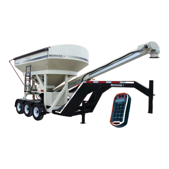
- Page 1 SEED EXPRESS FOR OWNERS AND OPERATORS OF THE 275 DX / 375 DX...
- Page 3 PRODUCT WARRANTY R E G I S T R A T I O N F O R M WARRANTY REGISTRATION This form must be filled out by the dealer and signed by both the dealer and the customer at the time of delivery.
- Page 5 2902 Expansion Blvd. Storm Lake, IA 50588 Phone: 712-732-1780 Fax: 712-732-1028 CERTIFICATE OF ORIGIN LICENSING INFORMATION Date: ____/___/_______ SOLD TO: DEALER ___________________________Business ___________________________Business ___________________________Contact ___________________________Contact ___________________________Address ___________________________Address ___________________________City, State, Zip ___________________________City, State, Zip TENDER MODEL # _________________________________________________________ TENDER WEIGHT __________________________________________________________ TENDER SERIAL # __________________________________________________________ TRAILER MODEL # _________________________________________________________ TRAILER SERIAL #* _________________________________________________________...
- Page 7 IMPORTANT INFORMATION SERIAL NUMBER LOCATION PATENT INFORMATION Report the serial number of your Meridian 275 DX or 375 DX Seed Express and engine when ordering parts or requesting service or other information. The serial number plates are located where indicated. Please mark the number in the space provided for easy reference.
-
Page 8: Table Of Contents
CONTENTS 1. INTRODUCTION ............11 1.1 Congratulations . - Page 9 8. STORAGE ............. . . 42 8.1 General Information .
- Page 10 13. WARRANTY ............58 13.1 Warranty Statement.
-
Page 11: Introduction
1. INTRODUCTION 1.1 CONGRATULATIONS 1.2 OPERATOR ORIENTATION Congratulations on your choice of a Meridian The directions left, right, front and rear, as Manufacturing Group 275 DX or 375 DX Seed mentioned throughout this manual, are as seen Express Bulk Seed Tender to complement your seed from the truck drivers’... -
Page 12: Safety
If you have any questions not answered in this manual, require additional copies of the manual, or the manual is damaged, please contact your dealer or Meridian Manufacturing Group, 2902 Expansion Blvd., Storm Lake, Iowa, 50588, toll free 1-800-437-2334, phone (712) 732-1780, or fax (712) 732-1028. - Page 13 YOU are responsible for the SAFE operation and 2.1 General Safety maintenance of your Meridian Manufacturing Read and understand the Operator’s Group bulk seed tender Model 275 DX or 375 DX Manual and all safety signs before Seed Express delivery system. YOU must ensure operating, maintaining, adjusting, filling, ...
-
Page 14: Equipment Safety Guidelines
2.2 EQUIPMENT SAFETY 8. In addition to the design and configuration GUIDELINES of this implement, including Safety Signs and Safety Equipment, hazard control and 1. Safety of the operator and bystanders is accident prevention are dependent upon the one of the main concerns in designing and awareness, concern, prudence, and proper developing a machine. -
Page 15: Safety Signs
2.4 SAFETY SIGNS PROLONGED EXPOSURE TO LOUD NOISE MAY CAUSE PERMANENT Keep safety signs clean and legible at HEARING LOSS! Motors or equipment all times. Replace any safety sign or can be noisy enough to cause instruction sign that is missing or not permanent or partial hearing loss. -
Page 16: Maintenance Safety
Stop engine, remove ignition key, and wait for all moving parts to stop before STOP servicing, repairing, adjusting, loading, filling, or unplugging. Always use personal protection devices, such as eye, hand, and hearing protectors, when Keep working area clean and performing any service or maintenance. free of debris to prevent slipping or tripping. -
Page 17: Storage Safety
2.9 STORAGE SAFETY 2.11 REFUELLING SAFETY 1. Store the unit in an area away from human Handle fuel with care. It is highly activity. flammable. 2. Do not permit children to play on or around the A llow engine to cool for five minutes stored machine. -
Page 18: Sign-Off Form
2.13 SIGN-OFF FORM Make these periodic reviews of SAFETY and OPERATION a standard practice for all of your Meridian Manufacturing Group follows the general equipment. We feel an untrained operator is Safety Standards specified by the American unqualified to operate this machine. Society of Agricultural Engineers (ASAE) and Occupational Safety and Health Administration A sign-off sheet is provided for your record keeping (OSHA). -
Page 19: Safety Sign Locations
3. SAFETY SIGN LOCATIONS The types of safety signs and locations on the equipment are shown in the following pages. Good SAFETY AWARENESS requires that you familiarize yourself with the various safety signs, the type of warning and the area, or a particular function related to that area. - Page 20 3. Product Serial Number Decal 1. CAUTION — Read and Understand (#19934) 4. WARNING — Rotating Parts (#19936) 2. NOTICE — Product Warranty (#19944)
- Page 21 5. WARNING — Fall Hazard (#19939) 6. WARNING — Hot Surface (#20088) 7. WARNING — Pinch Point (#19935) 8. DANGER — Pinch Point (#20087)
-
Page 22: Specifications
4. SPECIFICATIONS 4.1 OVERALL SEED TENDER SPECIFICATIONS 275 Seed 375 Seed Express Express l l a c t i 24' - 6" 24' - 6" h t i c t i 24' - 6" 24' - 6" l l a "... -
Page 23: Bolt Specifications
4.2 BOLT SPECIFICATIONS WARNING The torque value for bolts and capscrews are identified by their head markings. Replacing higher “Grade” bolts (Grade 8) with lower Grade bolts (Grade 5) will lead to equipment failure and can result in injury or death. Always use replacement bolts with the same Grade markings as the removed bolt. -
Page 24: Machine Components And Controls
5. MACHINE COMPONENTS AND CONTROLS 5.1 COMPONENT NOMENCLATURE AND LOCATION The Meridian 275 DX or 375 DX Seed Express models are designed as bulk seed transfer units to transfer large amounts of seed into a planter or drill. Large bulk seed containers are loaded into the seed tender compartments (1 &... -
Page 25: Engine And Controls
5.2 ENGINE AND CONTROLS 3. Fuel Shut-Off Valve Each engine is equipped with a valve between A Honda engine is used with the unit. Always ® the fuel tank and the carburetor. Slide the fuel read the engine Operator’s Manual supplied valve toward the block to turn ON and away with the seed tender for the detailed operating for OFF. -
Page 26: Control System Functions
5.3 CONTROL SYSTEM FUNCTIONS Conveyor Start and Stop (5) This toggle switch starts and stops the conveyor The MEGA REMOTE system is a state-of-the-art belt. Press the toggle switch UP to start the microprocessor based Radio Frequency (RF) conveyor. Press the toggle switch DOWN to stop control system. -
Page 27: Setting The Weight To Dispense
Tare (12) 3. Press the Auto Reset button on the remote To “Tare” or zero the scale when the receiver transmitter. The unit monitors the weight display is on the main display page showing the of seed being dispensed. As the weight weight, press and hold the tare push button on approaches the desired Weight To Dispense, either the remote transmitter or the receiver for... -
Page 28: Wireless Remote Transmitter
5.4 WIRELESS REMOTE 5.4.1 Functions of Keypad Buttons TRANSMITTER Use the buttons on the keypad to operate the Each radio remote transmitter is designed to desired functions of the seed tender. operate with a unique radio ID code and RF channel sequence. -
Page 29: Display Panel
5.4.2 Display Panel CONV (6) This Conveyor button extends and retracts the conveyor. Press the EXT button to extend the conveyor. Press the RET button to retract the conveyor. GATE 2 (7) The Slide Gate 2 buttons open and close the slide (1) Weight Displayed in Pounds. -
Page 30: Display Messages
Pressing the POWER button turns the remote displayed. transmitter ON and displays the message “Meridian Mega Remote”. If the “NO LINK” message appears, the remote transmitter is not communicating with the control panel on the seed tender. Make sure the ON/OFF key switch is in the ON position. -
Page 31: Pre-Operating Instructions
6.1.1 Before Starting specified oil. 1. Read and follow the instructions in the Honda ® engine and the Meridian Operator’s Manuals. 2. Review and follow Set-Up Instructions and the Pre-operation Checklist before starting machine. 3. Initially check wheel bolt torque and then again at 10, 25, and 50 miles. -
Page 32: Pre-Operation Checklist
6.2 PRE-OPERATION CHECKLIST 9. Check the fluid level in the hydraulic tank. Add fluid as needed. Efficient and safe operation of the Meridian Bulk Seed Tender system requires that each operator 10. Start the engine and check the filter status reads and follows the operating procedures and all indicator. Replace the filter if indicated. related safety precautions outlined in this section. 11. Check the tension of the delivery belt. Follow... -
Page 33: Operation
7. OPERATION OPERATING SAFETY • Make sure that anyone operating the seed • Keep hands, feet, hair, and clothing away delivery system or working on or around the from moving parts. unit reads and understands all the operating, • Do not place hands, arms, or body between maintenance, and safety information in the the seed box and frame or lid to prevent Operator’s Manual. -
Page 34: Gooseneck Hitch
3. Slowly back the tow vehicle until the hitch and 7.1.2 Gooseneck Hitch ball are aligned. 4. Lower the hitch onto the ball. 1. Adjust the trailer jack to set the trailer in a level position. 5. Raise the jack and place it in its stowed position. - Page 35 3. Adjust the tube height for the tow vehicle which would keep the trailer in a level position. 4. Reinstall the pin and keeper. Tighten the tube lock bolt. 5. Raise the gooseneck ball hitch to go over the lowered tailgate of the tow vehicle and to clear the height of the gooseneck ball.
-
Page 36: Opening And Closing Roll-Up Tarp
7.2 OPENING AND CLOSING 3. Roll the tarp to the fully opened position. ROLL-UP TARP 1. Remove the retaining pin from the crank holder. Using both hands, carefully remove the crank from the holder. 4. Place the crank back in the holder and reinsert the pin. -
Page 37: Operation
7.3 OPERATION 5. Remove the protective cover from the seed pan. 7.3.1 Loading (Filling the Seed Tender) This Operation section provides a step-by-step procedure for first loading seed into the seed tender using the conveyor at the farm and then unloading it in the field. 1. Before loading seed, make sure the two slide gates are in the closed position. - Page 38 8. Move fuel valve lever (4) to the ON position (toward the front of the machine). 9. To start a cold engine, move choke lever (3) to the CLOSED position (toward the back of the machine). 13. Use the Conveyor Right button on the remote transmitter to swing the conveyor into a loading position, as shown.
- Page 39 CAUTION Always load compartment 1 first to maintain a positive tongue weight. Negative tongue weight can cause the hitch to rapidly swing upward if not securely fastened to the tow vehicle, which can result in personal injury. 16. Start the conveyor. Refer to section 5.3 for setting automatic seed delivery functions.
-
Page 40: Unloading (Filling The Planter)
9. Slightly raise the conveyor out of the storage 7.3.2 Unloading (Filling the Planter) cradle. CAUTION 10. Extend and rotate the conveyor to place the seed pan under the seed compartment slide Always unload compartment 2 first to gates. maintain a positive tongue weight. Negative tongue weight can cause the hitch to rapidly swing upward if not securely fastened to the tow vehicle,... - Page 41 13. If operating manually, open the slide gate with the wireless remote transmitter or the seed tender control panel for the desired seed flow. 14. If necessary, when the planter is filled, close the slide gate and then stop the conveyor belt. 15. Return the conveyor to the transport position and install the retaining clips and lock pins. If the seed tender is being moved within a field location, place the conveyor in the Field ...
-
Page 42: Storage
8. STORAGE 8.1 GENERAL INFORMATION 8.3 REMOVING FROM STORAGE After planting or when the machine will not be When removing the machine from storage, follow used for a period of time, completely inspect this procedure: all major systems of the seed tender. Replace 1. -
Page 43: Maintenance
9. MAINTENANCE 9.1 GREASING MAINTENANCE SAFETY Use the Service Checks information in the Maintenance section to keep a record of all • Good maintenance is your responsibility. scheduled maintenance. • Follow good shop practices. 1. Use an SAE multi-purpose high temperature grease or a multi-purpose lithium base grease. -
Page 44: Service Procedures
10. SERVICE PROCEDURES 10.1 REMOTE CONTROL UNIT The remote transmitter unit is powered by two AA batteries. The display window on the remote transmitter indicates the remaining battery life. When batteries are new, the display indicates 100% power. As the remote transmitter is used, the power decreases. -
Page 45: Hydraulic System
10.2 HYDRAULIC SYSTEM 10.2.2 Hydraulic Pressure Relief Valves 10.2.1 Hydraulic Oil Change IMPORTANT There are two pressure relief valves (1 and 2) which have been factory preset for the most efficient operation of the seed tender. DO NOT adjust these relief valves. If the unit is not operating properly, refer to the Troubleshooting section, call an authorized dealer, or call the factory. -
Page 46: Hydraulic Motor Coupling
5. Install new couplings on the engine shaft and 10.2.3 Hydraulic Motor Coupling the pump shaft. When completely assembled, Changing the pump coupling does not require the the shaft length in each coupling half should hydraulic tank to be drained. If the pump must be the same. -
Page 47: Clean Air Cleaner
If the problem continues, 7. Dispose of the oil in an approved container. contact Meridian. Follow industrial disposal regulations. 8. Fill the engine with SAE 10W-30 oil for general usage. -
Page 48: Belt Delivery Tube
10.5 BELT DELIVERY TUBE 10.5.2 Belt Tension Adjustment 10.5.1 Unplugging If the conveyor becomes plugged, follow this procedure: 1. Position the conveyor with easy access to both ends. 2. Stop the engine and remove the ignition key. Place a lock-out tag on the control box to prevent accidental starting of the conveyor. -
Page 49: Belt Tracking Adjustment
10.5.3 Belt Tracking Adjustment 1. Loosen the locknuts on the adjusting bolt. 2. Tighten or loosen the bolt to correct the tracking problem. 3. Place both locking nuts on either side of the lock plate and tighten the locking nuts 2. -
Page 50: Trailer Break-Away System
10.6 TRAILER BREAK-AWAY SYSTEM 10.6.2 Changing Battery 10.6.1 Testing the Battery The battery in the break-away system is 1. Disconnect the trailer plug from the tow rechargeable, but not replaceable. If the battery vehicle; otherwise, you are testing the tow will not hold a charge, replace the unit. -
Page 51: Wheel Bolt Torque Requirements
10.7 WHEEL BOLT TORQUE 10.8 TRAILER HITCH BOLTS REQUIREMENTS The front hitch section of the seed tender is bolted to the trailer frame. This design allows the same trailer to use either a standard hitch assembly or a gooseneck trailer hitch. These hitch assemblies are interchangeable, if needed. -
Page 52: Service Record Chart (Continued)
10.9 SERVICE RECORD CHART (CONTINUED) Date Serviced by 8 hours or daily Check Engine Fluid Levels Check Hydraulic Tank Oil Level Test Break-Away Brake System Inspect Tires Check Remote Control Battery Life Check Oil Filter Indicator Check Conveyor Belt Tension and Alignment 50 Hours or Weekly Clean Engine Air Intake Filter... -
Page 53: Service Checks
10.10 SERVICE CHECKS 6. Initially check wheel bolt torque at 10, 25, and 50 miles. Refer to 10.6 Wheel Bolt Torque 10.10.1 Daily (8 Hours) Requirements section in this manual for tightening instructions. WARNING 7. Check remote transmitter battery life and Gasoline is a highly combustible fuel. -
Page 54: Axle Maintenance
Check the tires for normal and/or abnormal tire wear. Replace tires that are damaged or worn beyond normal tread life. Refer to the axle OEM manual for a Tire Wear Diagnostic Chart. Replace the tires with Meridian part number 18131 or an equivalent tire: 3T235/80R16 TR643... -
Page 55: Oem Literature
11. OEM LITERATURE 11.1 HONDA ENGINE ® For any questions concerning the Honda engine, ® refer to the OEM manual that was provided with the seed tender. Additional information can be obtained from: United States Power Equipment Division Customer Relations Office 4900 Marconi Drive Alpharetta, GA 30005-8847 (770) 497-6400 Additional information can be obtained from:... -
Page 56: Troubleshooting
12. TROUBLESHOOTING 12.1 TROUBLESHOOTING CHART PROBLEM CAUSE SOLUTION Engine will not start. No fuel. Fill the fuel tank. Low engine oil. Fill the crankcase with oil. Cold engine. Open choke. Ignition key switch off. Turn ignition key switch on. Battery dead. Recharge or replace battery. -
Page 57: Error Codes
12.2.2 Error Codes Error Code Cause Solution RF Communication Transmitter is OFF. Transmitter went into sleep mode. Interference in RF communication link. Wrong ID Transmitter and receiver are not synchronized. Scale Serial Link Error RS-232 communication cable between scale unit and receiver is damaged, disconnected, or the scale unit is OFF. -
Page 58: Warranty
See attachment for full Performance Specification details on Polyester Powder Finishes. 4. The obligation of the Manufacturer hereunder extends only to the original owner and to the Meridian dealer to whom the materials may have been initially sold. This warranty shall not be subject to any assignment or transfer without the written consent of the Manufacturer. -
Page 59: Parts
14. PARTS The following pages contain a list of serviceable parts for both the 275 DX or 375 DX Seed Express units. Parts are available from your authorized Dealer Parts Department. -
Page 60: 275 Dx / 375 Dx 2012 Seed Express 80371
14.1 275 DX / 375 DX 2012 SEED EXPRESS 80371... -
Page 62: Ladder Detail
14.1 LADDER DETAIL... -
Page 63: Lights, Decals, And Tarp Detail
14.2 LIGHTS, DECALS, AND TARP DETAIL... -
Page 64: Turret Detail
14.3 TURRET DETAIL... -
Page 65: Power System Detail
14.4 POWER SYSTEM DETAIL... -
Page 66: Slide Gate Detail
14.5 SLIDE GATE DETAIL... -
Page 67: Sample Slide Gate Detail
14.6 SAMPLE SLIDE GATE DETAIL... -
Page 68: Gooseneck Detail
14.7 GOOSENECK DETAIL 25261 Gooseneck Hitch 19911 Meridian Trailer White Decal 25322 Drop Leg Jack Gooseneck 18197 Crank Handle Gooseneck Jack 25325 Handle Extension Gooseneck Jack 19116 Bolt, Hex, 1/2-13 x 1-1/2” long Grade 8 19373 1/2" Lock Washer 19115... -
Page 69: Bumper Hitch Detail
14.8 BUMPER HITCH DETAIL 19911 Meridian Trailer White Decal 19116 Bolt, Hex, 1/2-13 x 1-1/2” long Grade 8 19373 1/2" Lock Washer 19115 Nut, Hex 1/2-13, Grade 8 25851 Bumper Hitch Weldment 14047 375/275 BH Tongue Wire Harness (NS) 18192... -
Page 70: Axle Detail
14.9 AXLE DETAIL 18096 Tape Reflective Meridian 2 x 6 x 6” 19388 Bolt, Hex, 3/4-10 x 2” long 19396 Helical Spring Lock Washers 18678 Axle 7000 lbs 25447 Fender Bolt-on Triple Axle 18151 Amber Clearance Light 18229 Red Clearance Light 19779 #8-18 x 3/4" Self Drilling Zinc Screw... - Page 71 NOTES...
-
Page 72: Conveyor (6") 80626
14.10 CONVEYOR (6”) 80626... -
Page 74: Pan Detail
14.10.1 Pan Detail... -
Page 75: Tube Detail
14.10.2 Tube Detail... -
Page 76: Discharge Detail
14.10.3 Discharge Detail... - Page 77 NOTES...
-
Page 78: Conveyor (8") 80627
14.11 CONVEYOR (8”) 80627... -
Page 80: Pan Detail
14.11.1 Pan Detail... -
Page 81: Tube Detail
14.11.2 Tube Detail... -
Page 82: Discharge Detail
14.11.3 Discharge Detail... - Page 84 PH: 780.672.4516 PH: 403.320.7070 PH: 712.732.1780 PH: 204.325.7883 TF: 800.830.2467 TF: 800.661.1436 TF: 800.437.2334 TF: 800.665.7259 FX: 780.672.4759 FX: 403.320.7579 FX: 712.732.1028 FX: 204.325.5556 © 2012 Meridian Manufacturing Group. Registered Trademarks Used Under License. Printed In US (01/2012) Form No. 18990...
Need help?
Do you have a question about the Seed Express 275 DX and is the answer not in the manual?
Questions and answers