Table of Contents
Advertisement
Quick Links
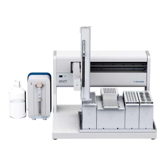
GX-271 Liquid Handler and GX-271 ASPEC™
This document contains instructions for setting up and installing the Z-arm on the GX-271 instruments. For complete
setup instructions, refer to the user's guide included on the documentation CD that is shipped with the instrument.
Warning! All of the components on the Z-arm must be installed before the Z-arm is attached to the instrument. Do not
install the Z-arm until instructed to do so in this document.
The Z-arm and its components should be assembled and installed in the following order:
1
Isolator Probe Holder Installation
2
Guide Foot Installation
3
Fraction Collection Valve Installation (Optional)
a) Low Mount
4
Z-Arm Installation
5
Adjusting the Z Travel Height
6
Probe Installation
7
LLD (Liquid Level Detection) Cable Installation
8
Final Z-Arm Height Adjustment
Technical Specifications
Technical Specification
Arm speed
Vertical punch strength
Phone: 608-836-1551 • Fax: 608-831-4451 • E-mail: sales@gilson.com, service@gilson.com, training@gilson.com • www.gilson.com
©2008 Gilson, Inc. All rights reserved.
Setup Instructions
GX-27X Series Z-Arm
(Part Number 260465)
Definition
125 mm/sec in Z dimension
4.5 kg (10.0 lb)
Gilson, Inc. World Headquarters
3000 Parmenter Street • P.O. Box 620027 • Middleton, WI 53562-0027 USA
Gilson S.A.S. • 19, avenue des Entrepreneurs, BP 145, F-95400 VILLIERS LE BEL France
LT319636-04
Advertisement
Table of Contents

Related Manuals for Gilson GX-27X Series


Summary of Contents for Gilson GX-27X Series
- Page 1 3000 Parmenter Street • P.O. Box 620027 • Middleton, WI 53562-0027 USA Phone: 608-836-1551 • Fax: 608-831-4451 • E-mail: sales@gilson.com, service@gilson.com, training@gilson.com • www.gilson.com Gilson S.A.S. • 19, avenue des Entrepreneurs, BP 145, F-95400 VILLIERS LE BEL France ©2008 Gilson, Inc. All rights reserved.
- Page 2 Isolator Probe Holder Installation Follow the instructions below to install the isolator probe holder (part number 2604615) on the isolator mounting block on the Z-arm. Note: The isolator mounting block is factory-installed. Do not remove it from the Z-arm. Using the 3 mm Allen wrench included in the GX-27X accessory package, remove the screw from the bottom of the isolator mounting block on the Z-arm.
- Page 3 Fraction Collection Valve Installation (Optional) Low Mount The fraction collection valve is installed on the guide foot. To install the fraction collection valve: Place the valve on top of the guide foot as shown in the photo. Align the two holes on the bottom of the valve with the holes on the guide foot.
- Page 4 Adjusting the Z Travel Height The Z travel height is set by default to the S2 position (for 125 mm probes). Follow these steps to adjust the Z travel height: Using the 3 mm Allen wrench included in the accessory package, remove the stop pin (part number 260463) from the Z-arm.
- Page 5 LLD (Liquid Level Detection) Cable strain relief Installation cable To install the liquid level detection cable assembly (part number 260461126): Tighten the hex nut on the front of the isolator probe holder. LLD port Place the metal slot end of the cable over the metal tab on the isolator probe holder.
Need help?
Do you have a question about the GX-27X Series and is the answer not in the manual?
Questions and answers