
Subscribe to Our Youtube Channel
Related Manuals for SPX Radiodetection RD7000+


Summary of Contents for SPX Radiodetection RD7000+
- Page 1 RD7000 ™ Radiodetection’s utility specific cable and pipe locators Operation Manual Issue 1 January 2011 90/RD7K+-OPMAN-ENG/01...
-
Page 3: Important Notices
Preface Before you begin Safety This equipment shall be used by fully qualified and trained Thank you for your interest in Radiodetection’s RD7000+ personnel only. cable and pipe locator. Radiodetection locators detect almost all buried cables The RD7000+ delivers the very latest in cable and pipe and most conductors, but there are some which do not location technology in a powerful yet ergonomic and light- radiate signals and which Radiodetection locators cannot... -
Page 4: Fcc And Industry Canada Statements
Copyright statement respecte la norme CNR-310 d’Industrie Canada. This manual is Copyright © 2010 Radiodetection LTD – SPX Corporation. All rights reserved. Radiodetection LTD is a subsidiary of SPX Corporation. This manual may not be copied, reproduced or sold in whole or in part without expressed written permission by Radiodetection Ltd. -
Page 5: Table Of Contents
Table of contents Preface 3.6.1 Passive frequencies Before you begin 3.6.2 Active frequencies Important notices 3.6.3 Selecting frequencies General 3.7 TruDepth measurement ™ Safety 3.8 SideStepauto ™ Batteries 3.8.1 Using SideStepauto FCC and Industry Canada statements 3.9 Dynamic Overload Protection Training 3.10 StrikeAlert ™... - Page 6 6.2.1 Manhole covers 9.4 Upgrading software 6.2.2 Using lighting columns 9.5 Care and maintenance 6.2.3 Finding a good ground point 9.5.1 General 6.3 Double-ended connections 9.5.2 Batteries and power supply 6.3.1 Making a double-ended connection 9.5.3 Cleaning 9.5.4 Disassembly Section 7 – Using Accessories 9.5.5 Service and maintenance 7.1 About accessories Section 10 –...
-
Page 7: Section 1 - Introduction
Section 1 – Introduction 1.1 About this manual RD7000TL+ and PL+ models and an accessory A-frame. Section 9 provides information on extended warranty, This manual provides cable and pipe survey professionals remote product validation and maintenance advice with comprehensive operating instructions for the RD7000+ locator and transmitter system. -
Page 8: Figure 2.1: Rd7000+ Locator
Figure 2.1: RD7000+ locator Figure 2.2: locator keypad Figure 2.3: locator LCD 2 RD7000+ Operation Manual... -
Page 9: Section 2 - System Overview
Section 2 – System overview 2.1 RD7000+ locator 2.1.1 Locator features Compass: Shows the direction of the located cable relative to the locator. Keypad. Null / Peak icon: Indicates antenna selection. LCD with auto backlight. Sonde icon: Indicates that the signal source is from Speaker. -
Page 10: Figure 2.4 Rd7000+ Transmitter
Figure 2.4 RD7000+ transmitter Figure 2.5: Rechargeable battery pack Figure 2.6: transmitter keypad Figure 2.7 transmitter LCD 4 RD7000+ Operation Manual... -
Page 11: Tx-1, Tx-3 And Tx-10 Transmitters
2.2 Tx-1, Tx-3 and Tx-10 transmitters 2.2.1 Transmitter features Keypad. LCD. Removable accessory tray. Rechargeable battery pack. 2.2.2 Transmitter keypad Power key : Switches the unit on and off. Opens the transmitter menu. Frequency key : Selects frequency. Menu navigation key. Up and down arrows : Adjusts the output signal. -
Page 12: Section 3 - Basic Operation
Section 3 – Basic operation 3.1 Starting the system An optional Lithium Ion rechargeable battery pack is also available for the RD7000+ Tx1, Tx3 and Tx10 The locator and transmitter are battery powered. Install transmitters. good quality D-cell (LR20) NiMH or Alkaline batteries The rechargeable battery packs provide an estimated 8- into the locator and transmitter battery compartments hour working time, depending on use. -
Page 13: Language
3.2.2 Language Press the key to accept your selection and return to the main menu. The locator and transmitter support a number of languages. You can specify your preferred language Press the key to return to the main operation using the menu system. screen. -
Page 14: Navigating The Transmitter Menu
3.3.3 Navigating the transmitter menu WARNING! Wearing headphones may impede First power up the transmitter. your awareness to dangers in the field such as moving traffic or other heavy machinery. Exercise Press the key to enter the menu. caution! Use the arrows to scroll through the menu options. -
Page 15: Selecting Frequencies
For more information on measuring depth, please refer the hazard and guard exposed conductors to prevent accidental contact. to Section 5. 3.6.3 Selecting frequencies 3.8 SideStepauto ™ It is important to select the correct or appropriate frequency SideStepauto allows the transmitter to calculate the for your particular application. -
Page 16: Strikealert
3.10 StrikeAlert 3.12 Backlight ™ StrikeAlert detects shallow pipes or cables and warns The transmitter and locator feature a backlight to improve the operator with an audible alarm and visual display. The LCD visibility when required. The locator’s backlight is alarm is characterized by a rapid warbling sound and a controlled by an ambient light sensor and does not require flashing operating mode indicator. -
Page 17: Transmitter Power Output
3.14 Transmitter power output The transmitter supports several power output modes to help you select the optimal settings for your requirements whilst helping to prolong battery life. 3.14.1 Adjusting power output To adjust the power output: Switch on the transmitter. Press the keys to increase or decrease power output. -
Page 18: Section 4 - Locating Cables And Pipes
Section 4 – Locating cables and pipes This section introduces the principals and techniques of To select null mode: locating buried cable and pipe utilities with the RD7000+ Press and release the key to switch the system. For more information on the theory of cable locator on. -
Page 19: Trace
4.3 Trace Figure 4.2: Pinpointing a target line Line tracing can be accelerated by switching the locator to null response. Move the locator left and right while walking along the path of the line to observe the null directly over the line and a peak response to each side of the line. -
Page 20: Sweep And Search
Switch to null response mode and move the locator to Figure 4.4: Passive sweep find the null position. If the position of the peak and the null pinpoints correspond, it can be assumed that the pinpoint is precise. The pinpoint is not precise if the marks do not correspond, but both marks will show an error to the same side. -
Page 21: Figure 4.5: Inductive Search
Figure 4.5: Inductive search The second person holds the locator at the start of the area to be searched and with the locator antennae at right angles to the probable direction of the buried lines. Set the locator sensitivity level as high as possible without the locator picking up any airborne signals directly from the transmitter. -
Page 22: Section 5 - Depth And Current Readings
Section 5 – Depth and current readings 5.1 Depth readings To avoid signal distortion, do not apply the signal by induction. If direct connection or signal clamping is not The RD7000+ can measure the depth of buried possible, place the transmitter at least 15 meters from the conductors down to depths of approximately 6 meters point of any depth measurements. -
Page 23: Verifying Depth Measurements
5.2 Verifying depth measurements Method 1 Check a suspect or critical depth reading by lifting the Place the transmitter on top of a non-metallic object, such locator 50mm (2 inches) above the ground and repeating as a cardboard box, on the ground and away from any the measurement. -
Page 24: Current Readings
5.3 Current readings Figures 5.4 – 5.6: Taking current readings 5.3.1 Identification using current measurements Measuring current value on a line helps confirm the identity of the line and provides information about the condition of cable insulation or pipe coating. 5.3.2 About current measurements The transmitter applies a signal or current onto a target line. -
Page 25: Applying A Transmitter Signal
5.3.3 Applying a transmitter signal Figure 5.7: Current readings using transmitter signals The transmitter signal can be connected, clamped or induced to the target line in the same way as the signal for line tracing is applied. 5.3.4 Signal current measurements Pinpoint the line and confirm the accuracy of the peak pinpoint with a null pinpoint. -
Page 26: Section 6 - General Locating Tips
Section 6 – General Locating tips 6.1 Eliminating services Figures 6.1 – 6.4: Interference from services 6.1.1 Induction If several conductors are running parallel and it is not possible to connect a transmitter, each line may be located separately. Proceed as follows: Perform a sweep of the area to find the position and number of conductors in the area. -
Page 27: Signal Grounding
• Avoid applying the signal by induction. The signal may If the lighting column is made from concrete make the be coupling to more than one line directly from the transmitter connection to the cable sheath unless the transmitter. Use the signal clamp where possible. cable is earthed to the inspection doorframe. -
Page 28: Double-Ended Connections
6.3 Double-ended connections Figure 6.5: Making double-ended connections Large diameter water pipes and gas distribution pipes that are laid in sections sometimes have insulated joints between the sections and can be difficult to locate using a single ended connect. This is because when using a single ended connection ground return, signals can often cause confusion by returning to the transmitter along other lines. -
Page 29: Section 7 – Using Accessories
Section 7 – Using Accessories 7.1 About accessories 7.2.2 Connecting a clamp Put the clamp connector into the accessory socket Both the transmitter and locator are compatible with on the front of the RD7000+ locator. a wide range of accessories, including the relevant RD7000/RD8000/RD4000 accessories. -
Page 30: Available Locator Clamps
7.2.3 Available locator clamps 7.3.1 Connecting the clamp Plug the clamp into the transmitter output socket. Standard clamp Put the clamp around the pipe or cable and ensure that The clamp plugs into the locator accessory socket and is the jaws are closed. Switch the transmitter on. used for cable identification at points where the cable can The line should be grounded (earthed) on each side of the be accessed. -
Page 31: Available Transmitter Clamps
7.3.2 Available transmitter clamps 7.4.2 Choosing a suitable sonde Although transmitter and locator clamps look the same, Check that the sonde has sufficient range for the they have different internal windings. To prevent the wrong application and is dimensionally small enough and clamp being connected, transmitters and locator clamps sufficiently robust for the application. -
Page 32: Locating And Tracing A Sonde
7.4.5 Locating and tracing a sonde Figure 7.6: Sonde deployment Insert the sonde in the drain or duct access and locate it while it is still just in view at the drain or duct entrance. Hold the locator vertical directly over the sonde with the antenna in line with the sonde. -
Page 33: Checking Sonde Depth
7.4.6 Checking sonde depth Sewer sonde The RD7000+ locator will automatically display the depth This sonde incorporates a very strong housing and makes of a located sonde providing the locator is correctly the sonde suitable for use in municipal sewer systems. oriented and positioned above the sonde. -
Page 34: Stethoscopes
7.5 Stethoscopes 7.6 Submersible antenna 7.5.1 When to use a stethoscope 7.6.1 When to use a submersible antenna At times, it may not be possible to put a locator clamp around a cable because of congestion or because of Tracing buried pipes and cables across waterways and inaccessibility. -
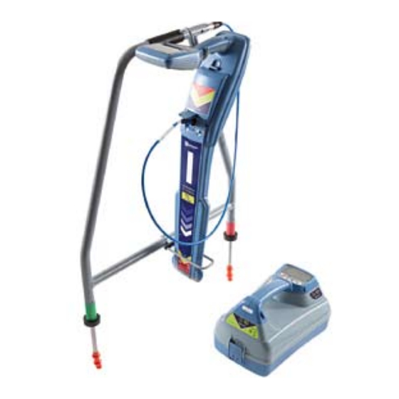
Page 35: Figure 7.13: Using A Submersible Antenna
Tips for using a submersible antenna The user in the boat should be a specialist or have considerable experience using a locator so that they can give concise instructions to the diver. It is prudent for the pair to practice working together on dry land before attempting to locate underwater. -
Page 36: Section 8 – Fault-Finding
Section 8 – Fault-Finding 8.1 About fault-finding Before taking the reference reading set up the transmitter and locator as follows: The RD7000TL+ and RD7000PL+ models are capable of locating cable to ground faults caused by damaged cable On the transmitter: sheaths. -
Page 37: Figure 8.1: Cable Sheath Fault-Finding
Take readings at the survey intervals determined by the NOTE. To establish how often to take readings on the cable, move away from the ground stake and take reference reading. To locate the cable during a Fault-Find further readings until the arrow has difficulty in locking survey, press the key once and the locator will switch and the dB reading is low. -
Page 38: And Maintenance
Section 9 – Extended Warranty, eCAL and Maintenance ™ 9.1 Product Registration and Go to: www.radiodetection.com/centrosmanager. Extended Warranty Click on the link to download Centros Manager and a File Download Window will appear. You will have a Your RD7000+ locator and transmitter are supplied choice of either, Run or Save. -
Page 39: Upgrading Software
To validate your RD7000+, you must first carry out the Register your RD7000+ locator by going to: following: www.radiodetection.com/extendedwarranty. See section 9.1 for more details. • Register your RD7000+ locator at: Download Centros Manager by going to: www.radiodetection.com/extendedwarranty. See section 9.4 for more details. www.radiodetection.com/centrosmanager. -
Page 40: Care And Maintenance
9.5 Care and maintenance 9.5.4 Disassembly Do not attempt to disassemble this equipment under any The RD7000+ locator and transmitter is robust, durable circumstances. The locator and transmitter contain no and weatherproof. However you can extend your user serviceable parts. equipment’s life by following these care and maintenance guidelines. -
Page 41: Section 10 – Appendices
Section 10 – Appendices 10.1 Specifications for the locator and transmitter Sensitivity 6E-15Tesla, 5µA at 1 meter (33kHz) Dynamic range 140dB rms /√Hz Selectivity 120dB/Hz Depth accuracy Line: ± 5% tolerance 0.1m (4") to 3m (10ft) Sonde: ±5% tolerance 0.1m (4") to 7m (23ft) Maximum Depth* Line 6m (20ft), Sonde 15m (50ft) Fault-Finding (FF) -
Page 42: Supported Accessories
10.3 Supported accessories Description Part Number Transmitter Accessories UK Plug Connector 10/AC1231-4KTX-LPC-UK Euro Plug Connector 10/AC1231-4KTX-LPC-EUR Live Cable Connector 10/AC1231-4KTX-LCC 2" (50mm) Transmitter Clamp 10/TC2136-4KTX 4" (100mm) Transmitter Clamp 10/TC1769-4KTX Earth Reel 09/310-4KTX Mains power AC transformer to 12V DC New 10/RD7K8KUMPSU Tx Direct Connection Lead 17/TX2609E1... - Page 43 Description Part Number Sondes and accessories Standard Sonde 33kHz Depth 5m 10/SC0412-33R Sewer Sonde 33kHz Depth 8m 10/SA0337-33R Super Sonde 33kHz Depth 15m 10/SB0338-33R Slim Sonde 33kHz Depth 3.5m 10/SD0322-33R Slim Sonde Plain End Cap 10/SD0223 Slim Sonde Blank End Cap 10/SD0268 S18A Sonde 33kHz 10/S18/82-33-000...
- Page 44 Copyright 2011 Radiodetection Ltd - SPX Corporation. All rights reserved. Radiodetection is a subsidiary of SPX Corporation. SPX and Radiodetection are trademarks of Radiodetection Ltd. and SPX Corporation. Due to a policy of continued development, we reserve the right to alter or amend any published specification without notice. This document may not be copied, reproduced,...
Need help?
Do you have a question about the Radiodetection RD7000+ and is the answer not in the manual?
Questions and answers