
Subscribe to Our Youtube Channel
Related Manuals for Dini Argeo 3590EGT Series


Summary of Contents for Dini Argeo 3590EGT Series
-
Page 1: User Manual
Indicators series 3590EGT EGTCHECK_05_15.08_IT_U USER MANUAL WEIGHT INDICATOR EGTCHECK: DINAMIC OR STATIC WEIGHT CONTROL ON TAPE Indicators series 3590EGT... -
Page 2: Table Of Contents
3590EGTCHECK_05_15.08_IT_U INDEX INTRODUCTION ............................5 TECHNICAL SPECIFICATIONS ........................7 INSTALLATION ............................8 Case and dimensions ........................8 Connectors............................9 Power supply ........................... 9 Start up ............................10 Turning off the instrument ......................10 INDICATOR PARTS ............................ 11 display ............................12 4.1.1 Display indicators ...................... - Page 3 SYSTEM STATUS CONTROL ......................25 ENABLING/DISABLING THE WEIGHIG CYCLE ................. 25 DESCRIPTION OF THE CYCLE PHASES..................... 26 WEIGHT ACQUISITION ........................26 7.4.1 AT HALF WITH A SENSOR ....................26 DESCRIPTION OF THE SYSTEM ....................... 26 7.5.1 IN MOTION WITH 1 PHOTO CELL ..................28 7.5.2 IN MOTION WITH 2 PHOTO CELLS ..................
- Page 4 7.21 ALARM OUTPUT MANAGEMENT ....................45 Printouts ..............................46 Error Messages ............................47 10 Progressives ............................. 48 10.1 Additional value ..........................48 10.2 Progressive digits ........................... 48 10.3 Ticket Progressive .......................... 48 10.4 Lot Progressive ..........................48...
-
Page 5: Introduction
INTRODUCTION INTRODUCTION This manual was created to help you install and learn all about the functional possibilities of the purchased indicator. The instrument is suitable for use in various weighing environments. Not only does it have all the normal features of high-precision scales, but it also gives you the possibility to work in specific environments due to the functioning modes contained in the software implemented in the FLASH MEMORY on the internal board. - Page 6 INTRODUCTION Do not install in any area where there is a risk of explosion. The crossed-out wheeled bin on the product means that at the product end of life, it must be taken to separate collection or to the reseller when a new equivalent type of equipment is purchased.
-
Page 7: Technical Specifications
TECHNICAL SPECIFICATIONS TECHNICAL SPECIFICATIONS 12 Vdc ( 8 ÷ 24 Vdc in the IO versions), with internal 100 ÷ 240 Vac POWER SUPPLY (50÷60 Hz) / 12 Vdc adapter. From -10 to +40 °C. OPERATING TEMPERATURE 24 bit Sigma Delta. CONVERTER Only in gross mode, programmable at +/- ¼, ½, 1, 2 divisions. -
Page 8: Installation
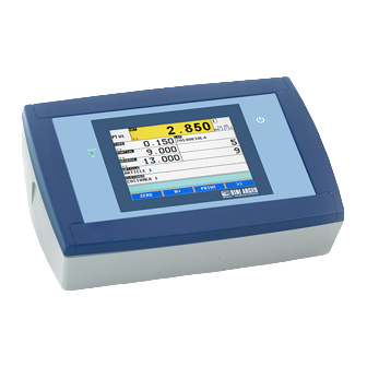
INSTALLATION INSTALLATION Case and dimensions The indicator has a STAINLESS STEEL case, whose external dimensions are shown in the Figure 1. It can be simply put on a table or fixed to a shelf or column available on request. NOTE: If the identification plate is supplied separately (therefore not attached to the indicator), it isadvisable to attach it to the indicator, in order to be able to identify the instrument. -
Page 9: Connectors
INSTALLATION Connectors Part Description RJ45 connector Fixing for shelf or column mounting Available for load cells / serial lines / inputs / outputs Power supplì input Power supply The indicator is powered with 12Vdc voltage (8 ÷ 36 Vdc in the IO version), through an internal adapter which converts the 100 ÷... -
Page 10: Start Up
INSTALLATION Start up Step Description Screen Press the key until the instrument poker on. Il logo ( Logo to show at the start up) and the software version appear for some instants. EGT-CHECK-XX is the name of the installed software, in which XX identifies the language. -
Page 11: Indicator Parts
INDICATOR PARTS INDICATOR PARTS Part Description Touch screen Power button... -
Page 12: Display
INDICATOR PARTS display The indicator presents 2 main screens, Figure 1 and Figure Figure 1. First main screen Figure 2. Second main screen... - Page 13 INDICATOR PARTS Element Description Display indicators Active scale Touch to switch to the next scale Time and date Touch to change the date Weight/Volume value on the active scale Touch to tare the gross weight Tare value Touch to insert a preset tare Description of the first input text (OPERATOR) Touch to change the description of the first input text Touch to select the lot...
-
Page 14: Display Indicators
INDICATOR PARTS 4.1.1 Display indicators Symbol Description Il peso rilevato dal sistema di pesatura si trova in prossimità dello zero, compreso nell’intervallo –1/4 +1/4 della divisione della bilancia The weight in unstable A tare value has been acquired A preset tare value has been entered Active weighing range Locked keybord Transmission of the data to the printed serial port... -
Page 15: Main Functioning Description
MAIN FUNCTIONING DESCRIPTION MAIN FUNCTIONING DESCRIPTION All the functions of the indicator are available from the button in the second screen. The functions are divided into the following groups: Group Description Scale functions Operations to the weight (zeroing, tare,…) Printout Print functions management Generic operations to the indicator (Lock keyboard, Generic functinos... -
Page 16: Tare
MAIN FUNCTIONING DESCRIPTION If the weight on the scale is included in the percentage ( Zeroing percentage with ZERO key), it is zeroed and the >0< indicator turns on. Tare 5.2.1 Semiautomatic tare Step Description Screen Touch on the weight area to tare the gross weight on the scale. -
Page 17: Preset Tare
MAIN FUNCTIONING DESCRIPTION 5.2.2 Preset tare Passo Descrizione Schermata Touch on the tare area Insert the preset tare value and confirm with the OK key The entered value is subtracted from the gross weight and the PT indicator turns on 5.2.3 Link a preset tare to an article It’s possible to insert the tare calue o fan article in the database. -
Page 18: Input Texts
MAIN FUNCTIONING DESCRIPTION Input texts Step Description Screen Touch on the button TEXTS to get acces to the input texts. Touch on the lot text to be changed. Insert the content f the text and confirm with the OK button Tounch on the ESC button to go backto the main screen. -
Page 19: Databases
MAIN FUNCTIONING DESCRIPTION Databases 5.4.1 Insertion Step Description Screen Touch on the ARTICLES button to get access to the destre database. Select the destre position by touching element touching the NEW button to insert an element in the first empty position. -
Page 20: Modification
MAIN FUNCTIONING DESCRIPTION Il The inserted element appears in the table with the first field value 5.4.2 Modification Step Description Screen Touch the button to get access to the destre database. Touch the element or the A..Z button to search the element to be updated. -
Page 21: Cancellation
MAIN FUNCTIONING DESCRIPTION Repeat the operation for the destre fields to be updated and press the button to confirm. 5.4.3 Cancellation Step Description Screen Touch the button to get access to the destre database. Touch the element or the A..Z button to search the element to be deleted. -
Page 22: Alphanumeric Search
MAIN FUNCTIONING DESCRIPTION The element has been removed from the database. 5.4.4 Alphanumeric search Step Description Screen Touch the A..Z button in the database update/selection screen. Insert the first characters of the element to search. The table shows all the elements starting with the typed characters. -
Page 23: Search By Element Index
MAIN FUNCTIONING DESCRIPTION 5.4.5 Search by element index Step Description Screen Touch the INDEX button in the database update/selection screen Insert the index of the destre element and confirm. In selection the element s selected and the main screen is displayed. In update the element fields are displayed and can be modified. -
Page 24: System Status
SYSTEM STATUS SYSTEM STATUS The following are the statuses displayed on the display, the display of the SYSTEM STATUS. To select this view, refer to the previous paragraph. STATE DESCRIPTION ALARM ENGINE Weighing cycle blocked: the entry of EMERGENCY / MOTOR (IN.6) is active for a minimum time set in its step. -
Page 25: Weighing Procedure
WEIGHING PROCEDURE WEIGHING PROCEDURE The programme has been made to manage an automatic weighing cycle on belt, either static or dynamic, with tolerance control, accumulation, and printing of the executed weighs. The input/output allows for the automatic belt management for the handling, weighing, and selection or expulsion. -
Page 26: Description Of The Cycle Phases
WEIGHING PROCEDURE To disabile the weighing cycle one should disable the consensus from downstream (remove the running) for a time greater than the one configured in the relative step: the weighing cycle is interrupted. With the consensus from downstream exclude one, the weighing cycle is always activel. To reenable the weighing cycle one should: a) Enable the consensus from downstream (IN 1 = 0Vdc), se if not excluded in the relative step. - Page 27 WEIGHING PROCEDURE EXAMPLE: START STOP MENU ì ENTER 1 WEIGH START PHOTO CELL 2 WEIGHING BELT 3 PLATFORM 4 CADENCE PHOTO CELL 5 CADENCE BELT 6 EXPELLER BELT 7 WEIGHT INDICATOR The cadence belt supplies the packs to the weighing belt with the possibility of managing their flow, as described in section “MANAGEMENT OF CADENCE PHOTOCELL AND BELT”.
-
Page 28: In Motion With 1 Photo Cell
WEIGHING PROCEDURE 5) Continues with the subsequent cycle phases (proceed in the reading of the following sections) 6) Is ready to carry out a new weigh. It’s possible to set a minimum duration of the stability condition (relative step, RIF.MAN.CHECK (Stab. -
Page 29: In Motion With 2 Photo Cells
WEIGHING PROCEDURE 7.5.2 IN MOTION WITH 2 PHOTO CELLS The weight acquisition takes place in the same way as the previous mode, but the use of a second photo cell allows to take advantage of all the possible weighing time depending on the pack that is to be weighed. -
Page 30: In Motion Withot Photo Cells
WEIGHING PROCEDURE 7.5.3 IN MOTION WITHOT PHOTO CELLS The positioning and the weight acquisition takes place with the weighing system in motion. This uses the rising edge of the weight to start the acquisition of the weighing and the falling edge for the reactivation of the weighing. -
Page 31: Tolerance Check
WEIGHING PROCEDURE b) Starts acquire a set of weighs. c) Waits foro ne of the fine weigh conditions to take place, in other words: 1) The weight is stable, weight variation is in the range set in the configuration, RIF.MAN.CHECK; 2) Ends the weight time, RIF.MAN.CHECK (Time For Weigh Calculation);... -
Page 32: Checking With Article And T1, T2, T3 Tolerance Setting
WEIGHING PROCEDURE Evacuation Automatic ejection (if set) For operational details read the next sections. The tolerance check interval may be set in 3 ways, as descrive in the next paragraphs and set in the step (Tolerance Check). In the following paragraphs the tolerance check range setting is described, as well as the functions related to the tolerance checking. -
Page 33: Checking With Article And Minimum And Maximum Threshold Setting
WEIGHING PROCEDURE 7.6.2 CHECKING WITH ARTICLE AND MINIMUM AND MAXIMUM THRESHOLD SETTING The tolerance range is assigned by setting in the article the minimum and the maximum weight thresholds. The range is assigned as follows: - by setting both the thresholds, the weight is within tolerance if its value is within the 2 thresholds - by setting the minimum threshold only (maximum threshold equal to zero), the weight is within tolerance if its value is between the minimum threshold and the full scale capacity. -
Page 34: Checking Quantities In Ml
WEIGHING PROCEDURE In the tecnica setup (RIF.MAN.CHECK ), one can set the tlerance range limits. Below is an example in programming the combinations for obtaining the tolerance range shown in the figure. The weight is valid only if it’s between TARGET - T2 and TARGET + T3. : tolerance range WEIGHT <... -
Page 35: Automatic Target Recalculation After N Weights Within Tolerance
WEIGHING PROCEDURE !! IMPORTANT !! In order to weigh in ml, calibrate the instrument in grams and set the database unit of measure in grams. The target of the article is directly taken into consideration in ml as well as the relative tolerances. -
Page 36: Mandatory Correction Of The Weight
WEIGHING PROCEDURE NOTE: Once the RESTART impulse is given, the instrument re-enables the weighing belt (OUT2), without checking if the manual expulsion of the out of tolerance weigh is carried out, and executes in any case, the automatic expulsion. MANDATORY CORRECTION OF THE WEIGHT The operator MUST correct the weight before the restart of the belt, by adding or removing material in order to have the weight within the tolerances. -
Page 37: Weight Result Indication And Enabling Of The Linked Outputs
WEIGHING PROCEDURE 7.10 WEIGHT RESULT INDICATION AND ENABLING OF THE LINKED OUTPUTS Dopo la procedura di totalizzazione è possibile visualizzare sul display, per un tempo impostabile nel passo relativo (RIF.MAN.CHEK (Weight Visualization Duration), il peso totalizzato (nella casella del peso) e un messaggio che indica l’esito della pesata con l’eventuale numero di pesata se il peso è... -
Page 38: Outputs Managed In The Functioning With Article And Tolerance
WEIGHING PROCEDURE The instrument has furthermore 7 tolerance outputs, in order to command, for example, an external traffic light, or a sorter. After the totalization procedure, the output corresponding to the tolerance level in which the weight is detected, is activated; the activation time of the output is configurable In case of belt stop (see section “STOP AND RESTART OF THE BELTS”) the activation time is frozen, and the output remains active;... -
Page 39: Stop And Restart Of The Belts
WEIGHING PROCEDURE MANAGED OUTPUT IN THE FUNCTIONING WITH OR WITHOUT ARTICLE AND SETTING OF THE MINIMUM AND MAXIMUM THRESHOLDS The following outputs are managed to obtain 3 tolerance levels: weight under minimum threshold (OUT8), weight in tolerance (OUT5), weight over maximum threshold (OUT9). The entry of the thresholds is carried out during the article insertion or directly in the weighing phase (see section “TOLERANCE CHECK”). -
Page 40: Stop Of Belts After A Number Of Weights Out Of Tolerance
WEIGHING PROCEDURE 7.12.3 STOP OF BELTS AFTER A NUMBER OF WEIGHTS OUT OF TOLERANCE This function stops automatically the weighing belt when a number of consecutive out of tolerance weighs set in the relative step (RIF.MAN.CHEK (Weights Out Of Tol. To Stop Belt). By setting the 0 value, the function is disabled. - Page 41 WEIGHING PROCEDURE - if one sets the 1 value, at the end of each weigh the instrument waits for the evacuation time set in the relative step (RIF.MAN.CHECK (Evacuation Time)) and executes the autozero function if a) the belt is empty (instrument in “PACK WAIT” status, no pack on the belt or in “POSITIONING”) b) the weight is different from 0 (belt out of zero) if one sets the n (>1) value, the instrument executes the autozero function after having...
-
Page 42: Cycle And Interrupt Of The Weigh (Not Weighed Pack)
WEIGHING PROCEDURE With automatic zero at time or at the re-enabling of the weighing cycle, the system goes into alarm condition, the display shows the “AUTOZERO FAILED” message and a RESTART impulse is required to restart. Once the RESTART impulse is given, the automatic zero enter into function. With automatic zero at weighs, the system doesn’t go into alarm condition and allows the pack to continue. -
Page 43: Downstream Block
WEIGHING PROCEDURE 7.16 DOWNSTREAM BLOCK The system can handle the automatic disabling of the cycle from the downstream of the belt, when in the belt downstream lock condition due to processing or error. If it is not possible to manage the disabling of the cycle at the end of the weigh, in order to avoid the cancellation of the weigh in progress, it can be useful to set a delay time of the downstream lock: the instrument waits for the set time period to pass before disabling the cycle;... -
Page 44: Management Of Cadence Photocell And Belt
WEIGHING PROCEDURE if the acquisition is terminated 1) the “WEIGHED PACK” message appears depending on the selected visualization (see section “MODIFICATION OF THE DISPLAYED DATA”); 2) a RESTART impulse is required to restart: the operator must remove manually the weight. 3) Once the RESTART impulse is given, the instrument executes the autozero at start-up, as described in section “POWER SUPPLY &... -
Page 45: Alarm Output Management
WEIGHING PROCEDURE 7.21 ALARM OUTPUT MANAGEMENT There are 6 cases witch determine the conditions for the alarm activation: Weight out of tolerance (only if the manual expulsion has been selected), with relative step enabled. The number of weights out of tolerance has reached the value set in the relative step. Weight unstable for a time greater than the value set in the relative step (only if the weighing at halt is selected) . -
Page 46: Printouts
Printouts Printouts The indicator has 13 print functions, each function has an associated format. When a function has been put into execution through the operation illustrated in the scheme, the associated format is sent to the print serial port. There are 30 available formats to associate to the print functions. To change the format of the print function use MENU ... -
Page 47: Error Messages
Error Messages Error Messages The net weight is below the Place a piece on the minimum weight allowed scale with a weight greater than the (20 divisions with approved minimum acceptable. instrument, zero with non Wait until the weight approved instrument). -
Page 48: Progressives
Progressives Progressives 10.1 Additional value In MENU Progressives Additional value it’s possible to set a value of up to 6 digits, which is summed to each totalisation, and can be recalled in the printing. The same value is linked independently to three total types (PARTIAL, GENERAL, and GRAND TOTAL), in other words, it is possible to print three different values which will be cleared with the clearing of the relative total. -
Page 49: Declaration Of Conformity
Indicatori serie 3590EGT EGTCHECK_05_15.08_IT_U DECLARATION OF CONFORMITY This device conforms to the essential standards and norms relative to the applicable European regulations. The Declaration of conformity is available in the web site www.diniargeo.com. WARRANTY The TWO-YEAR warranty period begins on the day the instrument is delivered. It includes spare parts and labour for repairs at no charge if the INSTRUMENTS ARE RETURNED prepaid to the DEALER’S PLACE OF BUSINESS.
Need help?
Do you have a question about the 3590EGT Series and is the answer not in the manual?
Questions and answers