
Related Manuals for Dini Argeo DFWATEX2GD


Summary of Contents for Dini Argeo DFWATEX2GD
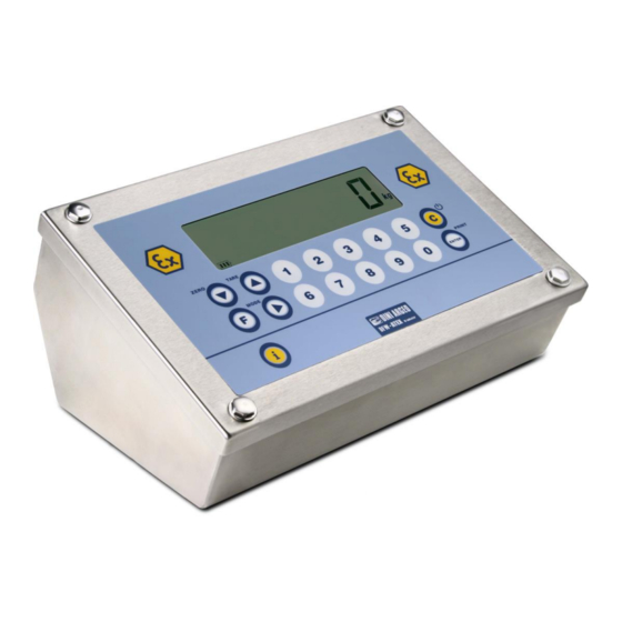
- Page 1 TECHNICAL MANUAL WEIGHT INDICATOR DFWATEX2GD, DFWATEX2GDIO, DFWATEX2GDM, DFWATEX2GDMI DFWATEX2GD_05.03_12.09_EN_T 1 of 49...
-
Page 2: Table Of Contents
10 CONNECTION SCHEMES .............................. 49 10.1 EXPLANATION OF EXPANSION BOARDS (PRESENT DEPENDING ON THE MODEL) ........49 For the simplest usage in this manual, the name DFWATEX stands for both DFWATEX2GD, DFWATEX2GDIO, DFWATEX2GDM and DFWATEX2GDMI, so where “DFWATEX” is used it is understood as “DFWATEX2GD, DFWATEX2GDIO, DFWATEX2GDM and DFWATEX2GDMI”. -
Page 3: Warnings
These warnings apply to DFWATEX2GDxxx weight indicators and to the optional ATEX version JB4Q junction box ESSENTIAL PREREQUISITE ALONG WITH THIS TECHNICAL MANUAL ONE SHOULD ALSO READ AND UNDERSTAND THE CORRESPONDING DFWATEX2GD USER MANUAL IN WHICH IMPORTANT WARNINGS ARE INDICATED DFWATEX2GDxxx 3 of 49... -
Page 4: Requirements For An Effective Installation
2 REQUIREMENTS FOR AN EFFECTIVE INSTALLATION To obtain the best results it is recommended to install the indicator and the platform (or transducer) in a place with the following conditions: A flat and level resting surface Stable and vibration free No dusts and aggressive vapours No draughts Make sure the platform is level or that the loading cells are resting evenly... -
Page 5: Setup Environment
4 SETUP ENVIRONMENT With "SETUP ENVIRONMENT" we intend a specific menu, where it’s possible to set all the functioning parameters of the indicator. To enter it, turn on the instrument and, while the firmware version is being displayed, press the TARE key for an instant. - Page 6 Allows to enter a step or confirm a parameter inside a step. Allows to exit a step without confirming the possibly modified parameter and go to the preceding level. When entering a numeric value it quickly zeros the displayed value. Allow to enter numeric values, from right to left.
-
Page 7: Set-Up Environment Block Diagram
4.1 SET-UP ENVIRONMENT BLOCK DIAGRAM The following diagram shows the structure of the indicator’s set-up environment; each step has been described in detail in the “DESCRIPTION OF THE STEPS” section. MAStr (§) rEPE (§) (!) ntGS StPG tYPE (§) (!) Ind.Ch, dEP.Ch StPn inout (!) G. - Page 8 DFWATEX2GDxxx 8 of 49...
-
Page 9: Description Of The Steps
ConFiG (§) VCEL Min, (!) MAX nChan (*)(§) (!) Ch2 ... Ch4 (!) FLt 3, FLt 0..3, doS.0..3, Param. Stabil. h.r.0..7, dyn.0..3, SLW.0..3, hoLd 0...5, r.AdC 0...1, r.AdC d, r.AdC S Auto-0 (*) (!) EnAb, diSAb 0trACk (*) (!) ½, ¼, 1, 2, no diV.Stb. - Page 10 F.ModE SCALE FUNCTIONING FunCt FUNCTIONING MODE MAStr (M) Multiscale Repeater rEPE (M) Single scale repeater Std (S) Kg / lb conversion. ntGS (S) Net weight / gross weight conversion. StPG (S) Set point on gross weight StPn (S) Set point on net weight Inout (S) Input / output weigh.
- Page 11 rEACt REENABLING OF THE PRINTOUTS AND THE INDICATOR FUNCTIONS (§) While using the indicator, it is possible to incur in the “no.0.unS” error shown on the display; this means that the printout or the function which one wants to carry out must be renabled (in order to avoid accidental executions). It is possible to set the reenabling in the following modes: “passage of the net weight by zero”, “weigh instability”...
- Page 12 SEtuP SCALE CONFIGURATION ConFiG METRIC CONFIGURATION (*) nChAn SELECTION OF NR. OF INDICATOR CHANNELS (§) 2÷4 in SCALE WITH DEPENDENT CHANNELS functioning mode (“DEP.CH”) (!) 2 (*) With approved instrument the parameter is read-only. (§)The parameter is not displayed if the firmware is MASTER type. If the firmware is STANDARD type, the parameter is not displayed in case of DEPENDENT CHANNELS functioning mode, tyPE parameter.
- Page 13 (!) tr. ½ (*) With approved instrument it is possible to select just the tr. no, tr. ½, tr. ¼ parameters. . (*)diV.Stb DIVISIONS BY STABILITY In this step one enters the number of divisions by which the instrument detects the weight stability; the higher the number of divisions, less is the sensitivity, and consequently the stability is more easily detected.
- Page 14 PrPC.St transmission of the standard string upon the pressing of the ENTER/PRINT key. PrPC.EX transmission of the extended string upon the pressing of the ENTER/PRINT key. NOTE: The transmission of the standard or extended string upon the pressing of the PRINT key is confirmed by “trAnSM”...
- Page 15 CoM.PC PC SERIAL LINE PCModE TRASMISSION ON THE PC SERIAL LINE ondE transmission on external command PC). rEPE.4 transmission to 4-digit remote display. rEPE.6 transmission to 6-digit remote display. Prin.St. transmission of standard string when the ENTER/PRINT key is pressed. Prin.EX transmission of extended string when the ENTER/PRINT key is pressed.
- Page 16 WEi.LEn LENGTH OF THE WEIGHT DATA STRING In this step one enters the number of digits (from 1 to 39) which make up the weight value, including the sign and the non significant digits. For example, if the transmitted string is hh,kk,pppppppp,uu + CR + LF (see the section “TRANSMISSION PROTOCOLS”...
- Page 17 bAud SET BAUD RATE By pressing the ENTER/PRINT key one accesses the selection of the data transmission speed (measured in Baud = bit/second). The possible values are: 1200, 2400, 4800, 9600, 19200, 38400, 57600, 115200. (!) 9600 bit SET PARITY WORD, STOP BIT By pressing the ENTER/PRINT key one accesses the selection of the available values: n-8-1, n-8-2, n-7-2, E-7-1, E-7-2.
- Page 18 (§) The parameter is not displayed if the firmware is MASTER type. inPutS CONFIGURATION OF INPUTS (§) Through this step one sets the function to be linked to each input (optional, up to 4). inP.01 INPUT 1 function nonE Disabled ZEro ZERO key tArE...
- Page 19 Through this step one can initialize the instrument with the subsequent activation of the default parameters. By pressing ENTER/PRINT, a confirmation message (“dFLt?) will appear: confirm again with ENTER/PRINT or exit with any other key. NOTE: The initialization of the instrument causes a cancellation of the present calibration and the activation of the default parameters.
- Page 20 outPut TEST OF THE I/O EXPANSION BOARD RELAYS (OPTIONAL) (§) By pressing ENTER/PRINT the instrument displays “rEL01” and enables relay 1 of the expansion board; press the ZERO or TARE key to enable the other relays of the connected expansion boards. (§) The parameter is not displayed if the firmware is MASTER type.
-
Page 21: Calibration
5 CALIBRATION There are two possible types of calibration, depending on the type of application chosen for the instrument: the “IND.CH.” type (independent channels) and the “DEP.CH.” type (dependent channels, which can eventually be digitally equalized). ConFiG (§) VCEL (!) Min, MAX (!) 1 MhZ, 2 MhZ, 4 MhZ, 8 MhZ, 16 MhZ nChan (*)(§) (!) Ch2 ... -
Page 22: Scale Connected To A Single Channel
5.1 SCALE CONNECTED TO A SINGLE CHANNEL Premise: this procedure is to be followed if one needs to calibrate a single-cell scale, or a scale with various cells equalized externally using a junction box; the scale is connected to a single channel on the board. 1) Enter the SET-UP environment of the scale (when turned on, press the TARE key for an instant while the firmware version is displayed). -
Page 23: If The Zone Of Use Is Different Than The Calibration Zone One Should
1) Enter in the SET-UP ENVIRONMENT of the indicator (when turned on, press for an instant the TARE key while the firmware version is displayed). 2) Nr. of connected Cells Select the number of cells (in other words, the number of channels, from 2 to 4) connected to the indicator SEtuP >>... -
Page 24: Quick Calibration Of Zero
With an APPROVED instrument, when turned on, the value of the zone of use or the gravitational acceleration value is displayed. 5.4 QUICK CALIBRATION OF ZERO It is useful to calibrate just the point of ZERO when a permanent tare weight is put onto the platform (for example a roller unit). -
Page 25: Display Of The Gravity Acceleration And Correction Of The Weighing Error Due To The Different Gravity Acceleration Between Calibration Zone And Utilisation Zone
6 DISPLAY OF THE GRAVITY ACCELERATION AND CORRECTION OF THE WEIGHING ERROR due to the different gravity acceleration between calibration zone and utilisation zone. This instrument conforms to the laws currently in force regarding non-automatic weighing instruments. Such g-sensitive instruments are influenced by the gravitational acceleration value “g” value of the utilization zone, hence it is compulsory to indicate, with a label or on the display, the value of “g”... - Page 26 with the Baud rate at 57600 one can arrive at 16. The transmission works with weight <, =, > 0 with approved or unapproved instrument. NOTE: This protocol is active also in the other functioning modes, only on the PC serial output. - 4 –...
- Page 27 - Reenabling the transmission depends on how the “rEACt” step has been set in the SET-UP environment (passage by zero of the NET weight or instability of the NET weight of 10 divisions; by choosing “always” it works upon instability). For approved instruments: - The transmission takes place if the weight is stable and the net weight is >...
-
Page 28: Prn Port
7.2.2 PRN PORT Please find below the various selectable serial weight transmission modes of the PRN serial port through the corresponding “Pr.ModE” step of the SET-UP environment. TRANSMISSION TO PRINTER (“tPr” and “LP542P” parameters): requests the use of the print key on the indicator (prints upon request of the operator). - Page 29 [CC]MVOL<CR LF> Instrument response: STANDARD STRING (see 7.4 section). Reading command of converter points relative to the weight [CC]RAZF<CR LF> Instrument response in “IND.CH.” mode: STANDARD STRING (see 7.4 section). Instrument response in “DEP.CH.” mode: see the response of the RAZM command. Tare command [CC]TARE<CR LF>...
- Page 30 [CC] INSTRUMENT CODE IN THE FORMAT OF TWO ASCII DECIMAL DIGITS ONLY IF THE 485 PROTOCOL HAS BEEN SELECTED (FOR EXAMPLE 00) For each set channel: Value in converter points relative to the weight Comma character pppppppppp 10 digits which identify the converter points relative to the channel. Comma character Unit of measure "vv"...
- Page 31 should use the saving command (CMDSAVE). If the “KKKKKK” tolerance is not transmitted, the “ZZZZZZ” tolerance is considered as both the lower one as well as the upper one. Print Command [CC]PRNT<CR LF> or [CC]P <CR LF> (short command). Instrument response: [CC]OK<CR LF>...
- Page 32 System response: [CC]OK<CR LF>. For example, to set a APW of 1.55 g, the command is the SPMU1.55<CR LF> or SPMU0001.550 <CR LF> and all the various combinations adding zeros to the right or to the left but taking into consideration that the maximum length of the APW field is 8 characters.
- Page 33 Key disabling command [CC]KEYEt<CR LF> t E to enable the keys t D to disable the keys Response: [CC]OK<CR LF> Status command of the keys [CC]KEYE<CR LF> Response: [CC]KEYEE<CR LF> if the keyboard is enabled [CC]KEYED<CR LF> if the keyboard is disabled Scale information reading: [CC]RALL<CR LF>...
-
Page 34: Transmission Protocols
Reading of the board information: [CC]BOARD<CRLF> Instrument’s answer: [CC]LOADER: aaa, BOARD ID: bbb, BOARD REV: ccc, HWCFG: ddd, SN: xxx, BOARD NAME: nnn<CRLF> In which: loader version in hex form (e.i. 203 for loader 2.03) board ID (numeric value) board revision (numeric value) hardware config. -
Page 35: Extended String
Gross Weight Gross weight with sensitivity times 10 Value in microvolts relative to the weight Value in converter points relative to the weight Comma character pppppppp 8 digits (including any sign and decimal point) which identify the weight. The insignificant digits are filled with spaces. -
Page 36: Master Mode Strings
7.4.3 MASTER MODE STRINGS STANDARD STRING Standard string transmitted on the print port when PR.MODE= ALL.STD or PRPC.ST: SS,KK,WWWWWWWW,UU<CR LF> in which: SS: status: non valid weight (the following data is not valid) in SUM mode this happens when: one or more slaves are not connected one or more slaves are in under/over load condition in single slave mode this happens when the slave is not connected ST: stable data... - Page 37 Select the “Pr.ConF” step and press ENTER/PRINT: one enters the PROGRAMMING MENU OF THE PRINTOUTS. If the system consists of two or more SLAVES connected to the MASTER and there is a LP542S labeller on the MASTER, the printout format must be the same for all the SLAVES. Below is the description of the steps.
- Page 38 nuMWEi PRINTING OF NUMBER OF WEIGHS (ONLY FOR TOTALIZER MODE) (§) does not print the number of weighs. prints the number of weighs only in the single totalisation. prints the number of weighs only in the partial total. both prints the number of weighs in the totalisations as well as in the partial total. (!) both (§) The parameter is displayed only if the “totalizer”...
-
Page 39: Formatting Data And Layout
tErM SETTING TERMINATOR When connecting a printer it is often necessary to transmit one of the following protocols in order to define the end of the print line. CR (for DP190, TPR) CrLF CR LF (for EPSON LX300, TMU295, LP542PLUS, LP542S). (!) Cr PForM PRINT FORMATTING In this step one enters a submenu for selecting the weight data which one wants to print and the print layout. - Page 40 h.hiGh double height (!) h.LoW (§) The parameter is not displayed if the firmware is MASTER type. bArC PRINTS THE BAR CODE (§) In this step one programmes the printing of the 39 CODE (if “tPr” has been selected in the “Pr.ModE” step), which will be printed before the printing of the date and time: does not print the bar code.
- Page 41 undEr under the bar code AboVE above the bar code Ab/un both above as well as below the bar code. (!) AboVE (§) The parameters are not displayed if “no” has been selected in the SEtuP >> SEriAL >> CoM.Prn >> Pr.ConF >> PForM >>...
- Page 42 LP542P ************************************************************************************************************************ PREMISE: the purpose is to create the label directly onto the indicator, by configuring the parameters described below. Once the programming is done, one will need to download the label onto the printer (doWnLd step) and then save it in its permanent memory; carefully read section 8.1. dEFAuL: PRINTOUT DEFALUT In this step one enables the default printout relative to the selected functioning mode.
- Page 43 EXAMPLE 1: one wants to print 4 heading lines, of which the first two are double the height in respect to the second two, GROSS, TARE, NET, DATE and TIME. One will programme: in the heading, LinE 1 and LinE 2 = ChAr 2 LinE 3 and LinE 4 = ChAr 1 ChAr.t = ChAr 1 ChAr 1 = P.F.
- Page 44 V.d.bArC: SELECTING THE VERTICAL DISTANCE OF THE BAR CODE FROM THE PREVIOUS TEXTS (§) Enter a value with 3 digits, expressed in mm. (!) 5 L.M.bArC: SELECTING THE LEFT MARGIN (§) GROSS 1.000kg Enter a value with 2 digits, expressed in mm. TARE 0.000kg (!) 15...
-
Page 45: Saving The Label In The Labeller's Permanent Memory
PtESt PRINTING TEST By pressing ENTER/PRINT, a test label is printed of previously selected fields, but with fixed weight values. The print test depends on the selected functioning mode: - Std mode: the first time the fields with the kg unit of measure are printed, the second time the fields with the lb unit of measure are printed, and so on. -
Page 46: Printing The Heading
3. For each SLAVE, follow the procedure described in the paragraph “SAVING THE LABEL IN THE LABELLER’S PERMANENT MEMORY” and then set the PC.SEL step at the original value. 9 PRINTING THE HEADING It is possible to programme from the indicator or from PC the 4 alphanumeric heading lines of 24 characters each, which will be printed in the manner which has been programmed until these are cancelled or substituted. - Page 47 (see section 8 for further information) Use the ZERO key to select the character height, then press ENTER to confirm 8. The instrument is ready to programme the first heading line, which consists in entering a sequence of two numeric digit codes, corresponding to the fonts (see Table 3).
- Page 48 For example: To write “ROSSI GIUSEPPE S.R.L.”, one should set the following codes: 82 / 79 / 83 / 83 / 73 / 32 / 71 / 73 / 85 / 83 / 69 / 80 / 80 / 69 / 32 / 83 / 46 / 82 / 46 / 76 / 46 / 32 / 32 / 32 when one has finished programming the heading line, the instrument automatically passes to the programming of the following line 10.
-
Page 49: Connection Schemes
10 CONNECTION SCHEMES 10.1 EXPLANATION OF EXPANSION BOARDS (PRESENT DEPENDING ON THE MODEL) INPUT/OUTPUT SECTION With the expansion board, it is possible to manage 4 digital inputs and 4 outputs, with TTL features. In order to interface an Ex device with the input/output lines, the Ex device must have the following features: - digital inputs/outputs having TTL features - theoretic input and output features which are provided by the norm: DIGITAL OUTPUT...
Need help?
Do you have a question about the DFWATEX2GD and is the answer not in the manual?
Questions and answers