
Related Manuals for Leica CM1950


Summary of Contents for Leica CM1950
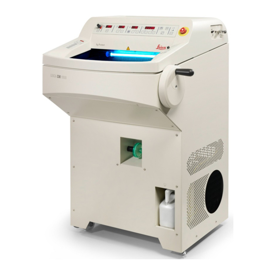
- Page 1 Leica CM1950 Cryostat Instructions for Use English Order No.: 14 0477 80101 - Revision N Always keep this manual with the instrument. Read carefully before working with the instrument.
- Page 3 These are determined only by the contract provisions agreed between ourselves and our customers. Leica reserves the right to change technical specifications as well as manufacturing processes without prior notice. Only in this way is it possible to continuously improve the technology and manufacturing techniques used in our products.
-
Page 4: Table Of Contents
6.5.9 Installing the section extraction (optional) – Use with blade holder CE only ........36 Instrument Controls ..........................Control panels on the Leica CM1950 ......................38 7.1.1 Control panel 1 ............................... 38 7.1.2 Control panel 2 – Electric coarse feed, sectioning and trimming thickness ........40 7.1.3 Control panel 3 –... - Page 5 12.1 General maintenance instructions ......................79 12.2 Changing fuses ............................... 80 12.3 Replacing the UVC lamp ..........................80 12.4 UVC lamp ordering information ........................84 12.5 Replacement of LED illumination ........................ 85 Decontamination Confirmation ......................Warranty and service ..........................Leica CM1950...
-
Page 6: Important Information
Important Information Important Information Symbols in the text and their meanings Warning Symbol: Title of the symbol: Warnings appear in a white box and are marked by a Description: warning triangle. Symbol: Title of the symbol: Note Notes, i. e. important user information, appear in a Description: white box and are marked by an information symbol. -
Page 7: Instrument Type
All information given in these Instructions for Use applies only to the instrument type indicated on the title page. A nameplate indicating the instrument serial number is attached to the rear side of the instrument. Precise data for the various versions is specified in (→ p. 17 – 3. Technical Data). Leica CM1950... -
Page 8: Qualification Of Personnel
Important Information Qualification of personnel The Leica CM1950 may be operated by trained laboratory personnel only. The instrument is intended for professional use only. Prior to operating the instrument, the operator must thoroughly read and understand these Instructions for Use and must familiarize him/herself with all technical details of the instrument. -
Page 9: Safety And Design
Safety and Design Warning The safety and caution notes in this chapter must be observed at all times. Be sure to read these notes even if you are already familiar with the operation and use of other Leica products. Safety notes These Instructions for Use include important instructions and information related to the operating safety and maintenance of the instrument. -
Page 10: General Safety Notes
Note Flammable substances may not be used in the Leica CM1950 when it is turned on and plugged in. Do not place staining solutions or other liquids on top of the instrument. Unpacking and installation... - Page 11 5. Pull the dust cover (→ Fig. 2-5) from the instrument. 6. Remove the two white and the two blue transport anchors (→ Fig. 2-6), which protect the chamber window. 7. Remove all accessories (→ Fig. 2-7). Fig. 2 Leica CM1950...
- Page 12 Safety and Design 8. Lift and remove the wooden edge (→ Fig. 3-9). 9. Remove the ramp (→ Fig. 4-13) from the pallet. 10. Properly insert the ramp. Make sure that the ramp components designated "L" (left) and "R" (right) click into place in the intended guide channel (→...
-
Page 13: Safety Devices
• Before handling the specimen or the knife, or changing the specimen, lock the handwheel and ensure that the knife is covered by the safety guard. • Avoid contact with cold parts of the instrument as this can cause freezer burn – wear the safety gloves supplied! Leica CM1950... -
Page 14: Securing/Locking The Handwheel
Safety and Design Safety guard Warning Prior to making modifications to the knife and specimen, changing the specimen or knife, or taking a break, always lock the handwheel and cover the cutting edge with the safety guard! The CE, CN and CN-Z knife holders feature safety guards; the glass anti-roll plate of the CE knife holder also serves as a safety guard. -
Page 15: Cleaning, Disinfection - Turning The Instrument Back On
• All components removed from the cold cryostat must be carefully dried before returning them to the cryochamber! • The front panel and the slit cover of the microtome must be completely dry before turning on the instrument! Note For more detailed information about disinfection, visit the Leica Biosystems Division website at www.LeicaBiosystems.com Leica CM1950... -
Page 16: Handling Specimens - Defrosting
Safety and Design Handling specimens – Defrosting • When working with contaminated or infected material, the general safety guidelines for laboratories must be applied! • Before defrosting the cryochamber remove all samples! • Before defrosting the specimen head, remove all samples! Note Never leave samples in the cryochamber! –... -
Page 17: Technical Data
Overall size of device, with 835 x 850 x 1215 mm handwheel (width x depth x height) Working height (armrest) 1025 mm Overall size of packging (width x 960 x 820 x 1420 mm depth x height) Leica CM1950... - Page 18 Technical Data Dimensions and weights Empty weight (without 145-193 kg depending on accessories) configuration Environmental specification Operating altitude Max. 2000 m above sea level Operating temperature +18 °C to +35 °C Relative humidity (operation) 20 to 60 % RH non-condensing Transport temperature -29 °C to +50 °C Storage temperature...
- Page 19 (→ p. 41 – Setting section/trim thickness) in acc. with CECOMAF: Liquid temperature 45 °C, evaporation temperature: -25 °C Warning * Refrigerant and compressor oil must be replaced by qualified, authorized service personnel only! Leica CM1950...
- Page 20 Technical Data Microtome Type Rotary microtome, encapsulated Section thickness range 1 to 100 μm Trimming thickness range Clinical: 10 to 40 μm Research: 1 to 600 μm Horizontal specimen feed 25 mm + 1 mm Vertical specimen stroke 59 mm ± 0.5 mm Specimen retraction 20 μm (can be deactivated) Maximum specimen size...
-
Page 21: Standard Delivery
14 0340 29011 Instructions for Use EN + language CD 14 0477 80001 Leica CM1950 "Troubleshooting" DVD 95.10696 Rev A * Note: for the Japanese version: 100 V, 50/60 Hz; 1 pair of safety gloves, size S (14 0340 40859) is included. - Page 22 Compare the delivered components with the parts list and your order. Should you find any discrepancies, please contact your Leica Biosystems sales office without delay. The country specific power cord needs to be ordered separately. Please find a list of all power cords available for your device on our website www.LeicaBiosystems.com within the product section.
- Page 23 Compare the delivered components with the parts list and your order. Should you find any discrepancies, please contact your Leica Biosystems sales office without delay. The country specific power cord needs to be ordered separately. Please find a list of all power cords available for your device on our website www.LeicaBiosystems.com within the product section.
-
Page 24: General Overview
General Overview General Overview Fig. 8 Cryostat chamber (with activated Footswitch dummy (motorized instruments UVC disinfection) only) Bacteria filter (optional, only for instruments Emergency-stop switch (motorized with filter) instruments only) Unscrew and align adjusting feet after Handwheel in 12 o'clock position transport Condenser Castors for safe transport over short... -
Page 25: Control Panel Fields And Cryostat Chamber
17 Adapter piece for extraction hose (the coarse filter insert is behind it) Shelf, movable (optional) 10 Blade holder CE 18 Object head, directional 11 Blade ejector 19 Waste tray 12 Finger rest on the blade holder CE Leica CM1950... -
Page 26: Installation
Installation Installation Site requirements Warning Do not operate the instrument in rooms with explosion hazard. In addition to the requirements listed in (→ p. 17 – 3. Technical Data) the following restrictions apply: • The instrument is designed for indoor use only. • The power plug/circuit breaker must be freely and easily accessible. - Page 27 (→ p. 35 – 6.5.8 Assembling the filter bag)). Warning When not using the extraction for a long period, tightly close the opening for the extraction hose using the silicone stopper included in the standard scope of delivery (→ Fig. 27-6)! Leica CM1950...
-
Page 28: Installing The Handwheel
Installation Transport with a forklift (→ Fig. 11), Total width with handwheel Fig. 11 • The instrument can be transported with a forklift. Warning To ensure a safe transport with a forklift 3 people are required: one operating the forklift, and the other 2 holding the instrument on either side to prevent it from sliding down. -
Page 29: Locking/Unlocking The Handwheel
An important safety device on the cryostat is the feature for centering the handwheel in motorized sectioning mode. To do so, pull out the handwheel's handle and position it in the middle of the handwheel. The handle automatically engages in this position. Fig. 15 Leica CM1950... -
Page 30: Installing The Footswitch Dummy (Instruments With Cutting Motor)
Installation 6.3.2 Installing the footswitch dummy (instruments with cutting motor) • The footswitch dummy must be installed on the outer right side of the instrument (→ p. 24 – 5. General Overview)) if no footswitch (optional) is used. If the red LED (→... -
Page 31: Installing Accessories/Inserting Chamber Accessories
(height). • Once installed, the user can adjust the height of the footrest at any time by relocating it (→ Fig. 19-3) to the desired height on both sides in the holder (→ Fig. 19-2). Leica CM1950... -
Page 32: Installing The Storage Systems (Optional)
Installation 6.5.2 Installing the storage systems (optional) Fig. 20 For reasons of accessibility, the (optional) storage system must always be installed first. To do so, remove the insert (→ Fig. 20-1), place the frame (→ Fig. 20-2) in front of the bore and tighten the screws/washer on the cryostat housing using the size 4 Allen key. -
Page 33: Inserting The Section Waste Tray
(it is better to begin with the bottom screw). Then, rotate the holder upwards (see arrow) and insert and tighten the top screw. Note • Now attach the cover for the quick freeze shelf to protect the shelf from frost. • For temperature reasons, install the knife/blade holder on an appropriate base. Leica CM1950... -
Page 34: Installing The Knife/Blade Holder And Adjusting The Clearance Angle
Installation 6.5.6 Installing the knife/blade holder and adjusting the clearance angle Fig. 24 • Set the knife or blade holder (→ Fig. 24-1) on the base (→ Fig. 24-2), adjust the clearance angle (on the left of the knife/blade holder) to approx. 2° - 5° and secure it in the bore (→... -
Page 35: Inserting/Changing The Bacteria Filter
(→ Fig. 27-4) until there is an audible click. Now push the connected parts back into the opening in the cryostat chamber (filter first) and set it to the "closed" mark (→ Fig. 27-3). Leica CM1950... -
Page 36: Installing The Section Extraction (Optional) - Use With Blade Holder Ce Only
Installation Fig. 27 Note When not using the extraction, tightly close the opening for the extraction hose using the silicone stopper (→ Fig. 27-6) included in the scope of delivery. Reasons: 1. To prevent section waste from falling into the opening. 2. - Page 37 • If the extraction is not used for a long time, it is absolutely necessary to clean the extraction hose in order to ensure maximum extraction capacity. To do so, place the hose in commercially available disinfectant or alcohol. After several cleanings, the hose must be replaced (→ p. 61 – 11.1 Ordering information)! Leica CM1950...
-
Page 38: Instrument Controls
Instrument Controls Instrument Controls Control panels on the Leica CM1950 7.1.1 Control panel 1 Fig. 30 Extraction force intensity selectable from 1-5 +/- buttons to select chamber temperature (see following page for more information) 10 Max-Cool button to select the maximum low... - Page 39 When the condenser starts up, the flashing stops and the 10 minutes are counted down. • (For exact instructions for using the chamber, specimen head and real time display fields, refer to the chapter on (→ p. 45 – 8. Working with the Instrument)). Leica CM1950...
-
Page 40: Control Panel 2 - Electric Coarse Feed, Sectioning And Trimming Thickness
Instrument Controls 7.1.2 Control panel 2 – Electric coarse feed, sectioning and trimming thickness Illuminates in yellow when the specimen is in retraction. Move specimen head backwards quickly to home position (latched) Move specimen head backwards slowly – pressing briefly retracts the specimen 20 μm Specimen head forwards –... - Page 41 • Start the fast forwards movement to the knife. • The LED (→ Fig. 32-10) flashes while the specimen head is in motion. The LED (→ Fig. 32-10) lights up when the forward end position has been reached. fast Leica CM1950...
-
Page 42: Control Panel 3 - Motorized Sectioning (Optional)
Instrument Controls Manual sectioning mode Select ROCK operating mode (→ Fig. 32-6) (LED active) – retraction must be enabled! • For sectioning, turn the handwheel a short distance (approx. 1/4 turn) forwards and back (rocking mode) – only possible at rear (handwheel in approx. 12 - 3 o'clock position). Every change in rotation direction is electronically detected and automatically translated into a specimen feed or retraction movement. - Page 43 To start disinfection, the sliding window must be completely closed. • Press button once briefly to start the 30 min. mode • button – press 1x for a longer time (approx. 4 sec), 180 min mode For current information about certificates and recommendations, visit www.leicabiosystems.com. Leica CM1950...
- Page 44 Instrument Controls Warning UVC disinfection is effective when disinfecting surfaces and air within the irradiated working area of the Leica CM1850 UV, CM1900 UV and Leica CM1950 cryostats at -20 °C (Table 1, see Certificate from Maier). For powerful disinfection, we recommend irradiation for three hours (CM1850 UV/Leica CM1950) and four hours (CM1900 UV).
-
Page 45: Working With The Instrument
The circuit breaker also serves as the power switch. The switch must be in the top position for switching on and in the bottom position for switching off. The switch must be accessible without obstruction. • Close the sliding window. Fig. 36 Leica CM1950... -
Page 46: Configuring The Parameters
Working with the Instrument Note To avoid frost formation always put the cover on the quick freeze shelf. Always cover the quick freeze shelf during breaks and overnight. Configuring the parameters Note The instrument must be switched on at least 5 hours before the planned use. • Turns the LED illumination on or off. - Page 47 • Set the beginning of the automatic defrost cycle. The automatic defrost cycle takes place once within 24 hours. It is set with the "+"/"-" buttons on the right of the panel with the clock symbol. The two buttons are marked by a melting snowflake Leica CM1950...
- Page 48 Working with the Instrument • Briefly press the "+" or "-" button for indication of the beginning of the defrost cycle which has actually been set. At the same time, the LEDs between the indication of hours and minutes are flashing. • To change the beginning of the defrost cycle in steps of 15 minutes, push the "+"...
- Page 49 To switch from a trimming section thickness for research applications (1 - 600 μm) to a thickness for clinical applications (10, 20, 30 or 40 μm), press and hold down the button (→ Fig. 32-7) TRIM/SECT while switching on the instrument. Leica CM1950...
-
Page 50: Working With The Precooled Cryostat
Working with the Instrument • Press the TRIM/SECT button. TRIM mode is active if the LED at the top right is illuminated. • Set the desired trimming thickness using the "+" or "-" button in control panel 2 (for the adjustable sequence of steps, see (→... - Page 51 • Move the locking lever for orientation back to the right to lock the specimen head and make sure that the specimen head is now stable. Fig. 39 • Repeat the procedure if necessary. Leica CM1950...
- Page 52 Working with the Instrument Note Check the stability of the specimen head each time it clicks back into place. This can prevent it from becoming difficult to set the zero position. Fig. 40 Note Before using them for the first time, degrease new knives using acetone or alcohol. • Approach the specimen with the knife or blade holder: • To do so, open the clamping lever of the base, approach the specimen and close the lever again.
-
Page 53: Trimming With Extraction - 1. Anti-Roll Guide Installed
• Check that the anti-roll guide is parallel and correctly adjusted. Read just if necessary (→ p. 67 – Adjusting the blade holder with anti-roll guide). • Activate trimming mode. • Select the trimming thickness. • Switch on the VAC and select a low extraction level (between 1 and 2). Leica CM1950... - Page 54 Working with the Instrument • Start trimming by manually moving the handwheel or press the RUN/STOP buttons simultaneously to start motorized sectioning. ENABLE Note For motorized sectioning, always begin at low speed for safety reasons. • Optimize the vacuum settings if necessary. • Press the button to enable the vacuum extractor.
-
Page 55: Cutting With Extraction - Anti-Roll Guide Installed
• The larger and/or thicker the specimen to be trimmed, the lower the extraction value. • For section specimens with a diameter of 0.5 cm, the anti-roll guide stretches the section adequately. For larger specimens, we recommend using the vacuum function. Leica CM1950... - Page 56 Working with the Instrument After trimming or sectioning: Specimen: • Unclamp and thaw. • Immerse in fixative for further processing. Cleaning: • Use the brush to sweep up the section waste (section waste tray) and remove it from the cryostat (follow applicable laboratory regulations for disposal).
-
Page 57: Troubleshooting
Knife/blade damaged. Edge of anti-roll plate damaged. Chatter during sectioning Specimen insufficiently frozen Refreeze specimen onto the onto the specimen disc. disc. Specimen disc not clamped Check disc clamping. tightly. Knife not clamped tightly Check knife clamping. enough. Leica CM1950... - Page 58 Troubleshooting Problem Cause Remedy Specimen has been sectioned Refreeze specimen onto the too thickly and has detached disc. from disc. Very hard, inhomogenous Increase section thickness; specimen. reduce specimen surface area if necessary. Blunt knife. Use different part of the knife. Knife profile inappropriate for Use knife with different profile.
- Page 59 UVC radiation provided by Replace UVC lamp following the alternately UVC lamp no longer sufficient. manufacturer’s instructions. Image of an open-ended wrench Contact technical service and appears due to fault to be follow the instructions given. rectified Fig. 47 Leica CM1950...
-
Page 60: Temperature Selection Chart
Temperature selection chart Temperature selection chart Tissue type Chamber temperature Specimen head temperature Spleen -15 °C to -20 °C -11 °C Liver -10 °C -20 °C -15 °C off until -15 °C -10 °C -20 °C Intestine -15 °C A*: off until -20 °C E*: -20 °C -10 °C A: -20 °C... -
Page 61: Optional Accessories
14 0477 43737 Heat extractor, assembly 14 0477 43126 Section waste tray 14 0477 40062 Brush shelf 14 0477 43036 Storage system, assembly 14 0477 42618 Shelf, movable 14 0477 43037 Retaining device freezing shelf 14 0477 40080 Leica CM1950... - Page 62 Optional Accessories Part No. Cover freezing shelf 14 0477 43763 Specimen disc, 37 x 37 mm 14 0477 42603 Specimen disc, 28 x 28 mm 14 0477 42604 Shelf, large 14 0477 42600 Shelf, medium size 14 0477 42601 Shelf, small 14 0477 42602 Heat extractor, Dr.Peters, assembly 14 0477 41338...
- Page 63 4. Screw the knurled nut (→ Fig. 49-4) from below onto the shaft (→ Fig. 49-3). Note The glass of the anti-roll guide can be used from all 4 sides when replacement is necessary (the glass stage plate can be reordered). Leica CM1950...
- Page 64 Optional Accessories Fig. 50 Note Red elements on the blade and knife holders, such as the safety guard and ejector, are protective devices that may not be removed. The anti-roll guide (→ Fig. 50-9) and pressure plate (→ Fig. 50-8) must be parallel to each other.
- Page 65 Make sure that the blade is inserted so that it is centered. 4. Rotate lever (→ Fig. 52-5) clockwise to clamp. 5. Fold the anti-roll guide system (→ Fig. 52-2) back to the right (toward the blade) using the lever (→ Fig. 52-3). Fig. 53 Leica CM1950...
- Page 66 Optional Accessories Note Anti-roll guide system functions as a safety guard here! Use the blade ejector (→ Fig. 53-12) to eject the blade! Magnet Fig. 54 6. Another option for removing the blade is to use the brush with magnet (→...
- Page 67 Fig. 57 Adjusting the blade holder with anti-roll guide (→ Fig. 58), Blade holder CE with glass anti-roll guide Fig. 58 You can adjust the height of the anti-roll guide system using the knurled nut (→ Fig. 58-10): Leica CM1950...
- Page 68 Optional Accessories • If you turn the nut counterclockwise, the antiroll guide system moves toward the blade. • If you turn the nut clockwise, the anti-roll guide system moves away from the blade. If the anti-roll guide system is in the wrong position relative to the cutter, the following problems will result: The section rolls over the glass insert of the anti-roll guide system.
- Page 69 For daily cleaning, it is enough to fold the anti-roll guide system forwards and remove the section waste from the knife holder using a dry brush. Please use a cold brush, as otherwise the section waste will thaw and stick to the knife holder. Leica CM1950...
- Page 70 Optional Accessories Note It is not necessary to oil parts, such as the T-piece on the microtome base plate, clamping lever etc. Disinfection Warning Before switching on the instrument again, proper ventilation of the chamber shall be ensured. Ensure that the chamber is completely dry and ventilated before you plug the instrument back in and turn it Wipe the contaminated surfaces with a paper towel soaked in an alcohol based disinfectant.
- Page 71 (→ Fig. 61-4). Warning Never work with only one clamping jaw, as this does not ensure the stability required for the sectioning process. Also, a long knife will not be sufficiently protected by the safety guard in this instance. Leica CM1950...
- Page 72 Optional Accessories Safety guard/lateral movement for knife holder CN Fig. 64 The safety guard (→ Fig. 64-10) is fixed and integrated into the clamping jaws. The safety guard has handles (→ Fig. 64-11) that allow it to be moved. The safety guard is adequate for knives up to 22 cm in length.
- Page 73 The 50 μm and 100 μm anti-roll plates are included in the standard scope of delivery of the blade holder CE. Straightedge (blade rest) Insert for low-profile blades for blade holder CE (14 0477 43005) replacement Fig. 68 Note The blade rest is also included in the standard scope of delivery of the blade holder CE. Leica CM1950...
- Page 74 Optional Accessories When using low-profile blades, the blade rest (→ Fig. 51-11) must be inserted into the blade holder CE first, then the low-profile blade. Bacteria filter Bacteria filter 350/5865, pack of 1. Recommendation: bacteria filters should be replaced every 3 months. (Write the installation date on the filter) Fig.
- Page 75 ø 30 ø 20 mm • Specimen discs in various dimensions Fig. 73 Note The specimen disc 50 x 80 mm is suitable only for section thicknesses up to approx. 5 μm (due to the large specimen size). Leica CM1950...
- Page 76 Optional Accessories O-rings in various colors • for plate Ø 20 mm (red or blue), 10x each • for plate Ø 30 mm (red or blue), 10x each • for plate Ø 40 mm (red or blue), 10x each • for plate Ø 55 mm (red or blue), 10x each for labeling specimen discs using color Fig.
- Page 77 E-STOP field on the instrument is lit up as long as the foot switch remains depressed. • To resume the sectioning process, select the sectioning type (CONT or SINGLE) and restart the system using the foot switch. Leica CM1950...
- Page 78 Optional Accessories Footrest, individually height-adjustable footrest with 5 adjustment options. Fig. 78 Brush shelf, for use with blade holder CE Fig. 79 Storage system, movable for installation in the front part of the cryostat for cooled storage of preparation aids Fig.
-
Page 79: Maintenance And Cleaning
• At least ONCE a year, have the instrument inspected by a qualified service engineer authorized by Leica. • Enter into a service contract at the end of the warranty period. For more information, please contact your local Leica technical service center. • Clean the instrument daily. Warning If completely defrosted, bacteria filters and filter bags MUST be removed. -
Page 80: Changing Fuses
• All parts that have been removed from the cold cryostat must be dried thoroughly before they are put back into the chamber. 12.2 Changing fuses • In case of power supply faults, please contact an authorized Leica service technician immediately. Warning Do not carry out any repairs on your own as this will invalidate the warranty. - Page 81 Note For the Leica CM1950, two different variants of the connection piece inside the instrument and the UVC-Lamp are available. You need to check which variant is built-in in the instrument prior to the exchange of the UVC lamp with a new one.
- Page 82 Maintenance and Cleaning Fig. 83 Variant 2: Connection piece with 4-pin inlet (→ Fig. 84-1), UVC lamp 4-pin (→ Fig. 84-2). Fig. 84 Removal of the lamp The UVC lamp (→ Fig. 85-3) is installed in front of the protection screen for chamber illumination (→...
- Page 83 • Screw the metal ring onto the holder, then hold the lamp with both hands and carefully push it into the clips (→ Fig. 85-5). • Replace the sliding window. • Connect the instrument to the power supply again and switch it on. Leica CM1950...
-
Page 84: Uvc Lamp Ordering Information
Maintenance and Cleaning Fig. 87 Note If the UVC button is depressed for more than 30 seconds, the running-time meter for the UVC lamp is reset. This is required every time the UVC lamp is replaced to ensure sufficient power for disinfection! Warning Dispose of the UVC lamp separately! -
Page 85: Replacement Of Led Illumination
Order No.: 14 0471 57385 Fig. 89 12.5 Replacement of LED illumination The LED illumination is designed for maximum life span. In case of damage, please contact Leica customer service to arrange replacement. For further details, see (→ p. 87 – 14. Warranty and service). -
Page 86: Decontamination Confirmation
Decontamination Confirmation Decontamination Confirmation Every product that is returned to Leica Biosystems or that requires on-site maintenance must be properly cleaned and decontaminated. You can find the dedicated template of the decontamination confirmation on our website www.LeicaBiosystems.com within the product menu. This template has to be used for gathering all required data. -
Page 87: Warranty And Service
Leica sales organization or the organization from which you have purchased the contractual product shall apply exclusively. Service information If you are in need of technical customer support or spare parts, please contact your Leica representative or the Leica dealer where you purchased the instrument. Please provide the following information: • Model name and serial number of the instrument... - Page 88 Note Version 2.1, Revision N...
- Page 90 Leica Biosystems Nussloch GmbH Heidelberger Strasse 17 - 19 69226 Nussloch Germany Tel.: +49 - (0) 6224 - 143 0 Fax: +49 - (0) 6224 - 143 268 Web: www.LeicaBiosystems.com...
Need help?
Do you have a question about the CM1950 and is the answer not in the manual?
Questions and answers