
Related Manuals for Leica CM1950


Summary of Contents for Leica CM1950
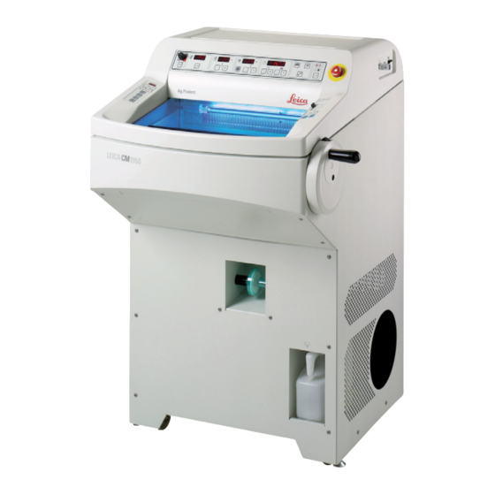
- Page 1 Leica CM1950 Cryostat Instructions for Use Leica CM1950 , 1v4 English – 10/2012 Order number 14 0477 80101 RevE Always keep these instructions near the instrument! Read carefully before working with the instrument.
- Page 3 Leica reserves the right to change technical spec- following thorough investigation in this field. We ifications as well as manufacturing processes are under no obligation to update the present without prior notice.
-
Page 4: Table Of Contents
Table of Contents Important information....................6 Symbols in the text and their meanings...............6 Instrument type........................6 Qualification of personnel....................7 Intended use of the instrument..................7 Safety and design......................8 Safety notes........................8 Warnings...........................8 General safety notes.......................9 Unpacking and installation.....................9 Safety devices. - Page 5 6.5.9 Installing the section extraction (optional) – Use with blade holder CE only....32 Instrument controls......................... 33 Control panel fields on the CM1950 – Control panel field 1..........33 Control panel field 2 – Electric coarse feed, sectioning and trimming thickness display......................
-
Page 6: Important Information
Important information Symbols in the text and their meanings Environmental protection symbol of the China RoHS directive. The number in Warnings the symbol indicates the "Environment- appear in a gray box and are marked friendly Use Period" of the product. The by a warning triangle symbol is used if a substance restricted in China is used in excess of the maxi-... -
Page 7: Qualification Of Personnel
Important Information Qualification of personnel Intended use of the instrument The Leica CM1950 may be operated by trained The CM1950 is a high-performance cryostat with laboratory personnel only. an encapsulated microtome and separate speci- men cooling. It features a UV disinfection system,... -
Page 8: Safety And Design
The safety and caution notes in this chapter must be observed at all times. Be sure to read these notes even if you are already familiar with the operation and use of other Leica products. Safety notes To maintain this condition and ensure safe opera-... -
Page 9: General Safety Notes
Safety and design General safety notes The CM1950 is a cryostat with an encapsulated microtome and separate specimen cooling. It is primarily used for work in the area of fast-cut diag- nostics. The displays and instrument controls are easy to operate due to their largely self-explanatory symbols. - Page 10 Safety and design When the instrument is delivered, check the tilt indicators on the packaging. If the arrowhead is blue, the shipment was transported laying flat, was tilted at too great an angle or fell over during transport. Note this on the shipping documents and check the shipment for possible damage.
- Page 11 The rollers (14) must run over the cover hinges (2) at the front and rear. Danger of tipping! 1. Carefully roll the instrument backwards over the ramp from the pallet. 2. Push the instrument to the installation location on the castors (14). Fig. 6 Leica CM1950 – Cryostat...
-
Page 12: Safety Devices
Safety and design Safety devices The Instructions for Use include important instructions and information related to the operating safety and maintenance of the instrument. These Instructions for Use are an important part of the product, and must be read carefully before startup and use and must always be kept near the instrument. If additional requirements on accident prevention and environmental protection apply in the country of operation, these Instructions for Use must be supplement- ed by appropriate instructions to ensure compliance with such requirements. -
Page 13: Securing/Locking The Handwheel
The handle automatically engages in this position. An important safety device on the cryostat is the centering of the handwheel for motorized instruments. Rotate the handwheel only if the refrigeration system is on and the Fig. 9 cryochamber is cold. Leica CM1950 – Cryostat... -
Page 14: Cleaning, Disinfection - Turning The Instrument Back On
It is not necessary to remove the microtome for disinfection. • The instrument has been designed for UV disinfection! Spray disinfection with Leica Cryofect is also possible, thanks to the special insulation of the microtome. (Cryofect is not available in all countries!) Remove section waste after EVERY sectioning operation and BEFORE changing specimens. -
Page 15: Handling Specimens - Defrosting
Technical Service. If any metallic mercury is released, handle it carefully and dispose of it properly. If both disinfection indicator lights are blinking alternately, the UV tube must be replaced! Leica CM1950 – Cryostat... -
Page 16: Technical Data
Technical data All specifications related to temperature are valid only up to an ambient temperature of 18 °C to 35 °C and a relative humidity of no more than 60%. Instrument type Nominal voltage (±10%) 100 VAC 120 VAC 230 VAC Nominal frequency 50/60 Hz 60 Hz... - Page 17 Technical data Refrigeration system CM1950 , 50 Hz CM1950, 60 Hz Cryochamber Temperature range 0 °C to -35 °C ± 5 K, adjustable in 1K increments, 0 °C to -35 °C ± 5 K, adjustable in 1K incre- at an ambient temperature of 20 °C ments, ambient temperature of 20 °C...
-
Page 18: Standard Delivery
- Set of filters (5 pieces) ................ 14 0477 43792 Compare the delivered components with the parts list and your order. Should there be any discrepancy, please contact the Leica Biosystems selling unit handling your order immediately. A choice of different blade/knife holders is available for the CM1950 . - Page 19 - Set of filters (5 pieces) ................ 14 0477 43792 Compare the delivered components with the parts list and your order. Should there be any discrepancy, please contact the Leica Biosystems selling unit handling your order immediately. A choice of different blade/knife holders is available for the CM1950 .
-
Page 20: General Overview
General Overview Emergency-stop On/off switch, also switch (motorized circuit breaker instruments only) Footswitch Cryostat chamber dummy (with activated (motorized UV disinfection) instruments only) Handwheel in 12 o'clock position Bacteria filter (optional, only for instruments with filter) Condenser Unscrew and align Catch tank adjusting feet after for condensate... -
Page 21: Control Panel Fields And Cryostat Chamber
14 Adapter piece for extraction hose Shelf, movable (optional) (the coarse filter insert is behind it) 10 Blade holder CE with blade ejector (a) 15 Object head, directional 10b Finger rest on the blade holder CE 16 Waste tray Leica CM1950 – Cryostat... -
Page 22: Installation
Installation Site requirements Do not operate the instrument in rooms with explosion hazard. The place of installation must meet the following requirements: - The instrument requires an installation area of approx. 835 x 850 mm, - Room volume must be at least 8 m - Room temperature consistently 18 °C to 35 °C, - Temperature range during storage: 5 °C to 55 °C, - Relative humidity, maximum 60% (non-condensing) -
Page 23: Transport To The Site
(Refer also to p. Fig. 12 When not using the extraction for a long period, tightly close the opening for the extraction hose using the silicone stop- per (E, page 31)! Leica CM1950 – Cryostat... -
Page 24: Assembling The Handwheel
Installation Transport with a fork lift • The instrument can be transported with a fork lift. To ensure a safe transport with a fork lift 3 people are required: one operating the fork lift, and the other 2 holding the instrument on either side to prevent it from sliding down. • At the installation location, unscrew the adjusting feet (1) (see Fig. -
Page 25: Locking/Unlocking The Handwheel
• The footswitch dummy must be installed on the outer right side of the instrument (see page 16, General overview) if no footswitch (optional) is used. If the red LED in the E-STOP field in control panel field 3 is illuminated, either: • emergency-stop function active, or • Footswitch dummy (opt. foot switch) not connected or incorrectly con- Fig. 18 nected. Leica CM1950 – Cryostat... -
Page 26: Electrical Connection
Installation Electrical connection After transporting, wait at least 4 hours before turning the instrument on. This waiting period is necessary to allow the compressor oil, which may have been displaced during transport, to return into its original position. Furthermore, any condensation that has formed during this time due to temperature fluctuations must be allowed to dry completely. -
Page 27: Installing Accessories/Inserting Chamber Accessories
• Hook the footrest (3) into the installed holder according to individual requirements (height). • Once installed, the user can adjust the height of the footrest at any time by relocating it (3) to the desired height on both sides in the holder (2). Fig. 20 Leica CM1950 – Cryostat... -
Page 28: Installing The Storage Systems (Optional)
Installation 6.5.2 Installing the storage systems (optional) F o r r e a s o n s o f accessibility, the (optional) storage system must always be installed first. To do so, remove the insert (1), place the frame (2) in front of the bore and tighten the screws/ washers on the cryostat housing using the No. -
Page 29: Installing The Heat Extractor, Stationary (Optional)
(2), adjust the clearance angle (on the left of the knife/blade holder) to approx. 2° - 5° and secure it in the bore (3) on the base (2) using the No. 4 Allen key. Fig. 25 Leica CM1950 – Cryostat... - Page 30 Installation • Push the knife/blade holder base (2) on the dovetail guide (4) from the front and tighten it using the clamping lever (5). Move the clamp- ing lever clockwise (toward the closed lock symbol) on the right side of the blade/knife holder base (see Detail of Fig.
-
Page 31: Inserting/Changing The Bacteria Filter
Reasons: 1. To prevent section waste from falling into the opening. 2. To prevent cold from escaping from the cham- ber. 3. To prevent moisture from penetrating the Fig. 29 chamber. Leica CM1950 – Cryostat... -
Page 32: Installing The Section Extraction (Optional) - Use With Blade Holder Ce Only
Installation 6.5.9 Installing the section extraction (optional) – Use with blade holder CE only When the suction nozzles are changed, the adapter (white) remains in the silicone hose. Pull off the nozzle by rotating and pulling it gently and firmly plug in the desired nozzle. Ensure that the hose with the nozzle is not installed against its "natural"... -
Page 33: Instrument Controls
Instrument controls Control panel fields on the CM1950 – Control panel field 1 Display of real time, defrost time Display of actual and target chamber Display of actual and target specimen temperatures head temperatures and error messages Fig. 33 "Melting... - Page 34 Instrument controls • Press the "VAC" button to enable the vacuum extractor. The LED in the "VAC" button is lit while the extractor is on. Press the button again to 12 o'clock disable it. • Use the knob to adjust the intensity of the vacuum. Position A Optimal area for trimming and sectioning 6 o'clock • Trimming: Handwheel position 12 – 6 o'clock, valve open Handwheel position 6 –...
-
Page 35: Control Panel Field 2 - Electric Coarse Feed, Sectioning And Trimming Thickness Display
10.0 µm increments 60.0 µm – 100.0 µm 10.0 µm increments 100.0 µm – 600.0 µm 50.0 µm increments Trimming section thickness setting range: (Recommended for clinical applications) Values: 10 µm, 20 µm, 30 µm, 40 µm. Leica CM1950 – Cryostat... - Page 36 Instrument controls Coarse feed functions The electric coarse feed at two speeds is used for a rapid movement of the specimen towards and away from the knife. With the double-arrow buttons, the coarse feed operates at 900 µm/s; with the single-arrow buttons, it runs at 300 µm/s.
-
Page 37: Control Panel Field 3 - Motorized Sectioning (Optional)
The following settings are available: • Single stroke (SINGLE) or continuous stroke (CONT.) in motorized mode, as well as • ROCK (sectioning using handwheel) in manual mode. When switching the instrument on, no operating mode is active for safety reasons. Leica CM1950 – Cryostat... - Page 38 UVC disinfection is effective when disinfecting surfaces and air within the irradiated working area of the Leica CM1850 UV, CM1900UV and CM1950 cryostats at -20 °C (Table 1, see Certificate I. Maier). For powerful disinfection, we recommend irradiation for three hours (CM1850UV/CM1950) and four hours (CM1900UV).
-
Page 39: Working With The Instrument
The switch must be accessible without obstruction. • Close the sliding window. Fig. 41 To avoid frost formation always put the cover on the quick freeze shelf. Always cover the quick freeze shelf during breaks and overnight. Leica CM1950 – Cryostat... -
Page 40: Configuring The Parameters
Working with the Instrument Configuring the parameters The instrument must be switched on at least 5 hours before the planned use. • Turn the lamp on or off. • This button activates or deactivates the manual defrost of the cooling chamber, specimen head or freeze shelf. (For more detailed handling instructions, refer to the chapter on "Working with the Instrument" on p. - Page 41 To do so, set the current time using the "+" or "-" button below the small clock symbol. Pushing the "+" or "-" button for more than 1 sec. increases or decreases the time continuously (auto-repeat function). Fig. 45 Leica CM1950 – Cryostat...
- Page 42 Working with the instrument Programming the defrost cycle • Set the beginning of the automatic defrost cycle. The automatic defrost cycle takes place once within 24 hours. It is set with the "+"/"-" buttons on the right of the panel with the clock symbol. The two buttons are marked by a melting snowflake • Briefly press the "+" or "-" button for indication of the beginning of the defrost cycle which has actually been set.
- Page 43 • If necessary, push the manual defrost button again to deactivate the manual defrost cycle. Press the key button, then the "+" button = specimen head on Press the key button, then the "-" button = specimen head off Leica CM1950 – Cryostat...
- Page 44 Working with the instrument Entering the trimming thickness To switch from a trimming section thickness for research applica- tions (1- 600 µm) to a thickness for clinical applications (10, 20, 30 or 40 µm), press and hold down the TRIM/SECT key while switch- ing on the instrument.
-
Page 45: Working With The Precooled Cryostat
(2) to the left to loosen the • Repeat the procedure if necessary. specimen head. • Now turn the setscrew (3) on the bottom of the specimen head clockwise until you feel the specimen head click into place. Leica CM1950 – Cryostat... -
Page 46: Trimming With Extraction - 1. Anti-Roll Guide Installed
Working with the Instrument Check the stability of the specimen head each time it clicks back into place. This can prevent it from becoming difficult to set the zero position. Before using them for the first time, degrease new knives using acetone or alcohol. - Page 47 • Sectioning: Handwheel position 12 – 3 o'clock, valve open all the way Fig. 58 Handwheel position 3 – 6 o'clock, valve half open Handwheel position 6 – 12 o'clock, valve closed B Optimal area for extraction from the chamber • To clean the chamber, turn the knob to the red range. Leica CM1950 – Cryostat...
- Page 48 Working with the instrument If the handwheel is not moved for approx. 5 sec, the valves close and the fan remains on. If the handwheel is moved for approx. 1 min, the valves close, the fan shuts off (the LED in the VAC switch goes off to prevent icing).
-
Page 49: Cutting With Extraction - Anti-Roll Guide Installed
• The larger and/or thicker the specimen to be trimmed, the lower the extraction value. • For section specimens with a diameter of 0.5 cm, the anti-roll guide stretches the section adequately. For larger specimens, we recommend using the vacuum function. Leica CM1950 – Cryostat... - Page 50 • M ove the anti-roll guide to the side (see Fig. 61). • Spray the cryostat chamber using Cryofect. Fig. 61 • Activate the UVC disinfection. The use of flammable sprays within the cryostat chamber is permitted only with the Leica Cryofect tested by us. Instructions for Use 1v4 – 10/2012...
-
Page 51: Troubleshooting
Anti-roll plate does not protrude far Readjust correctly. plate enough beyond the knife edge. Scraping noise during Anti-roll plate protrudes too far Readjust correctly. sectioning and specimen beyond the knife edge and is scraping return movement against the specimen. Leica CM1950 – Cryostat... - Page 52 Troubleshooting Problem Cause Remedy Ridged sections Cryostat is exposed to air currents Use different part of the knife. (open windows and doors, air Replace anti-roll plate. conditioning). Frost built-up by breathing into the cryochamber. Chatter during sectioning Specimen insufficiently frozen onto Refreeze specimen onto the disc.
- Page 53 If not possible, call technical service. Specimen disc cannot be Moisture on the underside causes Apply concentrated alcohol to the removed the specimen to freeze to the freezing contact point. shelf or specimen head. Leica CM1950 – Cryostat...
- Page 54 Troubleshooting Problem Cause Remedy No or insufficient Cooling system or electronic drive Call technical service. refrigeration of the defective. cryochamber Sliding window collects Air humidity and room temperature too Comply with the requirements for condensation high. the installation site. No or insufficient Cooling system or electronic drive Call technical service.
-
Page 55: Temperature Selection Chart (In Minus °C)
Brain -15 °C -10 °C, *E *A = blocked, *E = complete The temperature values given in this table are based on experience, however, these are only approximate values, as any tissue may require particular adjustments. Leica CM1950 – Cryostat... -
Page 56: Optional Accessories
Hose set, 5 pieces ................14 0477 44469 Filter assembly 25 pieces, with coarse filter insert ....14 0477 44307 VPE Leica Cryofect, 4x 350 ml ............14 0387 42801 Safety gloves size M ............... 14 0340 29011 Safety gloves size S ................ 14 0340 40859 Footswitch, dummy plug CM3050 .......... -
Page 57: Ordering Information
Knife support CN ................14 0477 42370 Knife holder attachment CN-Z, assembly........14 0477 42363 Anti-roll plate assembly glass 50 mm ........... 14 0419 33981 Heat and cold extractor, assembly ..........14 0477 41039 Cold extractor, assembly ..............14 0477 43737 Leica CM1950 – Cryostat... - Page 58 Optional accessories Bladeholder CE with anti-roll guide (for low-profile, LP, and high-profile, HP) • With blade ejector (1) • With knife guard (2) • integrated lateral shift and stable base • Clearance angle adjustment (5) with Allen key No. 4 (see detail image to left at knife holder) – recommended angle between 2° and 5°. • With anti-roll guide (4) • Lever (6) for the lateral shift • Lever (7) for clamping the blade...
- Page 59 No. 2.5 key – be careful of the blade ejector! Four possible settings If you are working with the brush technique, the knife guard must be folded upwards. Fig. 66 Leica CM1950 – Cryostat...
- Page 60 Optional accessories Inserting/ejecting the blade into/from the knife holder CE The safety gloves included in the stan- dard scope of delivery must be worn when inserting the blade! 1. Fold the anti-roll guide system (4) to the left – while doing so, hold the lever (11) (not the adjusting screw of the anti-roll guide) so that the height of the anti-roll guide remains un- changed.
- Page 61 (3-point click stop enables you to accurately find a new cutting position). 2. Fold the clamping lever (8) forwards for Fig. 69 clamping. Knife holder CN with glass anti- roll guide Fig. 69a Leica CM1950 – Cryostat...
- Page 62 Optional accessories Adjusting the knife holder with anti-roll guide You can adjust the height of the anti-roll guide system using the knurled nut (1): • If you turn the nut counterclockwise, the anti- roll guide system moves toward the blade. • If you turn the nut clockwise, the anti-roll guide system moves away from the blade. If the anti-roll guide system is in the wrong posi- tion relative to the cutter, the following problems will result:...
- Page 63 15 minutes, then wipe it off. The use of flammable sprays within the cryostat chamber is permitted only with the Leica Cryofect tested by us. Leica CM1950 – Cryostat...
- Page 64 Optional accessories Knife holder CN with anti-roll guide – Moving the clamping jaws and inserting the knife The specimen disc 50 x 80 mm is suit- able only for section thicknesses up to approx. 5 µm (due to the large specimen size).
- Page 65 After removing the knife from the knife holder, place it safely into the knife case. NEVER place it onto the work surface next to the instrument! Fig. 76 Leica CM1950 – Cryostat...
- Page 66 Optional accessories Anti-roll guide system Anti-roll plate (with glass stage plate) Available with various spacers: • 70 mm - 50 µm, for section thickness: < 4 µm • 70 mm - 100 µm, for section thickness: 5 µm - 50 µm • 70 mm - 150 µm, for section thickness: > 50 µm The 50 µm and 100 µm anti-roll plates are included in the standard scope of Fig. 77 delivery of the blade holder CE. Straightedge (blade rest) Insert for low-profile blades for blade holder CE (14 0477 43005) replacement...
- Page 67 G - Plastic clip (for parking the extraction nozzle) Fig. 81 Storage system, complete ("hidden") • Storage system for installation in the rear part of the cryostat for cooled storage of specimen discs and cutting accessories (For assembly, refer to page 28) Fig. 82 Leica CM1950 – Cryostat...
- Page 68 Optional accessories • Specimen discs in various dimensions The specimen disc 50 x 80 mm is suit- able only for section thicknesses up to approx. 5 µm (due to the large specimen size). 50 x80 mm ø 55 ø 40 ø 30 ø 20mm O-rings in various colors • for plate Ø 20 mm (red or blue), 10x each • for plate Ø 30 mm (red or blue), 10x each...
- Page 69 The red LED in the E-STOP field on the instrument (Fig. 38) is lit up as long as the foot switch remains depressed. • To resume the sectioning process, select the sectioning type (CONT or SINGLE) and restart the system using the foot switch. Leica CM1950 – Cryostat...
- Page 70 Optional accessories Footrest, individually height-adjustable footrest with 5 ad- justment options. Fig. 87 Brush shelf, for use with blade holder CE Fig. 88 Storage system, movable for installation in the front part of the cryostat for cooled storage of preparation aids Fig.
-
Page 71: Maintenance And Cleaning
• At least once a year, have the instrument inspected by a qualified service engineer authorized by Leica. • Enter into a service contract at the end of the warranty period. For more information, please contact your local Leica technical service center. • Clean the instrument daily. If completely defrosted, bacteria filters and filter bags must be re- moved, as melted coverslip mountant clogs the extraction line. - Page 72 Fig. 90 Basically, we recommend UV disinfection (see page 38). For easy-to-use spray disinfection we recommend Leica Cryofect. (Cryofect is not available in all countries!) The cryostat has to be disinfected after each daily use. Comply with the instructions for use! The glass anti-roll plate can remain in place during disinfection.
-
Page 73: Changing Fuses
When both LEDs (short and long-term disinfection) are blinking alternately in control panel field 1, the lamp must be replaced. • Switch off the instrument at the circuit breaker. • Disconnect the power plug. • Slightly lift the sliding window (1) using the grip (2) and pull it out to the front. Fig. 91 Leica CM1950 – Cryostat... - Page 74 Maintenance and cleaning Removal of the lamp The UVC lamp (3) is installed in front of the protection screen for chamber illumination (4). • Hold the lamp with both hands and carefully pull it out of the clips (5) with a slight forward movement. • Detach the metal ring (7) on the holder (6) in direction of the arrow (8) and carefully pull the lamp out of Fig.
-
Page 75: Replacing The Fluorescent Lamp
Only use lamps of the same specifica- tion! Installation of the new lamp Type: OSRAM DULUX L 18W/ 840. Fig. 97 • Hold the lamp in the correct mounting posi- tion, as shown, and push it to the right until it engages in the holder. Leica CM1950 – Cryostat... -
Page 76: Decontamination Certificate (Master)
(Master) Dear Customer, Any product which is to be returned to Leica Biosystems or serviced on site, must be cleaned and decontaminated in the appropriate manner. Since it is not possible to decontaminate against diseases caused by prions such as CJD, BSE or CWD, instruments that have come into contact with prion-contaminated specimens cannot be returned to Leica Biosystems for repairs. - Page 77 Important - to avoid refusal of shipment: Place one copy in the unit prior to packaging or hand it over to the service engineer. Customer as- sumes all responsibility for the immediate return shipment of articles sent to Leica without proper decontamination documentation.
-
Page 78: Warranty And Service
Leica Biosystems Nussloch GmbH guarantees that the contractual product delivered has been subjected to a comprehensive quality control proce- dure based on the Leica in-house testing standards, and that the product is faultless and complies with all technical specifications and/or agreed characteristics warranted.
Need help?
Do you have a question about the CM1950 and is the answer not in the manual?
Questions and answers