
Related Manuals for Leica CM3600 XP


Summary of Contents for Leica CM3600 XP
- Page 1 Leica CM3600 XP Cryomacrotome Instructions for Use English Order No.: 14 0417 80101 – Revision D Always keep this manual near the instrument. Read carefully before working with the instrument.
- Page 3 These are determined only by the contract provisions agreed between ourselves and our customers. Leica reserves the right to change technical specifications as well as manufacturing processes without prior notice. Only in this way is it possible to continuously improve the technology and manufacturing techniques used in our products.
- Page 4 Instrument type ..............................9 User group ................................ 9 Intended use ..............................10 Characteristics of the Leica CM3600 XP ....................Layout of the Leica CM3600 XP ........................11 Technical data ..............................12 Instrument parts ............................. 14 Function ................................15 Safety ................................
- Page 5 6.15 Printing labels ..............................61 6.16 Foot switch ..............................61 6.17 User log-in/log-out ............................62 6.18 Quitting the application..........................62 Operating the Leica CM3600 XP ......................Check list ................................. 63 Switching the instrument on ........................63 Starting the software ............................ 63 Setting the chamber temperature.......................
- Page 6 Table of contents 7.10 Manually shifting the knife holder for high specimens ................73 7.10.1 User interface ..............................73 7.10.2 Knife holder description ..........................74 7.10.3 Knife holder height adjustment ........................75 7.10.4 Uninstalling the knife holder ........................75 7.10.5 Sectioning thick blocks..........................76 Cleaning and Maintenance ........................
- Page 7 Symbol: Title of the symbol: CE Compliance CE labeling shows that the product corresponds to Description: one or more applicable European directives. Manufacturer Symbol: Title of the symbol: Indicates the manufacturer of the medical product. Description: Leica CM3600 XP...
- Page 8 Important Information Symbol: Title of the symbol: Manufacturing date Indicates the date when the medical device was Description: manufactured. Article number Symbol: Title of the symbol: Description: Indicates the manufacturer's catalog number so that the medical device can be identified. Serial number Symbol: Title of the symbol:...
- Page 9 Note When delivering the instrument, the recipient must check that the tilt indicator is intact. The responsible Leica representative must be notified in the case that one or all indicators have been triggered. Instrument type All information provided in these Instructions for Use applies only to the instrument type indicated on the title page.
- Page 10 If you wish to use the instrument for special applications or modes of operation not listed in this manual, it is absolutely necessary that you contact your local Leica representation prior to doing so. Otherwise, you will loose the Leica warranty on your instrument.
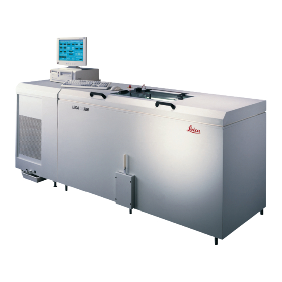
- Page 11 Characteristics of the Leica CM3600 XP Characteristics of the Leica CM3600 XP Layout of the Leica CM3600 XP Fig. 1 Commercially available computer with monitor, keyboard and mouse. Port and switch The port and switch panel contains the main power switch and several sockets and ports.
- Page 12 Knife (160 mm) with facet angle of: 20°, 35° Control unit The Leica CM3600 XP is equipped with a commercially available computer with monitor, keyboard and mouse. For further information, please refer to the manual of the PC. Operating system: Windows ®...
- Page 13 Characteristics of the Leica CM3600 XP Electrical connections 380 V / 50 Hz • Nominal supply voltages: 380 V AC ± 10 % • Nominal frequency: 50 Hz • Line voltage tolerance: ± 10 % • Power draw: 2400 VA • Automatic cutout:...
- Page 14 The user must wear hearing protection when using the extraction. Instrument parts The Leica CM3600 XP consists of a sliding microtome in a large-volume cryochamber. The instrument is designed for cryosectioning large specimens or for processing specimens with the so-called cryo-planing technique.
- Page 15 Once the desired specimen block height has been reached, those sections that will actually be used for further examination are collected manually via the knee lever. The Leica CM3600 XP is operated via PC and/or manually via the knee lever. All data entries are made via the PC.
- Page 16 Warning The protective devices located on the instrument and the accessories must not be removed or modified. Only qualified service personnel authorized by Leica may repair the instrument and access its internal components. Warnings The safety devices installed in this instrument by the manufacturer only constitute the basis for accident prevention.
- Page 17 • For safety reasons, we strongly advise against lifting the microtome (approx. 190 kg) from the cryochamber without appropriate lifting gear. Do not attempt to lift the microtome from the cyrochamber manually, even if several persons are there to help. Leica CM3600 XP...
- Page 18 Safety Safety features 3.3.1 Emergency stop switch The Leica CM3600 XP is equipped with an switch (→ Fig. 2-1) located on the cabinet to Emergency stop the left of the window. To activate the switch: Emergency stop Press the Emergency stop switch (→...
- Page 19 Safety 3.3.2 Knee lever Never leave the Leica CM3600 XP unattended when the knee lever (→ Fig. 3-1) is folded out to prevent the microtome from being set in motion accidentally. Warning Always swing the knee lever upwards before leaving the instrument.
- Page 20 (if the instrument can pass straight through the doorway, a width of 95 cm will be sufficient). The Leica CM3600 XP has a total length (refrigeration and control unit plus cabinet) of 2.70 m or 2.80 m including the connecting lines on the left side of the refrigeration and control unit, i. e. a minimum installation wall width of 2.90 m is required to install the instrument.
- Page 21 Site requirements Room requirements Installation wall, ideal dimensions (view from above) 1 LEICA CM3600 XP 2 approx. 3.5 m 3 0.5 m 4 approx. 2.7 m Fig. 6 5 approx. 0.8 m Note Room temperatures and humidity levels in excess of the recommendations above will affect the cryostat's cooling capacity and the lowest stated temperatures will not be reached.
- Page 22 Installation Installation Unpacking and installation Only duly trained personnel may unpack and install the Leica CM3600 XP. Please contact your local Leica sales organization for appropriate advice. Standard delivery Qty. Designation Order No. Leica CM3600 XP basic instrument 14 0417 33766...
- Page 23 Note Check the delivery carefully against the packing list, delivery note and your order. Should there be any deviations, please contact the Leica sales office handling your order or your Leica dealer. Port and switch panel Connection for computer (Ethernet)
- Page 24 Installation 5.3.1 Port and switch functions Connection for computer (→ Fig. 7-1) The Ethernet interface is the connection of the computer to the PLC (electronic control unit). (→ Fig. 7-2) Connection for footswitch Optionally, a foot switch can be connected for the purpose of section thickness documentation (GLP). Connection for compressed air (→...
- Page 25 Indicate function of the refrigerating sets. (→ Fig. 7-9) Automatic cutout Protects the refrigerating sets and all electronic components. 5.3.2 Fuses The Leica CM3600 XP is equipped with the following fuses: • GFCI switch • Automatic cutout • Fuse protecting the main power switch...
- Page 26 • Flip it upwards to switch it back on. Fig. 11 The Leica CM3600 XP is equipped with a commercially available computer with monitor, keyboard and mouse. For further information, please refer to the manual of the PC. Note If a computer is to be provided by the user, please request the required PC configuration in advance from your responsible Leica sales company.
- Page 27 (for additional information, refer to Chapter Main (→ p. 31 – 6.4 Main window)). Note After 5 failed registration attempts, access to the unit will be locked. Only an administrator can remove the lock, see (→ p. 41 – 6.5.2 Password management). Leica CM3600 XP...
- Page 28 Software Description of the window elements Title bar Toolbar Working area Status bar Fig. 13 The window interface is divided into several areas: Title bar Title bar (→ Fig. 13-1) displays information on the instrument name and software version number. Toolbar (→...
- Page 29 Working area In the (→ Fig. 13-3) all information and settings for operating the instrument are entered. Working area Display format may vary depending on the icon selected in the toolbar. Leica CM3600 XP...
- Page 30 Software Status bar Status bar (→ Fig. 13-4) displays the following information: • The currently registered user • Instrument name and software version number • Number of sections carried out so far • Name of laboratory Initialization Note To be able to work with the instrument, after completion of the start and log-in procedure the microtome must be initialized.
- Page 31 Automatic defrost Sledge speed Automatic dehydration Mode Knife movement Cutting window 6.4.1 Chamber temperature Displays actual or set chamber temperature. • See (→ p. 38 – 6.5.1 Parameter settings) on how to configure these settings. Fig. 17 Leica CM3600 XP...
- Page 32 Software 6.4.2 Time Displays real time and date. • See (→ p. 38 – 6.5.1 Parameter settings) on how to configure these settings. Fig. 18 6.4.3 Automatic defrost Displays start time of 1st or 2nd automatic defrost cycle. • See (→...
- Page 33 • Clicking on Start/Stop moves the knife holder so the selected set position. • When activated, this button will light up in green. • Clicking on this button once more stops the knife holder. Leica CM3600 XP...
- Page 34 Software Note • Once the knife holder has reached the upper limit position, both Knife up buttons blink in green color. • Once the knife holder has reached the lower limit position, both buttons blink in yellow Knife down color. • Once the target position has been reached, it can only be left by activating the knee lever, see (→...
- Page 35 (→ p. 30 – 6.3 Initialization). Displays current sectioning or return stroke speed in mm/s (millimeters per second). • To modify any of the settings, click on the corresponding value. Leica CM3600 XP...
- Page 36 Software Buttons prior to initialization Buttons after initialization Fig. 25 • Clicking on this button opens the window, see Init Safety check – initialisation (→ p. 30 – 6.3 Initialization). • Prior to initialization, the button blinks yellow. • After the initialization procedure has been completed, the color of the Init button will change from yellow to green.
- Page 37 0 - 450 mm for the right limit position can be set here. Parameter settings Clicking on Parameter settings icon opens the parameter settings window. Fig. 27 The working area of the parameter settings window is divided as follows: Parameter settings Initialization Password list Language selection Configuration Reference voltages Leica CM3600 XP...
- Page 38 Software 6.5.1 Parameter settings Different settings can be selected using the Parameter setting menu. Fig. 28 (→ Fig. 28-1) Set chamber temperature Click on this display to change the currently selected value. Temperature values from -30 to +1 °C are permitted.
- Page 39 • The duration of the dehydration depends on the number of sections, the section thickness and the type of tissue. To use this function efficiently, it is advisable to remove the section waste from the cryochamber before the start of the dehydration. Leica CM3600 XP...
- Page 40 Software Dehydration T-reduction (→ Fig. 28-11) Displays temperature reduction for dehydration. Click on this display to change the currently selected value. Values from 0 - 20 K can be selected. Section thickness (→ Fig. 28-12) Displays section thickness. Click on this display to change the currently selected value. Values from 0 - 200 μm can be selected.
- Page 41 • Double-clicking a line in the configuration display opens the dialog box User configuration (→ Fig. 34). • Administrators have full access to all application functions. Users do not have access to password management and to the configuration parameters in the window. Parameter setting Leica CM3600 XP...
- Page 42 Software Fig. 34 In the User configuration dialog box, the following settings can be selected: Displays the running number. No changes can be made in this field. Active Clicking on the checkbox sets the user status to Active. Only after this step can a user successfully register via the start and log-in procedure.
- Page 43 The text entered into the 8 input fields is copied into the dialog box for creating main studies and substudies. Each individual text can consist of up to 30 characters. The configuration of a main study or substudy is covered in Chapter (→ p. 56 – 6.10 Section documentation). Leica CM3600 XP...
- Page 44 Software Fig. 36 Measured values tab (→ Fig. 35-3) Selecting the measured values that are to be displayed in the window after Section documentation selecting a main study or substudy. The configuration of a main study or substudy is covered in Chapter (→...
- Page 45 • Clicking on the checkbox in the corresponding line activates bold print. Bold • Specific information can be entered during label printing for the output of predefined variables commencing with the special character "@". Leica CM3600 XP...
- Page 46 Software Fig. 39 Note • Repeating the variable wild card defines the length of the variable. The variable wild card @333, for example, will display the "target cryochamber temperature" with a length of 4 characters. • The "@" character represents one character. • Text variables are always printed left-justified, numbers right-justified.
- Page 47 Buttons 1 to 8 are inactive. Fig. 42 6.5.5 Language selection The flag buttons indicate the languages that can be selected. Clicking on one of the flag symbols changes the user interface to the corresponding language. Fig. 43 Leica CM3600 XP...
- Page 48 Fig. 44 Temperature curves Clicking the Temperature curves icon opens the window. Fig. 45 The window contains the following areas: Work space Diagram Note display is only for failure analysis by Leica service technicians. Temperature curves Version 6.7, Revision D...
- Page 49 The following check boxes can be activated/deactivated via a mouse click: T1 to 1 T2 to 2 T3 tv1 T4 tv Head I T5 tv2,I T6 tv2,II T7 tHg2 T8 Box Leica CM3600 XP...
- Page 50 Software 6.6.2 Diagram Fig. 47 The window contains the following areas: Temperature in degree Graphical representation of the 8 temperature centigrade on the y-axis measuring points attached to the instrument by colored-coded lines Time and date on the x-axis The diagram can be enlarged as follows: • Within the diagram, press and hold the left mouse button.
- Page 51 The working area is divided up as follows: Work space Event list Events list is a table displaying the events chronologically by date and time. In this list, all events concerning the program are saved. 6.7.1 Work space Fig. 49 Leica CM3600 XP...
- Page 52 Software Fig. 50 Clicking on this button opens the dialog box (→ Fig. 50). Filter Filter Here you can define a time filter limiting the event table display to one day, one week or one month. To set a filter, proceed as follows: • Select the desired time interval by clicking on one of the radio buttons Day, Week or Month.
- Page 53 Individual events messages will be displayed in the events list for a maximum of 90 days from the date when the event occurred. After that, the data will be saved into a text file, see (→ Fig. 38-6) (→ Fig. 38-7). Leica CM3600 XP...
- Page 54 Software Alarm list Click the icon to open the corresponding window. Alarm list Fig. 52 The working area is divided up as follows: Work space Alarm list Chronological display of the Alarm list as a table in order of date and time. In this list, all events concerning the program are saved.
- Page 55 Displays date and time when the registered user confirmed the alarm message, Confirmed (→ p. 54 – 6.8.1 Work space) User Name of the user who confirmed the alarm Message Displays alarm messages Displays the comment made on the corresponding alarm message Comment Leica CM3600 XP...
- Page 56 Software 6.8.3 Error messages: Meaning and troubleshooting Error code Error message Confirm elimination Error 01 Knife holder – limit position • Re-initialize instrument. If the problem recurs, call exceeded Service Technician. Limit position of sledge • Re-initialize instrument. If the problem recurs, call Error 02 exceeded Service Technician.
- Page 57 • If you click on a study, the studies protocol and the events table will be displayed on the right, see (→ p. 58 – 6.10.2 Studies protocol). • To save a main study, select it using the left mouse button and move it into the Saved folder. Leica CM3600 XP...
- Page 58 Software Note Saved main studies can no longer be edited. 6.10.2 Studies protocol By clicking on a main study in the tree diagram (→ Fig. 56), the following display will appear in the area: Studies protocol Fig. 57 The table is divided into the following columns: Running number automatically allocated by the application Date Date when the main study was created...
- Page 59 Knife holder position at the time the section was made Knife holder position Dehydration Time when dehydration started/finished Comments can be entered by the user Comment When clicking on a created substudy in the tree diagram, the following display will appear in the Studies protocol area: Leica CM3600 XP...
- Page 60 Software Fig. 60 The table is divided into the following columns: Displays the running event number automatically allocated by the application Displays date or time when the event occurred Date/Time User Displays the user who was logged in when the event occurred Event Displays the event message Red:...
- Page 61 Note The foot switch cannot be used without first activating the icon. Save Leica CM3600 XP...
- Page 62 Software 6.17 User log-in/log-out Clicking on the symbol logs off the user currently logged in. Clicking again causes the start- and-login window to appear, see (→ p. 28 – 6.2 Description of the window elements). Note Logging off does not automatically stop or delete the actions and settings initiated in the application. 6.18 Quitting the application Clicking the icon closes the application.
- Page 63 Operating the Leica CM3600 XP Operating the Leica CM3600 XP Note To ensure proper handling of the Leica CM3600 XP as well as use of the specimen stages and the specimen blocks themselves, we strongly recommend participating in Leica application training. Check list Note • The checklist below provides an overview on how to successfully operate the Leica CM3600 XP.
- Page 64 Operating the Leica CM3600 XP Setting the chamber temperature Proceed as follows: • Open the window in the software and adjust the cryochamber temperature to the Parameter setting target value, see (→ p. 38 – 6.5.1 Parameter settings). Specimen stages This chapter provides instructions on how to insert the specimen stages.
- Page 65 Operating the Leica CM3600 XP Warning • Prior to any work involving the knife or the microtome, or inside the cryochamber, activate the Emergency stop switch, see (→ p. 18 – 3.3.1 Emergency stop switch). • Prior to any work involving the knife or the microtome, or in the cryochamber, swing the knee lever upwards, see (→...
- Page 66 Operating the Leica CM3600 XP Fig. 66 Fig. 67 7.5.2 Inserting the specimen stage, non-orientable Required tools: • Allen key, size 6 Proceed as follows: • Use the knee lever to move the sledge to the right-side reversal position, see (→...
- Page 67 This chapter provides instructions on how to insert the knives. • Since there is a considerable risk of injury, the safety notes listed above must be observed. • Two types of knives can be used in the Leica CM3600 XP: Standard knife Disposable blade holder and blade Fig.
- Page 68 Operating the Leica CM3600 XP 7.6.1 Inserting standard knives To insert a standard knife, proceed as follows. Required tools: • Allen key, size 4 Proceed as follows: • Use the knee lever to move the sledge to the right-side reversal position, see (→...
- Page 69 Operating the Leica CM3600 XP 7.6.2 Inserting the disposable blade holder with disposable blade To insert the disposable blade holder with disposable blade proceed as described below. Required tools: • Allen key, size 4, • Allen key, size 2.5 Proceed as follows: • Use the knee lever to move the sledge to the left-side reversal position, see...
- Page 70 Operating the Leica CM3600 XP • Tighten the screws (→ Fig. 77-9) of the disposable blade holder (→ Fig. 76-3). • Loosen the screws (→ Fig. 76-1). • Align the disposable blade holder (→ Fig. 76-3) using the positioning tool (→...
- Page 71 Operating the Leica CM3600 XP Setting the trimming parameters Warning • For reasons of safety and accuracy, the maximum trimming thickness should not exceed 100 μm per section. • When trimming biological material (particularly bone), the section thickness should not exceed 50 μm.
- Page 72 Operating the Leica CM3600 XP 7.8.2 Collecting the sections Prior to removing a section, an appropriately sized piece of tape must be attached to the specimen block surface. When doing so, please comply with the following safety instructions: Warning • Wear safety gloves.
- Page 73 7.10 Manually shifting the knife holder for high specimens Note Specimens with a total height of 200 mm can be sectioned with the Leica CM3600 XP. For this purpose, however, the manual shifting of the knife holder is necessary. The individual steps are described in the following chapters.
- Page 74 Operating the Leica CM3600 XP 7.10.2 Knife holder description (→ Fig. 81) shows the knife holder in the 100 mm position of vertical height. • A groove (→ Fig. 83-2) in the support columns (→ Fig. 83-1) mark the 100 mm position. This...
- Page 75 Operating the Leica CM3600 XP 7.10.3 Knife holder height adjustment • To adjust the knife holder on the support columns (→ Fig. 83-1), first unscrew both clamping levers (→ Fig. 82-7) on the bottom side. • Afterwards, slightly unscrew the 4 knurled screws (→...
- Page 76 Operating the Leica CM3600 XP 7.10.5 Sectioning thick blocks • Move the support columns (→ Fig. 85-1) with the knife holder (by clicking Knife Up (→ Fig. 21-16), (→ Fig. 21-18)) into the uppermost position. • Position the knife holder with the upper edge...
- Page 77 Do not attempt to lift the microtome from the cyrochamber manually, even if several persons are there to help. • When removing the microtome (approx. 190 kg), a ceiling crane capable of carrying that weight should be available. Leica CM3600 XP...
- Page 78 Cleaning and Maintenance Required tools: • Allen key, size 6 Proceed as follows: • Observe the safety notes in Chapter (→ p. 16 – 3. Safety). • Switch off the instrument and unplug the power plug, see (→ p. 24 – 5.3.1 Port and switch functions).
- Page 79 Cleaning and Maintenance Maintenance Note • The instrument requires maintenance from Leica Service at an interval of once per year. • The pushbutton switch of the refrigeration must likewise be pressed at least once a year. 8.2.1 Oiling Note Be sure to check the oil level every day and before each sectioning procedure.
- Page 80 Cleaning and Maintenance 8.2.2 Defrosting Three defrost procedures are available: • Automatic defrost I • Automatic defrost II • Manual defrost Automatic defrost I This defrost cycle takes place automatically once every 24 hours. The defrost cycle itself is mandatory, i.
- Page 81 Embedding frame, 150 x 450 mm 14 0022 50127 Disposable blade system for large-surface cryosections Leica disposable blade holder 157 AR, for disposable blades, type H 45 L 14 0417 26152 1 dispenser with 10 H 45 L disposable blades, with special coating, 45°,...
- Page 82 Section collecting tape, 148 mm x 66 m 14 0417 39652 Microtome oils and grease Special oil PDP 38, 100 ml bottle for Leica CM3600 XP 14 0336 06099 Special oil PDP 38, 500 ml bottle for Leica CM3600 XP...
- Page 83 Leica sales organization or the organization from which you have purchased the contractual product shall apply exclusively. Service information If you are in need of technical customer support or spare parts, please contact your Leica representative or the Leica dealer where you purchased the instrument. Please provide the following information: • Model name and serial number of the instrument.
- Page 84 Please comply with the Cleaning and Maintenance chapter and the Decontamination Declaration at the end of these Instructions for Use for notes on cleaning the Leica CM3600 XP. The instrument can be contaminated when using biohazardous specimens. Thorough disinfecting is required before re-commissioning or disposal (e.
- Page 85 Decontamination Confirmation Decontamination Confirmation Any product that is to be returned to Leica Biosystems or serviced on site must be properly cleaned and decontaminated. The associated decontamination certificate template can be found on our website www.LeicaBiosystems.com in the product menu. This template must be used to enter all required data.
- Page 86 Note Version 6.7, Revision D...
- Page 88 Leica Biosystems Nussloch GmbH Heidelberger Str. 17 - 19 69226 Nussloch Germany Tel.: +49 - (0) 6224 - 143 0 Fax: +49 - (0) 6224 - 143 268 Web: www.LeicaBiosystems.com...
Need help?
Do you have a question about the CM3600 XP and is the answer not in the manual?
Questions and answers