Sign In
Upload
Download
Table of Contents
Contents
Add to my manuals
Delete from my manuals
Share
URL of this page:
HTML Link:
Bookmark this page
Add
Manual will be automatically added to "My Manuals"
Print this page
×
Bookmark added
×
Added to my manuals
Manuals
Brands
Bosch Manuals
Measuring Instruments
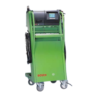
BEA 150
Repair instructions
Bosch BEA 150 Repair Instructions
Emissions analysis
Hide thumbs
1
Table Of Contents
2
3
4
5
6
7
8
9
10
11
12
13
14
15
16
17
18
19
20
21
22
23
24
25
26
27
28
29
30
31
32
33
34
35
36
37
38
39
40
41
42
43
44
45
46
47
48
49
50
51
52
53
54
55
56
57
58
59
60
61
62
63
64
65
66
67
68
69
70
71
72
73
74
75
76
77
78
79
80
81
82
83
84
85
86
87
88
89
90
91
92
93
94
95
96
97
98
99
100
101
102
103
page
of
103
Go
/
103
Contents
Table of Contents
Bookmarks
Table of Contents
Table of Contents
Important Information
1 Important Information
Compulsory Calibration
2 Testing Equipment and Settings for the Service Software
Testing Equipment
Calibrating Gases (with Manufacturer's Certificate)
Settings for the Service Software
Setting the Interface for the Service Program
Service Software Language Selection
Language Selection for RTM
Smoke Opacity Module Service Software
3 Brief Description of Unit Functions and Servicing the Unit
Exhaust-Gas Analyzer Module
Analyzer Part (HC, CO and CO 2 Measurement)
System Calibration
Self-Test
Adjustment
Measuring Channels)
Measuring Channel
Compensation of Pressure Influence
Compensation of Temperature Influence
Parameterization
Corrected CO Concentration
Filtration
Principle of Filtration
Servicing the Unit
Half-Yearly Service
Yearly Service
4 Checking the AMM Exhaust-Gas Analyzer Module
Read Operating Mode
Leakage Test
Read Measurement Values
Read Parameters
Write Parameters
Country-Specific Settings
Lambda Calculation on
Lambda Calculation off
Calculation on
CO Vrai
Sensor Available
Sensor Not Available
Identification
Test Functions
Pump on
Pump off
Install New O
Measurement
Readjustment with Test Gas
Analysis Mode
Barometric Sensor
Maintenance (Service Date)
Read Adjustment Data
Adjustment Functions
Reset
Error Inquiry
NO-Sensor
Read NO-Sensor
Set NO-Sensor
NO-Measurement
Mounting a New NO-Sensor
Readjustment with Test Gas
Read Calibration Data
Calibration Interval Setting
Calibration Sequence Setting
Checking Opacimeter RTM 430
5 Checking the PCB and Periphery of the BEA Control Module
Checking the Interface for DTM
Checking the Interface for RTM
Checking the Interface for AMM
Checking the Interface for OBD
Checking the Interface for OBD Extern
Loop Test
OBD Error Messages
Testing 26-Pin Interface for OBD External (with CAN Protocol)
Checking the Interface for the Data Terminal (Not for BEA-Euro)
Checking the Hard Disk
Checking the Floppy Disk Drive
Checking the Internal Printer
Checking the External Printer
Setting the Date and Time
Video RAM Test
Display Test
Display Test Geometry Image
Display Test Full Screen All White
Display Test Full Screen All Black
Checking the Foil Keypad
Checking the PC Keyboard
Checking the Remote Control
Checking the Test Calibration Switch for Customer Service
Reading out the Error List
Download Systemsoft
6 Checking the Engine-Speed and Temperature Measuring Module (DTM)
Checking Oil Temperature and Engine Speed in Diesel Diagnosis
Terminal Diagram of Connection Cable for
Terminal Diagram of Temperature Sensor
Checking Oil Temperature and Engine Speed in Petrol Diagnosis
Terminal Diagram of Inductive Clip-On Trigger Sensor
Checking V-Lambda
Terminal Diagram of V-Lambda Cable
Checking the Ignition Point and Dwell Angle
Checking the Dwell Angle
Terminal Diagram of Timing Light
Terminal Diagram of TD/TN Connection Cable
7 Technical Information
Exhaust-Gas Analysis in Petrol-Driven Vehicles
Opacity Measurement
Engine Measurement System TDM
Temperature Measurement
RPM Measurement, Petrol-Driven Vehicles
RPM Measurement, Diesel Vehicles
Multiple Measurements
Ignition Point/Timing
Dwell Angle
Start of Delivery/Injection Timing
8 Trouble-Shooting by Message Number
Explanations on Reference Numbers
General Messages
Messages about Boot Test Functions
Messages about Software Installation Functions
Messages about Printing Functions
Messages about Hardware Test Functions
Messages about Opacimeter RTM
Messages about EAM Exhaust-Gas Analyzer Module
Reference Numbers When Downloading DTM Firmware
Reference Messages on OBD Printed Circuit Board
Reference Numbers for Errors in "Fatal" Group
Reference Numbers for Errors in "Status Error" Group
Reference Numbers for Errors in "Download" Group
Reference Numbers for Errors in „Communication Error" Group
Reference Numbers in Combination with Awn.modul
Malfunction Messages for Testing OBD Printed Circuit Board with KTS115PC Program
Error Messages for "SDTEST
Error Messages for "DLCTEST
Error Messages for "LBCTEST
Error Messages for "CANTEST
9 Adjustment Functions
Setting the Maintenance Interval
Setting the Calibration Interval
Setting the Calibration Gas Components
Setting the Calibration Sequenz
Setting the Leakage Test Interval
Setting the HC Test
Setting CO
National Regulation Settings
Download
10 Repairs
Adjusting Mains Voltage for Toroidal Mains Transformer
AC / DC Voltage Supply to Control Module PCB
Block Circuit Diagram of Voltage Supply
View of Equipment Side of Control Module PCB
Visual Inspection of Measuring Bank of Exhaust-Gas Analyzer Module
Electrical Test of Measuring Bank of Exhaust-Gas Analyzer Module
Leak Test of Measuring Bank
Cleaning the Lamp Reflector
Cleaning the Analysis Chambers and Windows
Replacing the Measuring Bank
Install New O Sensor
Checking Cross Sensitivity
Checking the Pump Suction Power
Replacing the Pump
Checking the Pressure Sensor
Checking the Response Time of the Pressure Sensor
Replacing the Pressure Sensor
Replacing the Water Separator
Replacing the Solenoid Valve
Replacing the no Sensor
Replacing the Internal Printer
Replacing the Printing Mechanism
Replacing the Controller PCB
Replacing the Disk Drive
Replacing the TFT Display
Replacing the Membrane Keypad
Replacing the Receiver Diode for the Remote Control
Replacing the Control Module PCB
Replacing the Temperature and RPM PCB
Replacing the Control-Power Transformer
Replacing the OBD Circuit Board
Replacing AWN Printed Circuit Board
Replacing the Power Switch
Replacing the Battery
Replacing Hard Disc
11 BEA Test Software OS9
Hard Disk
Identification
Testing
Formatting
Flash
Floppy Disk
Language
12 Overview
Electrical Wiring (Siemens Analysis Chamber)
Circuit Diagram (Siemens Analysis Chamber)
Wiring Diagram (Siemens Analysis Chamber)
Hosing (Siemens Analysis Chamber)
Gas Circuit Diagram (Siemens Analysis Chamber)
Electrical Wiring (Andros Analysis Chamber)
Circuit Diagram (Andros Analysis Chamber)
Wiring Diagram (Andros Analysis Chamber)
Hosing (Andros Analysis Chamber)
Gas Circuit Diagram (Andros Analysis Chamber)
Overview of Components
Advertisement
Quick Links
Download this manual
Repair Instructions
Bosch Emissions Analysis
BEA 150
BEA 250
BEA 350
In conjunction with Service
software for PC
1
Table of
Contents
Previous
Page
Next
Page
1
2
3
4
5
Advertisement
Table of Contents
Need help?
Do you have a question about the BEA 150 and is the answer not in the manual?
Ask a question
Questions and answers
Related Manuals for Bosch BEA 150
Measuring Instruments Bosch BEA 060 Original Instructions Manual
(56 pages)
Measuring Instruments Bosch BEA 550 Original Instructions Manual
(101 pages)
Measuring Instruments Bosch BEA 060 Original Instructions Manual
Exhaust gas analyzer for gasoline vehicle (306 pages)
Measuring Instruments Bosch BEA 070 Original Instructions Manual
Opacimeter (52 pages)
Measuring Instruments Bosch BEA 070 Original Instructions Manual
Opacimeter (268 pages)
Measuring Instruments Bosch BEA 750 Original Instructions Manual
(300 pages)
Measuring Instruments Bosch BEA 810 Servicing Instructions
Emissions analysis (18 pages)
Measuring Instruments Bosch BEA 040 Original Instructions Manual
Speed measurement module (196 pages)
Measuring Instruments Bosch BEA 250 Repair Instructions
Emissions analysis (103 pages)
Measuring Instruments Bosch BEA 350 Repair Instructions
Emissions analysis (103 pages)
Measuring Instruments Bosch BEA 460 Product Description
Bosch-emissions-analyzer (168 pages)
Measuring Instruments Bosch BEA 055 Original Instructions Manual
Exhaust gas analyzer for gasoline vehicle (280 pages)
Measuring Instruments Bosch BEA 055 Original Instructions Manual
Exhaust gas analyzer for gasoline vehicle (280 pages)
Measuring Instruments Bosch BEA 055 Original Instructions Manual
Exhaust gas analyzer for gasoline vehicle (184 pages)
Measuring Instruments Bosch BEA 065 (UNI) Original Instructions Manual
Emissions analysis (318 pages)
Measuring Instruments Bosch BL 40 VHR Operating Instructions Manual
(22 pages)
This manual is also suitable for:
Bea 250
Bea 350
Table of Contents
Save PDF
Print
Rename the bookmark
Delete bookmark?
Delete from my manuals?
Login
Sign In
OR
Sign in with Facebook
Sign in with Google
Upload manual
Upload from disk
Upload from URL


Need help?
Do you have a question about the BEA 150 and is the answer not in the manual?
Questions and answers