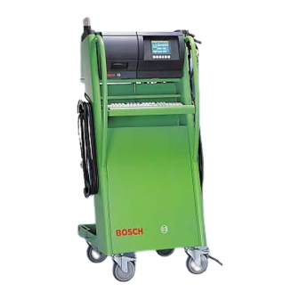
Summarization of Contents
Important Information and Calibration Requirements
Compulsory Calibration Regulations
Adherence to country-specific regulations for exhaust-gas analyzer calibration.
Testing Equipment and Service Software Setup
Required Testing Equipment
Lists essential hardware and software for testing the unit.
Calibrating Gases Specifications
Details required calibrating gases and their certificates for accuracy.
Service Software Configuration
Setting up the service program interface and language.
AMM Exhaust-Gas Analyzer Module Functions
Reading Operating Mode and Leakage Tests
Displaying current status and performing manual leak tightness checks.
Measurement and Parameter Reading
Accessing current measurement values and set parameters.
Parameter Writing and Country-Specific Settings
Entering country-specific parameters for operation.
Lambda and COvrai Calculation Control
Enabling or disabling lambda and corrected CO calculations.
O2 Sensor Configuration
Setting the module for O2 sensor availability or non-availability.
Entering Lambda Coefficients
Inputting fuel-specific OCV and HCV coefficients for lambda calculation.
Module Identification and Test Functions
Viewing software version and accessing diagnostic tests.
Pump and O2 Sensor Functions
Testing pump operation and O2 sensor measurements.
Test Gas Readjustment and Analysis Mode
Recalibrating with test gas and using analysis mode.
Maintenance Confirmation and Data Reading
Confirming maintenance and reading adjustment data.
Adjustment Functions, Reset, and Error Inquiry
Accessing adjustments, resetting module, and checking errors.
NO Sensor Monitoring and Calibration
Managing NO sensor status, installation, measurement, and recalibration.
Opacimeter RTM 430 Checking
Procedure for checking the RTM 430 opacimeter via service software.
PCB and Periphery Checks
Interface Checks for DTM, RTM, and AMM
Testing communication interfaces for DTM, RTM, and AMM modules.
OBD Interface Testing
Checking OBD and external OBD interfaces, including error messages.
Internal Component Functionality Tests
Testing hard disk, floppy disk drive, and printers.
Display and Input Device Tests
Testing TFT display, keypads, keyboards, and remote control.
Error List and System Software Download
Reading error lists and downloading system software.
System Software Version Information
Retrieving current system software versions for modules.
Engine-Speed and Temperature Module (DTM) Checks
Diesel Diagnosis: Oil Temp & Engine Speed
Checking oil temperature and engine speed in Diesel diagnosis mode.
Petrol Diagnosis: Oil Temp & Engine Speed
Checking oil temperature and engine speed in Petrol diagnosis mode.
V-Lambda Voltage Test
Performing the V-lambda voltage test with connection cable.
Ignition Point and Dwell Angle Checks
Testing ignition point and dwell angle with specific cables.
Dwell Angle Measurement
Measuring dwell angle in percentage, milliseconds, or degrees.
Technical Information and Troubleshooting
Exhaust-Gas Analysis Technical Data
Measuring ranges, resolution, and tolerances for exhaust-gas components.
Opacity Measurement Specifications
Technical data for opacity measurement and absorption coefficient.
Engine Measurement System TDM+ Specs
Technical details for temperature and RPM measurements.
Troubleshooting by Message Number
Guide to troubleshooting based on displayed malfunction messages.
Error Messages: Boot Test and Software Installation
Handling errors related to boot tests and software installation.
Error Messages: Printing, Hardware, and RTM 430
Troubleshooting printing, hardware, and opacimeter errors.
Error Messages: EAM, DTM Firmware, and OBD PCB
Error codes for EAM module, DTM firmware, and OBD PCB issues.
OBD PCB Malfunction Messages
Specific error messages for OBD PCB testing (SDTEST, DLCTEST).
Adjustment Functions and Software Downloads
Setting Maintenance and Calibration Intervals
Configuring intervals for unit maintenance and gas recalibration.
Calibration Gas Components and Sequence
Defining gas channels for recalibration and reaction to interval expiry.
Leakage Test, HC Test, and COvrai Settings
Configuring leakage test frequency, HC test, and COvrai setting.
National Regulation Settings and Software Download
Setting country-specific parameters and downloading new software.
Repairs and Component Replacement
Mains Voltage Adjustment and PCB Voltage Supplies
Checking and adjusting mains voltage and PCB voltage supplies.
Voltage Supply Block Diagram and PCB View
Schematics of voltage supply and layout of control module PCB.
Measuring Bank Inspection and Electrical Tests
Visually inspecting and electrically testing the measuring bank.
Cleaning Lamp Reflector and Analysis Chambers
Procedures for cleaning the lamp reflector and analysis chambers.
Replacing Core Components
Guides for replacing measuring bank, O2 sensor, pump, and water separator.
Component Replacement Procedures
Instructions for replacing pressure sensor, solenoid valve, and NO sensor.
Printer, Disk Drive, and Display Replacements
Steps for replacing internal printer, disk drive, and TFT display.
PCB, Switch, Battery, and Hard Disk Replacements
Procedures for replacing PCBs, power switch, battery, and hard disk.
OBD and AWN Circuit Board Replacement
Instructions for replacing OBD and AWN printed circuit boards.
BEA Test Software and System Overview
Hard Disk Testing and Formatting
Testing and formatting the hard disk using BEA test software.
Floppy Disk and Language Settings
Testing the floppy disk drive and selecting software language.
System Wiring and Circuit Diagrams
Electrical wiring, circuit, and hosing diagrams for analysis chambers.
Component Overview Schematic
Schematic showing the arrangement of major system components.


Need help?
Do you have a question about the BEA 350 and is the answer not in the manual?
Questions and answers