Table of Contents
Advertisement
Quick Links
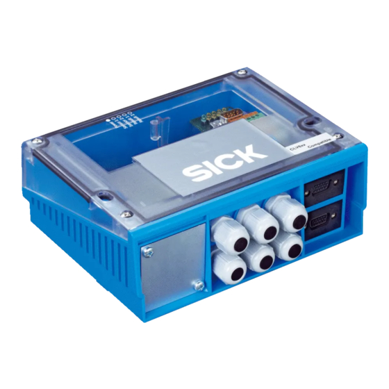
C D M 4 2 0 - 0 0 0 4
A n s c h l u s s m o d u l
Connection Module
B e t r i e b s a n l e i t u n g
1. Produkteigenschaften
Modular aufgebautes Anschlussmodul zum Anschluss einer Ein-
■
heit von zwei SICK 1D/2D-Codelesern an Host, CAN-Scanner-
Netzwerk, Feldbussysteme und an Peripherie u. Stromversorgung
Unterstützte 1D/2D-Codeleser: Barcodescanner CLV42x ... 45x,
■
CLV6xx sowie Image Code Reader ICR84x-2, ICR85x-2
Basisgerät CDM420-0004 zur optionalen Aufnahme
■
- eines Cloning-Moduls CMC400/CMC600 für externe Speiche-
rung der Konfigurationsparameter für 1D/2D-Codeleser 1
- eines Display-Moduls CMD400 im optionalen Deckel zur An-
zeige von Leseergebnissen und Lesediagnosedaten des 1D/
2D-Codelesers 1 (Modul nicht anwendbar zusammen mit
Power-Supply-Modul CMP490)
- von Feldbus-Modulen CMF400 zur Anbindung des 1D/2D-
Codelesers 1 an PROFBUS-DP, DeviceNet oder Ethernet TCP/IP
Für 1D/2D-Codeleser 1 über CMC600:
■
zusätzlich zwei Schalteingänge für CLV 42x ... 45x und CLV6xx
sowie zusätzlich zwei Schaltausgänge für CLV6xx
Zwei 9-pol. D-Sub-Stecker intern, für Anschluss der seriellen Aux-
■
Schnittstellen (RS-232) an PC zur Konfiguration/Diagnose der
1D/2D-Codeleser
Variante CDM420-0004S01, zusätzlich:
■
- Power-Supply-Modul CMP490 im optionalen Deckel zur Span-
nungsversorgung der beiden 1D/2D-Codeleser aus einem
Wechselstromnetz
- Serielle Aux-Schnittstellen der 1D/2D-Codeleser zusätzlich
über zwei 9-polige D-Sub-Buchsen auf Frontblende
Klemmen für Host-Schnittstelle, CAN-Bus, Schaltein- und
■
-ausgänge, Stromversorgung, Schirmung
Anschluss der 1D/2D-Codeleser über zwei 15-polige D-Sub-HD-
■
Stecker, Peripherie über Kabelverschraubungen, Feldbus über
systemabhängige Steckverbindungen (Frontblende)
Von außen sichtbar: LEDs zur Anzeige von aktiven Schaltein- und
■
ausgängen sowie Schalterstellungen der Modulkonfiguration
Schutzart IP 65 (Variante CDM420-0004S01: IP 20)
■
Wartungsfrei
■
UL-zertifiziert bei Verwendung eines Class 2-Netzgeräts
■
(geprüft nach UL 1310) zur Stromversorgung
Weitere Produktinformationen, Programm „CLV-Connect":
Siehe www.sick.com
8011155/S012/2009-04
1D/2D
1D/2D
Code
Code
Reader
Reader
Lichtschranke
(Lesetakt)
Photo reflex
"Sensor 1"
switch
(Reading clock)
"Sensor 2"
Schalter/switch
Teach-in matchcode
O p e r a t i n g I n s t r u c t i o n s
1. Features
Compact connection module for connecting a unit of two SICK
■
1D/2D code readers to the host, CAN scanner network, field bus
systems, and to the peripheral equipment and power supply
Supported 1D/2D code readers: bar code scanner CLV42x to
■
45x, CLV6xx or image code reader ICR84x-2, ICR85x-2
Basic device CDM420-0004 for integrating optionally the
■
- CMC400/CMC600 cloning module for saving the 1D/2D code
reader's 1 configuration parameters externally
- CMD400 display module (installed in a cover variant) for
displaying the reading results and reading diagnosis data of
the 1D/2D code reader 1 (not applicable together with the
CMP490 power supply module)
- CMF400 field bus modules for connecting the 1D/2D code
reader 1 to the PROFBUS-DP, DeviceNet or Ethernet TCP/IP
For 1D/2D code reader 1 via CMC600:
■
additionally two switching inputs for CLV 42x to 45x and CLV6xx
as well as two switching outputs for CLV6xx
Two 9-pin internal D-Sub connectors, for connecting the serials
■
Aux interfaces (RS 232) to a PC for configuring/diagnosing the
1D/2D code readers
CDM420-0004S01 version, additionally:
■
- CMP490 power supply module in optional cover for supplying
power from an AC power line
- Serials Aux interfaces can also be connected via two 9-pin D-
Sub sockets on face plate (front)
Terminals for host interface, CAN bus, switching inputs/outputs,
■
power supply, and shield
Connection of the 1D/2D code readers via two 15-pin D-Sub HD
■
plugs, peripheral equipment via cable glands, and field bus via
system depending plug-in connections on face plate (front)
Externally visible LEDs for displaying active switching inputs and
■
outputs, as well as switch settings for module configuration
Enclosure rating IP 65 (CDM420-0004S01 version: IP 20)
■
Maintenance-free
■
UL certificated when a class 2 power supply according to
■
UL 1310 is used
Further Product Information, "CLV-Connect" PC Program:
See www.sick.com
© SICK AG · Division Auto Ident · Germany · All rights reserved
"Aux"
"CAN"
CDM420-0004
"Host"
"Result 1"
"Result 2"
2 x
"Result 1"
"Result 2"
2 x
V
S
PC
CAN bus
HOST
(Reader 1)
SPS/
PLC
(Reader 2)
1 # 8
Advertisement
Table of Contents

Related Manuals for SICK CDM420-0004


Summary of Contents for SICK CDM420-0004
- Page 1 UL 1310 is used ■ (geprüft nach UL 1310) zur Stromversorgung Weitere Produktinformationen, Programm „CLV-Connect“: Further Product Information, ”CLV-Connect” PC Program: Siehe www.sick.com See www.sick.com 8011155/S012/2009-04 © SICK AG · Division Auto Ident · Germany · All rights reserved 1 # 8...
-
Page 2: Eg-Konformitätserklärung
*) nur für 1D/2D-Codeleser 1 Note: simultaneous operation of CMD400 Display Module and CMP490 Power Supply Module not possible. for 1D/2D code reader 1 only 2 # 8 © SICK AG · Division Auto Ident · Germany · All rights reserved 8011155/S012/2009-04... -
Page 3: Elektrische Installation
10 to 30 V DC / 18 to 30 V DC ICR84x-2 DC 15 ... 30 V ICR84x-2 15 to 30 V DC 8011155/S012/2009-04 © SICK AG · Division Auto Ident · Germany · All rights reserved 3 # 8... - Page 4 3. CAN-Bus: Falls CDM420 am Busende, Terminierungswiderstand 3. CAN bus: if CDM420 is integrated at bus end, enable termination mit Schalter S 4 zuschalten. resistor with switch S 4. 4 # 8 © SICK AG · Division Auto Ident · Germany · All rights reserved 8011155/S012/2009-04...
-
Page 5: Technische Daten
1) Operating temperature 0 to +40 °C (+32 to +104 °F) 3) nicht für CDM420-0004S01 2) only for 1D/2D code reader 1 3) not for CDM420-0004S01 8011155/S012/2009-04 © SICK AG · Division Auto Ident · Germany · All rights reserved 5 # 8... - Page 6 Erforderlicher Anschlussraum für Stecker Space required for connecting plug Erforderlicher Anschlussraum für Stecker bei optionaler Blende Space required for connecting plugs when using optional face plate 6 # 8 © SICK AG · Division Auto Ident · Germany · All rights reserved 8011155/S012/2009-04...
- Page 7 Stromlaufplan Anschlusskarte 1 (1D/2D-Codeleser 1)/circuit diagram of connecting board 1 (1D/2D code reader 1) 8011155/S012/2009-04 © SICK AG · Division Auto Ident · Germany · All rights reserved 7 # 8...
- Page 8 1D/2D code reader Codeleser 1D/2D code reader connection 1D/2D code reader connection Reader 1 Reader 2 SICK AG · Waldkirch · Germany · www.sick.com 8 # 8 © SICK AG · Division Auto Ident · Germany · All rights reserved 8011155/S012/2009-04...
Need help?
Do you have a question about the CDM420-0004 and is the answer not in the manual?
Questions and answers