
Related Manuals for Invertek Drives OPTIDRIVE E3 Series


Summary of Contents for Invertek Drives OPTIDRIVE E3 Series
- Page 1 AC Variable Speed Drive IP66 (NEMA 4X) 0.37kW – 22kW / 0.5HP – 30HP 1 10V & 230V Single Phase input, 230V & 480V 3 Phase input Switched Non-switched...
-
Page 2: Identifying The Drive By Model Number
CHECK: Check the correct drive type, check suitable Please scan the QR code motor type & info to access the complete PREPARE: Correct tools, suitable mounting location, User Manual weather protection MOUNT: Mechanical mounting CONNECT: Power & Control connections CHECK: Final check of everything before operation POWER ON COMMISSION the drive parameters Or visit bit.ly/E3manuals... -
Page 3: Mechanical Dimensions
3 MOUNT Mechanical Dimensions Dimensions Weight Weight Drive Drive Size Size 232.0 9. 1 3 189.0 7.44 25.0 0.98 162.0 6.37 161.0 6.34 257.0 10. 1 2 200.0 7.87 28.5 1. 1 2 182.0 7. 1 6 188.0 7.40 310.0 12.20 251.5 9.90... -
Page 4: Cable Selection
4 CONNECT Cable Selection F or 1 phase supply (Sizes 1-3 only), the mains power cables should be connected to L1/L, L2/N. F or 3 phase supplies, the mains power cables should be connected to L1, L2, and L3. Phase sequence is not important. F or compliance with CE and C Tick EMC requirements, refer to online documentation. -
Page 5: Control Terminal Wiring
Information for UL Compliance Optidrive E3 is designed to meet the UL requirements. For an up to date list of UL compliant products, please refer to UL listing NMMS.E226333. In order to ensure full compliance, the following must be fully observed. Input Power Supply Requirements Supply Voltage 200 –... -
Page 6: Motor Thermistor Connection
Switched Units: Default functions of the control switches Switch Position Notes Factory Default Configuration. Run Forward or Reverse with speed controlled from the Local POT. Sets the output frequency Run Reverse STOP Run Forward NOTE Other functions are possible, please refer to the online documentation for additional information. Using the Control Terminals Connection Example Purpose... -
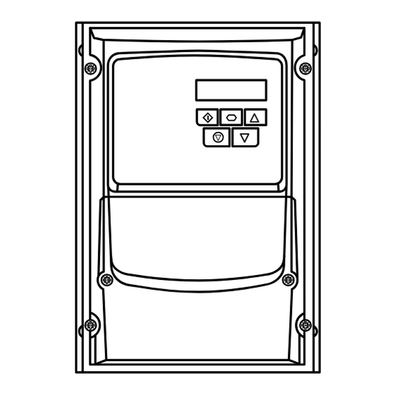
Page 7: Operation
6 POWER ON 7 COMMISSION Operation Managing the Keypad Used to decrease speed in real-time The drive is configured and its operation monitored via the DOWN mode or to decrease parameter values keypad and display. in parameter edit mode. When in keypad mode, used to Start a Used to display real-time information, stopped drive or to reverse the direction START... -
Page 8: Standard Parameters
8 OPERATE Parameters Standard Parameters Par. Description Default Units P-01 Maximum Frequency/Speed Limit P-02 500.0 50.0 (60.0) Hz/RPM P-02 Minimum Frequency/Speed Limit P-01 Hz/RPM P-03 Acceleration Ramp Time 0.00 600.0 P-04 Deceleration Ramp Time 0.00 600.0 P-05 Stopping Mode/Mains Loss Response Setting On Disable On Mains Loss... -
Page 9: Extended Parameters
Extended Parameters Par. Description Default Units P-15 Digital Input Function Select P-16 Analog Input 1 Signal Format See Below U0-10 U : Unidirectional, External 0 – 10Volt reference / pot 4 : External 20 – 4mA signal, trip on loss B ... -
Page 10: Advanced Parameters
Par. Description Default Units P-43 PI Controller Operating Mode 0: Direct Operation 2: Direct Operation, Wake at Full Speed 1: Inverse Operation 3: Reverse Operation, Wake at Full Speed P-44 PI Reference (Setpoint) Source Select 0: Digital Preset Setpoint 1: Analog Input 1 Setpoint P-45 PI Digital Setpoint 100.0... - Page 11 Technical Data Environment Operational ambient temperature range Enclosed Drives: -20 ... 40°C (frost and condensation free) Storage ambient temperature range: -40 … 60°C Maximum altitude: 2000m. Derate above 1000m: 1% / 100m Maximum humidity: 95%, non-condensing Rating Tables Frame Input Fuse/MCB Maximum Cable Output...
-
Page 12: Troubleshooting
NOTE Following an over current or overload trip (1, 3, 4, 15), the drive may not be reset until the reset time delay has elapsed to prevent damage to the drive. Ñ82-E3I66-IN_V1.05JÓ 82-E3I66-IN_V1.05 Invertek Drives Ltd. Offa's Dyke Business Park, Welshpool, Powys SY21 8JF United Kingdom Tel: +44 (0)1938 556868 Fax: +44 (0)1938 556869 www.invertekdrives.com...
Need help?
Do you have a question about the OPTIDRIVE E3 Series and is the answer not in the manual?
Questions and answers