Table of Contents
Advertisement
Available languages
Available languages
Quick Links
Advertisement
Chapters
Table of Contents

Related Manuals for ProLights PANORAMAIPSPOT


Summary of Contents for ProLights PANORAMAIPSPOT
- Page 1 PANORAMAIPSPOT HYBRID MOVING USER MANUAL MANUALE UTENTE EN - IT...
- Page 2 All rights reserved by Music & Lights S.r.l. No part of this instruction manual may be reproduced in any form or by any means for any commercial use. In order to improve the quality of products, Music&Lights S.r.l. reserves the right to modify the characteristics stated in this instruction manual at any time and without prior notice.
-
Page 3: Table Of Contents
3. 12 Information 3. 13 Automatic Mode 4 Maintenance 4. 1 Maintenance and cleaning the unit 4. 2 Trouble shooting • PANORAMAIPSPOT Packing content • Mount bracket • Power supply cable and signal cable • Safety rope • User manual... -
Page 4: General Instructions
PANORAMAIPSPOT WARNING! Before carrying out any operations with the unit, carefully read this instruction manual and keep it with cure for future reference. It contains important information about the installation, usage and maintenance of the unit. SAFETY General instruction • The products referred to in this manual conform to the European Community Directives and are there- fore marked with . -
Page 5: Introduction
PANORAMAIPSPOT - 1 - INTRODUCTION 1.1 TECHNICAL SPECIFICATIONS LIGHT SOURCE • Source: 420W high-power white LED • CT: 7000K • Lux: (5°) 21362lux @5m • Lux: (50°) 1173lux @5m full • Source life expectancy: >20.000 h OPTICS • Zoom: 5-50° motorised linear zoom •... - Page 6 PANORAMAIPSPOT • Strobe / shutter: 1/28 Hz, electronic • Battery backup: battery backup for user operation without connecting to the main power • Operating temperature: -20° ~ +45° ELECTRICAL • Power supply: 100-240V – 50/60Hz • Power consumption (at 230V): 492W •...
- Page 7 PANORAMAIPSPOT 474,4 Technical drawing Fig.1...
-
Page 8: Operating Elements And Connections
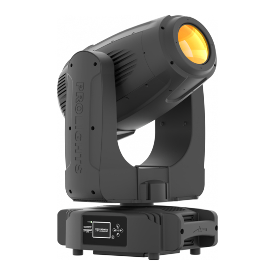
PANORAMAIPSPOT 1.2 OPERATING ELEMENTS AND CONNECTIONS 1. MOVING HEAD 2. ROTARY ARM 3. HANDLE 4. CONTROL PANEL with LCD display and 5 button used to access the control panel functions and manage them. 5. LED INDICATOR "W-DMX" 6. LED INDICATOR POWER 7. -
Page 9: Installation
2.1 MOUNTING The PANORAMAIPSPOT may be set up on a solid and even surface. By means of the fixing facilities of the baseplate, the unit can also be mounted upside down to a cross arm. The base plate is shown in fig.3. For fixing, stable mounting clips are required. -
Page 10: Functions And Settings
3.2 BASIC The PANORAMAIPSPOT has a LCD display and 5 button used to access the control panel functions and manage them (fig.4). -
Page 11: Menu Structure
PANORAMAIPSPOT 3.3 MENU STRUCTURE MENU ð ð ð CONNECT Address Value (1-512) ð W-DMX Value (1-512) ð Artnet Value (1-512) Standard; Extended; Basic-8bit; Basic-16bit; ð ð DMX Mode Mode Extended-16bit; User; ð Edit User Max Channel=XX / PAN= CH01 ð... - Page 12 PANORAMAIPSPOT ð ð ADVANCED Reset Pan & Tilt Others ð ð Calibration Password 050 (unlocks the following settings) ð Value Others ð ð Reload Default Basic Reload ON/OFF ð Program Reload ON/OFF ð Password 050 (unlocks the following settings) ð...
-
Page 13: Connect
• Press the LEFT button repeatedly to exit the menu and save changes. DMX MODE The PANORAMAIPSPOT has 5 DMX channel configurations which can be accessed from the control panel. • Press the ENTER button to access the main menu. -
Page 14: Rdm
DMX channel. If e. g. address 33 on the controller is provided for controlling the function of the first DMX channel, adjust the start address 33 on the PANORAMAIPSPOT. The other functions of the light effect panel are then automatically assigned to the following addresses. -
Page 15: Connection Of The Dmx Line
PANORAMAIPSPOT 3.6 CONNECTION OF THE DMX LINE DMX connection employs standard XLR connectors. Use shielded pair-twisted cables with 120Ω imped- ance and low capacity. The following diagram shows the connection mode: DMX - INPUT DMX - OUTPUT XLR plug XLR socket... -
Page 16: Dmx Channel
PANORAMAIPSPOT 3.8 DMX CHANNELS BAS-8 BAS-16 EXT2 FUNCTION Value 28 Ch 29 Ch 19 Ch 21 Ch 36 Ch 0~100% 000 - 255 PAN FINE 0~100% 000 - 255 TILT 0~100% 000 - 255 TILT FINE 0~100% 000 - 255... - Page 17 PANORAMAIPSPOT BAS-8 BAS-16 EXT2 FUNCTION Value 28 Ch 29 Ch 19 Ch 21 Ch 36 Ch No function (shutter open) 096 - 127 Pulse-effect in sequences 128 - 159 No function (shutter open) 160 - 191 Random strobe effect slow to fast...
- Page 18 PANORAMAIPSPOT BAS-8 BAS-16 EXT2 FUNCTION Value 28 Ch 29 Ch 19 Ch 21 Ch 36 Ch COLOR Indexed 1 - Open 000 - 002 2 - Open / Dark Red 003 - 005 3 - Dark Red 006 - 008...
- Page 19 PANORAMAIPSPOT BAS-8 BAS-16 EXT2 FUNCTION Value 28 Ch 29 Ch 19 Ch 21 Ch 36 Ch Forward Wheel Spin Stop to fastest 224 - 239 Reverse Wheel Spin Stop to fastest 240 - 255 CYAN 0~100% 000 - 255 CYAN FINE...
- Page 20 PANORAMAIPSPOT BAS-8 BAS-16 EXT2 FUNCTION Value 28 Ch 29 Ch 19 Ch 21 Ch 36 Ch ROTATING GOBO Indexed Open 000 - 005 Gobo 1 006- 011 Gobo 2 012- 017 Gobo 3 018 - 023 Gobo 4 024 - 029...
- Page 21 PANORAMAIPSPOT BAS-8 BAS-16 EXT2 FUNCTION Value 28 Ch 29 Ch 19 Ch 21 Ch 36 Ch GOBO ROTATION Continuous Positioning from 0-360 degrees 000 - 191 Forward Animate Rotate Stop to fastest 192- 207 Reverse Animate Rotate Stop to fastest...
- Page 22 PANORAMAIPSPOT BAS-8 BAS-16 EXT2 FUNCTION Value 28 Ch 29 Ch 19 Ch 21 Ch 36 Ch FIXED GOBO Indexed 000 - 006 Open Gobo 1 007 - 013 014 - 020 Gobo 2 Gobo 3 021 - 027 028 - 034...
- Page 23 PANORAMAIPSPOT BAS-8 BAS-16 EXT2 FUNCTION Value 28 Ch 29 Ch 19 Ch 21 Ch 36 Ch FOCUS Continuous Focus IN to Focus OUT 000 - 255 Auto Focus Focus adjustment 000 - 255 FOCUS FINE Focus Fine ZOOM Small to big...
-
Page 24: Gobos
PANORAMAIPSPOT 3.9 COLOR WHEELS - GOBOS COLOR WHEEL COLOR 1 COLOR 2 COLOR 3 COLOR 4 COLOR 5 COLOR 6 COLOR 7 COLOR 8 ROTATING GOBOS WHEEL GOBO 1 GOBO 2 GOBO 3 GOBO 4 GOBO 5 GOBO 6 GOBO 7... -
Page 25: Setup
PANORAMAIPSPOT 3.10 SETUP You can change the parameters for the device by following these steps: TEMPERATURE You can change the parameters of the device by following these steps: • Press the ENTER button to access the main menu. • Press the UP/DOWN button to scroll the menu, select the Set Up icon, then press the ENTER button to enter the next menu. -
Page 26: Advanced
• FIXTURE For the PANORAMAIPSPOT you can access the following special functions: • Press the ENTER button to access the main menu. • Press the UP/DOWN button to scroll the menu, select the icon Set Up, then press the ENTER button to enter the next menu. -
Page 27: Information
PANORAMAIPSPOT Calibration Select this function to calibrate and adjust the wheels of the effects in their correct positions: • Press the ENTER button to access the main menu. • Press the UP/DOWN button keys to scroll the menu, select the Set icon, then press the ENTER button to enter the next menu. -
Page 28: Automatic Mode
PANORAMAIPSPOT 3.13 OPERATIONS IN AUTOMATIC MODE The unit independently runs through its show. Before you send an automatic program you need to set the drive as Master/Alone: • Press the ENTER button to access the main menu. • Press the UP/DOWN button to scroll the menu, select the Stand Alone icon, then press the ENTER button to enter the next menu. - Page 29 • Press the LEFT button repeatedly to exit the menu and save changes. Select the desired program on the master unit (described in section 3.5). Use the DMX connectors of the PANORAMAIPSPOT and an XLR cable to form a chain of units. SCENES RECORD MODE PANORAMAIPSPOT is equipped with a built-in DMX recorder by which you can transmit the programmed scenes from your DMX-controller to the device.
- Page 30 PANORAMAIPSPOT the bass range. If the music control should not work optimally, increase the volume or reduce the distance between the sound source and the light effect unit or alternatively increase the sensitivity of the micro- phone. • Press the ENTER button to access the main menu.
-
Page 31: Maintenance
PANORAMAIPSPOT - 4 - MAINTENANCE 4.1 MAINTENANCE AND CLEANING THE UNIT • Make sure the area below the installation place is free from unwanted persons during setup. • Switch off the unit, unplug the main cable and wait until the unit has cooled down. -
Page 32: Troubleshooting
PANORAMAIPSPOT 4.2 TROUBLESHOOTING Problems Possible causes Checks and remedies No mains supply Check the power supply voltage • • Dimmer fader set to 0 Increase the value of the dimmer channels • • All color faders set to 0 Increase the value of the color channels •... - Page 33 Note...
- Page 34 PANORAMAIPSPOT Music & Lights S.r.l. si riserva ogni diritto di elaborazione in qualsiasi forma delle presenti istruzioni per l’uso. La riproduzione - anche parziale - per propri scopi commerciali è vietata. Al fine di migliorare la qualità dei prodotti, la Music&Lights S.r.l. si riserva la facoltà di modificare, in qualunque momento e senza preavviso, le specifiche menzionate nel presente manuale di istruzioni.
- Page 35 3. 12 Informazioni sul dispositivo 3. 13 Operazioni in modalità automatica 4 Manutenzione 4. 1 Manutenzione e pulizia del sistema ottico 4. 2 Risoluzione dei problemi • PANORAMAIPSPOT Contenuto dell'imballo: • Staffa di fissaggio • Cavo di segnale e alimentazione • Cavo di sicurezza...
-
Page 36: Sicurezza
PANORAMAIPSPOT ATTENZIONE! Prima di effettuare qualsiasi operazione con l’unità, leggere con attenzione questo manuale e conservarlo accuratamente per riferimenti futuri. Contiene informazioni importanti riguardo l’installazione, l’uso e la manutenzione dell’unità. SICUREZZA Avvertenze generali • I prodotti a cui questo manuale si riferisce sono conformi alle Direttive della Comunità Europea e per- tanto recano la sigla . -
Page 37: Introduzione
PANORAMAIPSPOT - 1 - INTRODUZIONE 1.1 SPECIFICHE TECNICHE SORGENTE LUMINOSA • Sorgente: 420W LED bianco ad alta potenza • CT: 7000K • Lux: (5°) 21362lux @5m • Lux: (50°) 1173lux @5m full • Durata media sorgente: >20.000 h OTTICA • Zoom: 5-50° motorizzato, lineare •... - Page 38 PANORAMAIPSPOT • Strobo / shutter: 1/28 Hz, elettronico • Batteria di backup: batteria tampone per l’accesso al menu anche senza alimentazione • Temperatura d’esercizio: -20° ~ +45° ALIMENTAZIONE • Alimentazione elettrica: 100-240V – 50/60Hz • Potenza assorbita (a 230V): 492W •...
- Page 39 PANORAMAIPSPOT 474,4 Disegno tecnico Fig.1...
-
Page 40: Elementi Di Comando E Di Collegamento
PANORAMAIPSPOT 1.2 ELEMENTI DI COMANDO E DI COLLEGAMENTO 1. TESTA MOBILE 2. BRACCIO GIREVOLE 3. MANIGLIA PER TRASPORTO 4. PANNELLO DI CONTROLLO con display LCD e 6 pulsanti per l'accesso e gestione delle diverse funzioni. 5. INDICATORE LED "WDMX" 6. INDICATORE LED 7. -
Page 41: Installazione
- 2 - INSTALLAZIONE 2.1 MONTAGGIO La testa mobile PANORAMAIPSPOT può essere collocato su un piano solido. Inoltre, grazie ai fori di fissag- gio, l’unità può essere montata anche a testa in giù, su una traversa (fig.3). Per il fissaggio occorrono dei supporti robusti per il montaggio. -
Page 42: Funzioni E Impostazioni
è consigliabile collegare il dispositivo con una presa comandata da un interruttore. 3.2 IMPOSTAZIONE BASE La testa mobile PANORAMAIPSPOT dispone di un display LCD e di 5 pulsanti per l’accesso alle funzioni del pannello di controllo e la loro gestione (fig.4). -
Page 43: Struttura Menu
PANORAMAIPSPOT 3.3 STRUTTURA MENU MENU ð ð ð CONNECT Address Value (1-512) ð W-DMX Value (1-512) ð Artnet Value (1-512) Standard; Extended; Basic-8bit; Basic-16bit; ð ð DMX Mode Mode Extended-16bit; User; ð Edit User Max Channel=XX / PAN= CH01 ð... - Page 44 PANORAMAIPSPOT ð ð ADVANCED Reset Pan & Tilt Others ð ð Calibration Password 050 (unlocks the following settings) ð Value Others ð ð Reload Default Basic Reload ON/OFF ð Program Reload ON/OFF ð Password 050 (unlocks the following settings) ð...
-
Page 45: Collegamento
• Premere il tasto LEFT più volte per uscire dal menu e per salvare le modifiche apportate. MODALITA’ DMX PANORAMAIPSPOT dispone di più configurazioni dei canali DMX a cui si può accedere dal pannello di controllo. • Premere il tasto MENU per accedere al menu principale. -
Page 46: Rdm
Se, per esempio, sull’unità di comando è previsto l’indirizzo 33 per comandare la funzione del primo canale DMX, si deve impostare sul PANORAMAIPSPOT l’indirizzo di start 33. Le altre funzioni del pannello saranno assegnate automaticamente agli indirizzi successivi. Segue un esempio con indirizzo 33 di start:... -
Page 47: Collegamenti Della Linea Dmx
PANORAMAIPSPOT 3.6 COLLEGAMENTI DELLA LINEA DMX La connessione DMX è realizzata con connettori standard XLR. Utilizzare cavi schermati, 2 poli ritorti, con impedenza 120Ω e bassa capacità. Per il collegamento fare riferimento allo schema di connessione riportato di seguito: DMX - INPUT... -
Page 48: Canali Dmx
PANORAMAIPSPOT 3.8 CANALI DMX BAS-8 BAS-16 EXT2 FUNCTION Value 28 Ch 29 Ch 19 Ch 21 Ch 36 Ch 0~100% 000 - 255 PAN FINE 0~100% 000 - 255 TILT 0~100% 000 - 255 TILT FINE 0~100% 000 - 255... - Page 49 PANORAMAIPSPOT BAS-8 BAS-16 EXT2 FUNCTION Value 28 Ch 29 Ch 19 Ch 21 Ch 36 Ch No function (shutter open) 096 - 127 Pulse-effect in sequences 128 - 159 No function (shutter open) 160 - 191 Random strobe effect slow to fast...
- Page 50 PANORAMAIPSPOT BAS-8 BAS-16 EXT2 FUNCTION Value 28 Ch 29 Ch 19 Ch 21 Ch 36 Ch COLOR Indexed 1 - Open 000 - 002 2 - Open / Dark Red 003 - 005 3 - Dark Red 006 - 008...
- Page 51 PANORAMAIPSPOT BAS-8 BAS-16 EXT2 FUNCTION Value 28 Ch 29 Ch 19 Ch 21 Ch 36 Ch Forward Wheel Spin Stop to fastest 224 - 239 Reverse Wheel Spin Stop to fastest 240 - 255 CYAN 0~100% 000 - 255 CYAN FINE...
- Page 52 PANORAMAIPSPOT BAS-8 BAS-16 EXT2 FUNCTION Value 28 Ch 29 Ch 19 Ch 21 Ch 36 Ch ROTATING GOBO Indexed Open 000 - 005 Gobo 1 006- 011 Gobo 2 012- 017 Gobo 3 018 - 023 Gobo 4 024 - 029...
- Page 53 PANORAMAIPSPOT BAS-8 BAS-16 EXT2 FUNCTION Value 28 Ch 29 Ch 19 Ch 21 Ch 36 Ch GOBO ROTATION Continuous Positioning from 0-360 degrees 000 - 191 Forward Animate Rotate Stop to fastest 192- 207 Reverse Animate Rotate Stop to fastest...
- Page 54 PANORAMAIPSPOT BAS-8 BAS-16 EXT2 FUNCTION Value 28 Ch 29 Ch 19 Ch 21 Ch 36 Ch FIXED GOBO Indexed 000 - 006 Open Gobo 1 007 - 013 014 - 020 Gobo 2 Gobo 3 021 - 027 028 - 034...
- Page 55 PANORAMAIPSPOT BAS-8 BAS-16 EXT2 FUNCTION Value 28 Ch 29 Ch 19 Ch 21 Ch 36 Ch FOCUS Continuous Focus IN to Focus OUT 000 - 255 Auto Focus Focus adjustment 000 - 255 FOCUS FINE Focus Fine ZOOM Small to big...
-
Page 56: Gobos
PANORAMAIPSPOT 3.9 RUOTE COLORI - GOBOS COLOR WHEEL COLOR 1 COLOR 2 COLOR 3 COLOR 4 COLOR 5 COLOR 6 COLOR 7 COLOR 8 ROTATING GOBOS WHEEL GOBO 1 GOBO 2 GOBO 3 GOBO 4 GOBO 5 GOBO 6 GOBO 7... -
Page 57: Impostazioni Lampada
PANORAMAIPSPOT 3.10 IMPOSTAZIONI LAMPADA È possibile modificare i parametri relativi alla lampada del dispositivo procedendo nel seguente modo: • Premere il tasto ENTER per accedere al menu principale. • Premere il tasto UP/DOWN per scorrere nel menu, selezionare l’icona Setup, quindi premere il tasto ENTER per accedere al menu successivo. -
Page 58: Fixture
• Premere il tasto LEFT più volte per uscire dal menu e per salvare le modifiche apportate. FIXTURE La testa mobile PANORAMAIPSPOT è dotata delle seguenti funzioni speciali: No Signal Selezionare questa funzione per impostare la modalità di funzionamento preferita da attivare nel caso in cui nell’unità... -
Page 59: Advanced
PANORAMAIPSPOT Hibernation Selezionare questa funzione per attivare la modalità standby nell’unità. Tale funzione si attiverà automati- camente dopo un periodo di inattività, definito dall’utente, senza segnale DMX in ingresso. Nella modalità standby la lampada e tutti i motori non verranno alimentati se nessun segnale viene inviato all’unità per un periodo definito dall’utente. -
Page 60: Informazioni Sul Dispositivo
PANORAMAIPSPOT 1led blue,2led red,2led green,2led blue,..., 8led red,8led green,8led blue, . Premere il tasto UP/DOWN per scorrere nel menu, quindi selezionare una delle funzioni appena citate e premere il tasto ENTER per confermare la scelta. • Attraverso i tasti direzionali inserire il valore desiderato (-128-127), quindi premere il tasto ENTER per confermare la scelta. - Page 61 Sull’unità master selezionare il programma desiderato come indicato al paragrafo 3.5. Servirsi dei connettori DMX del PANORAMAIPSPOT e di un cavo XLR per formare una catena di unità. In certe condizioni e lunghezze si consiglia di effettuare una terminazione come mostrato a pagina 19.
- Page 62 • Premere il tasto LEFT più volte per uscire dal menu e per salvare le modifiche apportate. MODALITÀ SCENES RECORD La testa mobile PANORAMAIPSPOT è dotata di un registratore DMX integrato attraverso il quale è possibile trasmettere, dal vostro Controller DMX al dispositivo, le scene programmate. Procedere come segue per memorizzare la sequenza di scene da mandare in esecuzione.
- Page 63 PANORAMAIPSPOT - Master, se l’unità è collegata in serie ad altre unità ed essa svolge la funzione di Master; - Alone, se l’unità non è collegata ad altre unità. • Premere il tasto ENTER per confermare la scelta. • Premere il tasto LEFT più volte per uscire dal menu e per salvare le modifiche apportate.
-
Page 64: Manutenzione
PANORAMAIPSPOT - 4 - MANUTENZIONE 4.1 MANUTENZIONE E PULIZIA DEL SISTEMA OTTICO • Durante gli interventi, assicurarsi che l’area sotto il luogo di installazione sia libera da personale non qualificato. • Spegnere l’unità, scollegare il cavo di alimentazione ed aspettare finché l’unità non si sia raffreddata. -
Page 65: Risoluzione Dei Problemi
PANORAMAIPSPOT 4.2 RISOLUZIONE DEI PROBLEMI Anomalie Possibili cause Controlli e rimedi Mancanza di alimentazione di rete Verificare la presenza della tensione alimentazione • • Dimmer impostato a 0 Incrementare i valori del canale dimmer • • Tutti i colori impostati a 0... - Page 66 Note...
- Page 67 Note...
- Page 68 MUSIC & LIGHTS S.r.l. - Phone +39 0771 72190 - www.musiclights.it...
Need help?
Do you have a question about the PANORAMAIPSPOT and is the answer not in the manual?
Questions and answers