
Related Manuals for Viega 2241.68


Summary of Contents for Viega 2241.68
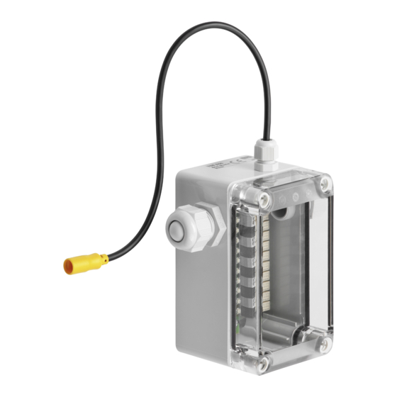
- Page 1 BMS module binary Instructions for Use For flushing stations with Viega Hygiene+ function Model Year built: 2241.68 from 11/2017 en_INT...
- Page 2 BMS module binary 2 from 12...
-
Page 3: Table Of Contents
Table of contents Table of contents About these instructions for use Target groups Labelling of notes About this translated version Product information Intended use 2.1.1 Areas of use of the BMS module Product description 2.2.1 Overview 2.2.2 Technical data Handling Assembly information 3.1.1 Required material and tools... -
Page 4: About These Instructions For Use
This restriction does not extend to possible operating instructions. The installation of Viega products must take place in accordance with the general rules of engineering and the Viega instructions for use. -
Page 5: About This Translated Version
About these instructions for use About this translated version This instruction for use contains important information about the choice of product or system, assembly and commissioning as well as intended use and, if required, maintenance measures. The information about the products, their properties and application technology are based on the current standards in Europe (e. -
Page 6: Product Information
Intended use 2.1.1 Areas of use of the BMS module The BMS module 2241.68 is suitable exclusively for flushing stations with Viega+ Hygiene function, models 2241.10 and 2241.20. For detailed installation instructions, refer to the instructions for use for the flushing station. -
Page 7: Technical Data
Art. no. Product description 2241.68 739 200 BMS module binary For binary communication/connection of flushing station with Viega Hygiene+ tech‐ nology Activation of potential-free working binary inputs and binary outputs of building auto‐ mation connection adapter Splash water protected, IP54... -
Page 8: Handling
Handling 3 Handling Assembly information 3.1.1 Required material and tools Required tools for mounting with self-tapping screws: Drill (diameter 3 mm) Assembly 3.2.1 Mounting the BMS module on the basic holder system The eight binary inputs of the BMS module are marked I1 to I8. Addi‐ tionally, the clamp-type terminals are colour-coded alternately. - Page 9 Handling Mounting with self-tapping screws Mark the positions of the mounting holes. Drill the mounting holes (bore diameter: 3 mm). Use the self-tapping screws to fasten the BMS module on the basic holder system. BMS module binary 9 from 12...
-
Page 10: Mounting And Connecting The Bms Module
Handling 3.2.2 Mounting and connecting the BMS module Unscrew the cable screw connection. Remove the protective plug. Screw the connection on. Insert the connection cable max. 14 x 2 x 0.8 (single core max. 0.8 mm Ø approx. 0.5 mm Tighten the cable screw connection. -
Page 11: Switching On
Handling Strip 8 mm of the single cores. Plug the single cores in the respective slot at an angle of approx. 45°. NOTICE! Connecting the connection plug to the control too soon will damage the flushing station. At this step, do not connect the connection plug to the con‐ trol. -
Page 12: Disposal
Handling Disposal Separate the product and packaging materials (e. g. paper, metal, plastic or non-ferrous metals) and dispose of in accordance with valid national legal requirements. Electronic components and batteries must not be put in the domestic waste but must be disposed of appropriately in conformity with the WEEE guideline 2012/19/EU.
Need help?
Do you have a question about the 2241.68 and is the answer not in the manual?
Questions and answers