Table of Contents
Advertisement
Quick Links
Advertisement
Table of Contents

Subscribe to Our Youtube Channel
Related Manuals for Kontron KBox A-150-HSW


Summary of Contents for Kontron KBox A-150-HSW
- Page 1 USER GUIDE KBox A-150-HSW Doc. Rev. 1.0 Doc. ID: 1062-3587 www.kontron.com // 1...
- Page 2 KBox A-150-HSW - Rev. 1.0 This page has been intentionally left blank www.kontron.com // 2...
- Page 3 In cases of doubt, please contact Kontron. This user guide is protected by copyright. All rights are reserved by Kontron. No part of this document may be reproduced, transmitted, transcribed, stored in a retrieval system, or translated into any language or computer language, in any form or by any means (electronic, mechanical, photocopying, recording, or otherwise), without the express written permission of Kontron.
- Page 4 ENVIRONMENTAL DAMAGE (COLLECTIVELY, "HIGH RISK APPLICATIONS"). You understand and agree that your use of Kontron devices as a component in High Risk Applications is entirely at your risk. To minimize the risks associated with your products and applications, you should provide adequate design and operating safeguards.
- Page 5 If you have any difficulties using this user guide, discover an error, or just want to provide some feedback, contact Kontron support. Detail any errors you find. We will correct the errors or problems as soon as possible and post the revised user guide on our website.
-
Page 6: Symbols
KBox A-150-HSW - Rev. 1.0 Symbols The following symbols may be used in this user guide DANGER indicates a hazardous situation which, if not avoided, will result in death or serious injury. WARNING indicates a hazardous situation which, if not avoided, could result in death or serious injury. -
Page 7: For Your Safety
Therefore, in the interest of your own safety and of the correct operation of your new Kontron product, you are requested to conform with the following guidelines. -
Page 8: Lithium Battery Precautions
General Instructions on Usage In order to maintain Kontron’s product warranty, this product must not be altered or modified in any way. Changes or modifications to the product, that are not explicitly approved by Kontron and described in this user guide or received from Kontron Support as a special handling instruction, will void your warranty. -
Page 9: Table Of Contents
KBox A-150-HSW - Rev. 1.0 Table of Contents Symbols ..........................................6 For Your Safety ........................................7 High Voltage Safety Instructions .................................. 7 Special Handling and Unpacking Instruction ............................7 Lithium Battery Precautions ..................................8 General Instructions on Usage ..................................8 Quality and Environmental Management .............................. - Page 10 KBox A-150-HSW - Rev. 1.0 6.1.2. Internal mSATA SSD ..................................... 25 6.2. Expansion Cards –mPCIe ..................................25 Accessing Components ................................... 26 7.1. Accessing External Components................................. 26 7.1.1. HDD/SSD Drive Bay ....................................26 7.2. Accessing Internal Components ................................. 27 7.2.1. Opening the Chassis ..................................... 27 7.2.2.
-
Page 11: List Of Tables
KBox A-150-HSW - Rev. 1.0 12.3.13. Front Panel 1 Pin Header (FP1) ..............................47 12.3.14. Front Panel 2 Pin Header (FP2) ..............................48 12.3.15. Primary 24-bit, 2-channel LVDS Panel Connector (LVDS1) ....................48 12.3.16. mPCIe Express v 1.2 socket /mSATA (MPCIE1) ........................49 12.3.17. -
Page 12: List Of Figures
Table 22: Save and Exit Setup Menu Sub-screens and Functions ....................64 Table 23: List of Acronyms ................................... 70 List of Figures Figure 1: KBox A-150-HSW ..................................... 15 Figure 2: Type Label ......................................19 Figure 3: KBox A-150-HSW Overview................................ 20 Figure 4: Front View (External HDD/SSD drive bay variant) ...................... -
Page 13: 1/ General Safety Instructions For It Equipment
Kontron is exempt from accident liability, this also applies during the warranty period. The product has been built and tested according to the basic safety requirements for low voltage (LVD) applications and has left the manufacturer in safety-related, flawless condition. - Page 14 KBox A-150-HSW - Rev. 1.0 Additional safety instructions for DC power supply circuits To guarantee safe operation of devices with DC power supply voltages larger than 60 volts DC or a power consumption larger than 240 VA, please observe that: ...
-
Page 15: 2/ Introduction
The KBox A-150-HSW offers high processor performance at low power dissipation by an Intel® Core™ i5-4300U processor. Due to the varied amount of onboard interfaces such as GbE, USB 3.0, USB 2,0, DisplayPort, the KBox A- 150-HSW enables connectivity for nearly all applications and supports memory expandability via mSATA SSD memory expansion. -
Page 16: 3/ Standards And Approvals
KBox A-150-HSW - Rev. 1.0 3/ Standards and Approvals The KBox A-150-HSW conforms to the requirements of the following standards. If the user modifies the product, prerequisites for specific approvals such as CE conformity declaration (safety requirements) may no longer apply. -
Page 17: 4/ Shipment And Unpacking
Please keep the associated paperwork. It contains important information for handling the unit. Check the contents for visible shipping damage. If you notice any shipping damage or inconsistencies between the contents and your order, contact Kontron for help and information. -
Page 18: Accessories
0=none; 1=W7P; 2=W7U; 3=W8.1; 4=W10; 5=LIN System Table 3: Product Versions Product Part Description KBox A-150-HSW with KBox A-150-HSW/RE-Rail-PC; KEEX-5101 i5-4300U; 4 GB DDR-3- SSD drive bay SODIMM, drive bay for SSD KBox A-150-HSW KBox A-150-HSW/RE-Rail-PC; KEEX-5101 i5-4300U; 4 GB DDR-3- (standard) SODIMM 4.4.1. -
Page 19: Type Label And Product Identification
KBox A-150-HSW - Rev. 1.0 4.7. Type Label and Product Identification The type label is position on the side of the chassis. Figure 2: Type Label Product name (KBox A-150-HSW) Model number with barcode Serial Number (S/N) with barcode For internal product use... -
Page 20: 5/ Product Overview
KBox A-150-HSW - Rev. 1.0 5/ Product Overview The KBox A-150-HSW is based on the industrial grade box PC with Intel® ULT i5-4300U (option: w/ i7-4650) processor. The series is a fanless device with passive cooling. Operating systems are Windows 7, Windows 10 or Linux. -
Page 21: Front View
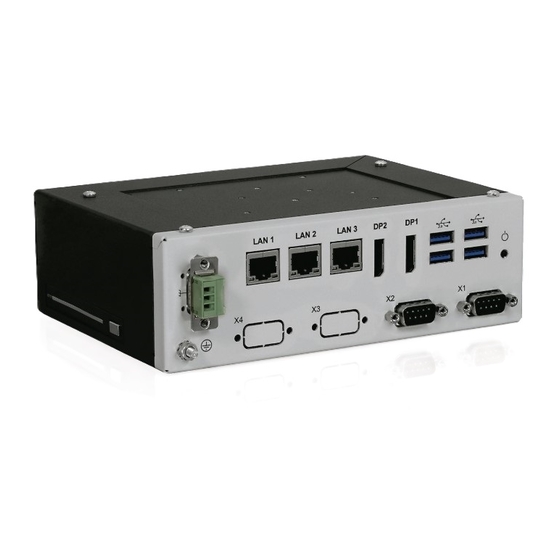
KBox A-150-HSW - Rev. 1.0 5.1. Front View Figure 4: Front View (External HDD/SSD drive bay variant) Power Connector Protective Earth stud bolt 3x GbE 2x COM 2x DisplayPort 4x USB 3.0 Power Button www.kontron.com // 21... -
Page 22: Power Connector (Pwr)
There is a Protective Earth stud bolt on the front panel connected to the chassis GND inside the system. The position of the ground pin varies depending on whether the KBox A-150-HSW is delivered with a HDD/SSD drive bay see Figure 4: Front View (External HDD/SSD drive bay variant)(pos. -
Page 23: Power Button
KBox A-150-HSW - Rev. 1.0 5.1.6. Power Button A power button is available on the front panel, see Figure 4 (pos.5). The power button performs an orderly system shut down with no loss of data and then reapplies power to resume operation. -
Page 24: Side Views
KBox A-150-HSW - Rev. 1.0 5.2.2. Side views 5.2.2.1. Side Views with HDD Figure 8: Left and Right View 5.2.2.2. Side Views without HDD Figure 9: Left and Right View 5.3. Bottom View Figure 10: Bottom View Front panel fastening screw www.kontron.com... -
Page 25: 6/ System Extension
6.1.2. Internal mSATA SSD To expand storage memory an Internal mSATA SSD of up to 512 GB can be installed. Kontron recommends the use of Kontron reference SSDs from 32 GB to 512 GB. For more information, refer to Table 2: Product Variants Before installing or removing an existing internal SSD, refer to Chapter 7.2.2: Installing and Removing Internal mSATA... -
Page 26: 7/ Accessing Components
7.1.1. HDD/SSD Drive Bay The KBox A-150-HSW variant including an external HDD/SSD drive bay supports the use of 9.5 mm high SSD drives and 7 mm SSD drives in the HDD/SSD drive bay. To insure that 7 mm high SSDs are correctly connected and to avoid damage to the internal SATA connectors an adapter/spacer must be attached to 7 mm SSD drives to enables the 7mm SSD drives to mount correctly in the drive bay’s connection points. -
Page 27: Accessing Internal Components
To access the internal components open the KBox A-150-BT chassis by following the step below: The KBox A-150-HSW is factory configured to meet customer requirements. Kontron does not recommend opening the system as this may cause damage to internal components. -
Page 28: Installing And Removing Internal Msata Ssd
Press the mSATA SSD card down (on the side with the fixing holes) until the mSATA SSD card snaps in the fixing clips. In order to close the KBox A-150-HSW, proceed in reverse order (step 6 )of Chapter 7.2.1. To remove an mSATA SSD proceed according to the steps described: Close all applications;... - Page 29 Slide the fixing clips outwards in order to release the mini PCIe card. The mini PCIe card springs up at an angle of approx. 45° on the fixing clips side. Gently pull the mini PCIe card out of the socket. In order to close the KBox A-150-HSW, proceed in reverse order (step 6) of Chapter7.2.1Opening the Chassis. www.kontron.com // 29...
-
Page 30: 8/ Thermal Considerations
An optional turnable heatsink with cooling fins is available for installation on the heatsink plate. The heatsink cooling fins are tunable by 90° and can be fitted on the KBox A-150-HSW to suit each possible installation position by remain in the vertical position to support the direction of the air flow within the DIN rail enclosure or housing. The heatsink support the use of the DIN rail. -
Page 31: 9/ Installation Instructions
9/ Installation Instructions 9.1. DIN Rail Mounting The KBox A-150-HSW is a rail mount PC box designed for use in a DIN rail enclosure or housing by attaching a DIN rail mounting clamp. The DIN rail mounting clamp can be attached on: ... -
Page 32: Power Connector
9.2. Power Connector The KBox A-150-HSW is connected by the Input power connector on the front panel to a DC power source via a DC power supply wiring consisiting of the Phoenix power mating connector (3 pin Phoenix PSC 1,5/ 3-F ) delivered with the KBox A-150-HSW and the assembled wires. - Page 33 KBox A-150-HSW - Rev. 1.0 Loosen the slotted pan head screws of the Phoenix power mating connector far enough so that you can insert the end of the prepared wires. Insert the wires into the corresponding clamp of the Phoenix power mating connector. Make sure that you have the right polarity of the connection.
-
Page 34: 10/ Starting Up
Before using your system, become familiar with the system components and follow the startup instructions below. 10.1. Connecting to Power Supply The KBox A-150-HSW connects to a DC main power supply via a Phoenix power connector on the KBox A-150 HSW’s front panel and corresponding power cable. -
Page 35: 11/ Technical Data
KBox A-150-HSW - Rev. 1.0 11/ Technical Data 11.1. Block Diagram Figure 18: Block Diagram www.kontron.com // 35... -
Page 36: Technical Specification
KBox A-150-HSW - Rev. 1.0 11.2. Technical Specification Table 5: Technical Data Designation KBox A-150 HSW Processor Intel® Core™ i5-4300U Speed 1.9/2.9 GHz (Burst) BIOS AMI® Aptio V5 Memory Technology DDR3L Max. Capacity 8 GB Interfaces Graphics Ports 2x Display Port 4x USB 3.0... -
Page 37: Figure 19: Dimensions Top Side
KBox A-150-HSW - Rev. 1.0 For more detailed mechanical information, refer to the outline dimensions drawings within this chapter. Each dimension drawing shows the main external mechanical features such as the position and size of mounting holes for the DIN rail retaining clamp. -
Page 38: Figure 21: Dimensions Front Side (50.00 Mm Without Hdd, With Hdd Height Is 58.00 Mm)
KBox A-150-HSW - Rev. 1.0 Figure 21: Dimensions Front Side (50.00 mm without HDD, with HDD height is 58.00 mm) Figure 22: Dimensions Rear Side (50.00 mm without HDD, with HDD height is 58.00 mm) Figure 23: Dimensions Left and Right Sides (50.00 mm without HDD, with HDD height is 58.00 mm) www.kontron.com... -
Page 39: Power Specification
11.4. Power Specification The KBox A-150-HSW has no internal power supply and is powered by a 3-pin DC connector on the front panel. The standard PSU voltage is 24 V DC which is converted using an internal 24 VDC to 12 VDC converter to supply the mainboard with +12 V DC. -
Page 40: 12/ Interface Pin Assignments
KBox A-150-HSW - Rev. 1.0 Interface Pin Assignments 12.1. External Connector Pin Assignment 12.1.1. GBE LAN RJ45 Connector (CN11, CN12, CN13) Table 10: GBE LAN Connector RJ45 (female) Signal Name Signal Name TX1+ TX3- TX1- TX2- TX2+ TX4+ TX3+ TX4+... -
Page 41: Input Power Connector (Pwr)
KBox A-150-HSW - Rev. 1.0 12.1.4. Input Power Connector (PWR) Figure 24: Input Power Functional Earth Figure 25: Mating Connector Manufacturer: Phoenix Contact Product: PSC 1,5/ 3-F Order#: 1841909 12.1.5. DisplayPort Port-1 Connector and Dual Mode Port-2 Connector Table 14: DisplayPort... -
Page 42: Internal Connectors Overview
KBox A-150-HSW - Rev. 1.0 12.2. Internal Connectors Overview Figure 26: Mainboard Top View Table 15: Mainboard Internal Connectors Number Label Description Front Panel 2 Pin Header Front Panel 1 Pin Header SATA1/SATA2 2x SATA SATA HDD Power CN15 RS-232/422/485 Port 1 Wafer... -
Page 43: Internal Connector Pin Assignment
KBox A-150-HSW - Rev. 1.0 MPCIE2 Mini-PCIE Express v1.2 Socket (Half Size) CN18 Backlight Power Output Wafer for LVDS1 DIMM1 DDR3 Memory SO-DIMM Socket Front Panel 1 Pin Header USB2.0 Port 4, 5 Pin Header CR2032 Battery FAN1 CPU Fan Wafer... - Page 44 KBox A-150-HSW - Rev. 1.0 USB_A+ USB_B+ www.kontron.com // 44...
-
Page 45: Right Channel 2W Audio Amp Output Wafer (Cn7)
KBox A-150-HSW - Rev. 1.0 12.3.4. Right Channel 2W Audio AMP Output Wafer (CN7) Signal Name Speaker+ Speaker- Pitch: 2.0 mm 12.3.5. Left Channel 2W Audio AMP Output Wafer (CN8) Signal Name Speaker+ Speaker- Pitch: 2.0 mm 12.3.6. Audio Pin Header (CN9) -
Page 46: Rs-232/422/485 Port 1 Wafer (Cn15)
KBox A-150-HSW - Rev. 1.0 12.3.8. RS-232/422/485 Port 1 Wafer (CN15) RS-232 RS-422 Half Duplex Full Duplex RS-485 RS-485 DATA- DATA+ Pitch :1.25mm 12.3.9. RS-232/422/485 Port 2 Wafer (CN16) RS-232 RS-422 Half Duplex Full Duplex RS-485 RS-485 DATA- DATA+ Pitch :1.25mm 12.3.10. -
Page 47: Backlight Power Output Wafer For Lvds1 (Cn18)
KBox A-150-HSW - Rev. 1.0 12.3.11. Backlight Power Output Wafer for LVDS1 (CN18) Signal Name BL_ADJ_PWM * BL_ADJ_VOL * +5V / +12V ** +5V / +12V ** BL_EN*** Pitch :1.25mm, *:BL_ADJ can be set in BIOS setup. **:Backlight Power can be selected by JP1. -
Page 48: Front Panel 2 Pin Header (Fp2)
KBox A-150-HSW - Rev. 1.0 12.3.14. Front Panel 2 Pin Header (FP2) Signal Name Signal Name Power LED + Power Button + Power Button - Power LED - SMBALERT# BatLow# SMBus DATA SMBus Clock Pitch : 2.54 mm 12.3.15. Primary 24-bit, 2-channel LVDS Panel Connector (LVDS1) -
Page 49: Mpcie Express V 1.2 Socket /Msata (Mpcie1)
KBox A-150-HSW - Rev. 1.0 12.3.16. mPCIe Express v 1.2 socket /mSATA (MPCIE1) Signal Name Signal Name WAKE# +3.3VSB Reserved Ground Reserved +1.5V CLKREQ# Ground REFCLK- REFCLK+ Ground Reserved Ground Reserved W_Disable# Ground PERST# PERn0 +3.3VSB PERp0 Ground Ground +1.5V... -
Page 50: Mpcie Express V1.2 Socket (Mpcie2)
KBox A-150-HSW - Rev. 1.0 12.3.17. mPCIE Express V1.2 Socket (mPCIE2) Signal Name Signal Name WAKE# +3.3VSB Reserved Ground Reserved +1.5V CLKREQ# UIM_PWR Ground UIM_DATA REFCLK- UIM_CLK REFCLK+ UIM_RESET Ground UIM_VPP Reserved Ground Reserved W_Disable# Ground PERST# PERn0 +3.3VSB PERp0... -
Page 51: Dc To 12V Dc Converter
KBox A-150-HSW - Rev. 1.0 12.3.19. 24V DC to 12V DC Converter 3-pin Power (external) Signal Name Functional Earth 4-pin Power (internal) Signal Name +12 V +12V www.kontron.com // 51... -
Page 52: Jumpers
KBox A-150-HSW - Rev. 1.0 12.4. Jumpers 12.4.1. Jumpers Overview Figure 27: Mainboard Top View Table 16: Mainboard Jumpers Number Label Function Panel & Backlight Power Selection for LVDS1 AT_ATX Mode / MPCIE1 mSATA / mPCIE Selection Backlight Power Enable Selection for LVDS1... -
Page 53: Panel & Backlight Power Selection For Lvds1 (Jp1)
KBox A-150-HSW - Rev. 1.0 12.4.2. Panel & Backlight Power Selection for LVDS1 (JP1) Setting Jumper Status Backlight Power = +12 V Backlight Power = +5 V Panel Power = +3.3 V Panel Power = +5 V Pitch:2.54mm 12.4.3. AT_ATX Mode/MPCIE1 mSATA/mPCIE Selection (JP2) -
Page 54: Usb Power Selection (Jp5)
KBox A-150-HSW - Rev. 1.0 12.4.6. USB Power Selection (JP5) Jumper Status USB power will be cut off in S4 & S5 state. USB power will be cut off in deep S5 state. Pitch 2.00 mm 12.4.7. Flash Description Security Override (JP6) -
Page 55: 13/ Bios
BIOS The AMI uEFI BIOS preferences are preset and do not require further adjustment for operation. The AMI BIOS setup menus and available selection may vary. For specific Information on the BIOS for your product, contact Kontron Support. The BIOS version covered in this document might not be the latest version. The latest version might have certain differences to the BIOS options and features described in this chapter. -
Page 56: Setup Menus
KBox A-150-HSW - Rev. 1.0 13.1. Setup Menus The Setup utility features menus listed in the selection bar at the top of the screen are: Main Advanced Power Boot Security Save & Exit The currently active menu and the currently active BIOS Setup item are highlighted in white. Use the left and right arrow keys to select the Setup menus. -
Page 57: Advanced Menu
KBox A-150-HSW - Rev. 1.0 13.3. Advanced Menu The Advanced Setup menu displays sub-screens and second level sub-screens with functions, for advanced configurations. Figure 29: Advanced Menu The following table gives more information for important setup options within the Advanced Menu. Default setting are displayed in bold. - Page 58 KBox A-150-HSW - Rev. 1.0 Sub-screen Additional Sub-screens with Description DVMT Pre-Allocated> [64M, 96M, 128M, 160M, 192M, 224M, 256M, 288M, 320M, 352M, 384M, 416M, 448M, 480M, 512M] DVMT Total Gfx Mem> [128M, 256M, MAX] Primary IGFX Boot Display> [VBIOS Default, CRT, HDMI, LVDS] Active LVDS>...
- Page 59 KBox A-150-HSW - Rev. 1.0 Sub-screen Additional Sub-screens with Description Configuration> XHCI Legacy Support> [Enabled, Disabled] XHCI hand-off> [Enabled, Disabled] EHCI hand-off> [Enabled, Disabled] USB Mass Storage Driver [Enabled, Disabled] Support> Intel Rapid Start [Enabled, Disabled] Security Device Support [Enabled, Disabled]...
-
Page 60: Power Menu
KBox A-150-HSW - Rev. 1.0 13.4. Power Menu Figure 30: Power Menu Table 19: Power Menu Sub-screen Additional Sub-screens with Description ACPI Sleep State [S3 only, Suspend disabled] Restore AC Power [Power off, Power on, Last state] Loss Power Saving... -
Page 61: Boot Menu
KBox A-150-HSW - Rev. 1.0 13.5. Boot Menu The Boot Setup menu lists the dynamically generated boot-device priority order Figure 31: Boot Menu The following table gives more information for important setup options within the Boot Menu. Default setting are displayed in bold. -
Page 62: Security Menu
KBox A-150-HSW - Rev. 1.0 13.6. Security Menu The Security Setup menu provides information about the passwords and functions for specifying the security settings such as Hard Disk, user and master passwords. Figure 32: Security Menu The following table gives more information for important setup options within the Security Menu. Default setting are displayed in bold. -
Page 63: Table 21: Security Setup Menu Sub-Screens And Functions
KBox A-150-HSW - Rev. 1.0 Table 21: Security Setup Menu Sub-screens and Functions Function Description Administrator Sets administrator password Password> User Password> Sets user password HDD Security Read Only Information Configuration> Allows access to set, modify and clear Hard Disk user and master passwords. -
Page 64: Save And Exit
KBox A-150-HSW - Rev. 1.0 13.7. Save and Exit Figure 33: Save and Exit Menu Table 22: Save and Exit Setup Menu Sub-screens and Functions Function Description Save Changes and Exits system after saving changes Reset> Once you are finished making your selections, choose this option from the Exit menu to ensure the values you selected are saved to the CMOS RAM. - Page 65 KBox A-150-HSW - Rev. 1.0 Function Description Load Failsafe Default values for all the setup values This option allows you to load failsafe default values for each of the parameters on the Setup menus, that provides the most stable performance settings. The F8 key can be used for this operation.
-
Page 66: 14/ Technical Support
RMA number. The buyer accepts responsibility for all freight charges for the return of goods to Kontron's designated facility. Kontron will pay the return freight charges back to the buyer's location in the event that the equipment is repaired or replaced within the stipulated warranty period. Visit the RMA Information website before returning any product to Kontron. -
Page 67: 15/ Storage, Transportation And Maintenance
When packing or unpacking products always take shock and ESD protection into consideration and use an EOS/ESD safe working area. 15.3. Maintenance Maintenance or repair on the open product may only be carried out by qualified personnel authorized by Kontron. Equipment from Kontron Europe requires only minimum servicing and maintenance for problem-free operation. Cleaning ... -
Page 68: 16/ Warranty
Limitation/Exemption from Warranty Obligation In general, Kontron shall not be required to honor the warranty, even during the warranty period, and shall be exempted from the statutory accident liability obligations in the event of damage caused to the product due to failure to observe the following: ... -
Page 69: 17/ Disposal
Many of the components used are capable of being recycled. Kontron follows the Waste Electrical and Electronic Equipment (WEEE) Directive that aims to reduce waste arising from Electrical and Electronic waste and therefore encourages customers to return Kontron products for proper disposal. -
Page 70: Appendix A: List Of Acronyms
KBox A-150-HSW - Rev. 1.0 Appendix A: List of Acronyms Table 23: List of Acronyms Application Programming Interface PCIe PCI-Express PECI Base Management Controller Platform Environment Control Interface Command-Line Interface PICMG® PCI Industrial Computer Manufacturers Group Computer-on-Module Real Time Clock... -
Page 71: About Kontron
About Kontron Kontron is a global leader in embedded computing technology (ECT). As a part of technology group S&T, Kontron offers a combined portfolio of secure hardware, middleware and services for Internet of Things (IoT) and Industry 4.0 applications. With its standard products and tailor-made solutions based on highly reliable state-of-the-art embedded technologies, Kontron provides secure and innovative applications for a variety of industries.
Need help?
Do you have a question about the KBox A-150-HSW and is the answer not in the manual?
Questions and answers