Advertisement
Quick Links
IMPORTANT SAFEGUARDS
When using electrical equipment, basic safety precautions should always be
followed including the following:
READ AND FOLLOW ALL SAFETY
INSTRUCTIONS
1.
DANGER- Risk of shock- Disconnect power before installation.
Danger – Risque de choc – Couper l'alimentation avant l'installation.
2.
This luminaire must be installed in accordance with the NEC or your local
electrical code. If you are not familiar with these codes and requirements,
consult a qualified electrician.
Ce produit doit être installé conformément à NEC ou votre code électrique
local. Si vous n'êtes pas familier avec ces codes et ces exigences, veuillez
contacter un électricien qualifié.
3.
Check to make sure that all the fixture connections have been properly made
and the fixture is grounded to avoid potential electrical shocks.
4.
Do not handle energized module with wet hands or when standing on wet or
damp surfaces, or in water.
5.
Suitable for damp locations.
Convient aux emplacements humides.
SAVE THESE INSTRUCTIONS FOR
FUTURE REFERENCE
WARNING - Maximum connected load with a single power supply shall not exceed
maximum ampacity rating of #12 AWG THHN through-wire conductors. Use only
lighting controls with relay or FET-based outputs, or lighting controls with neutral
connection. Reference www.cree.com/lighting for recommended dimming control
options. Avoid handling LEDs directly. Not intended for use in environments
containing airborne corrosive agents such as chemical solvents, cleaners, or
cutting fluids
To InsTall:
1
Cross Brace
2
Cross Brace
1 of 4
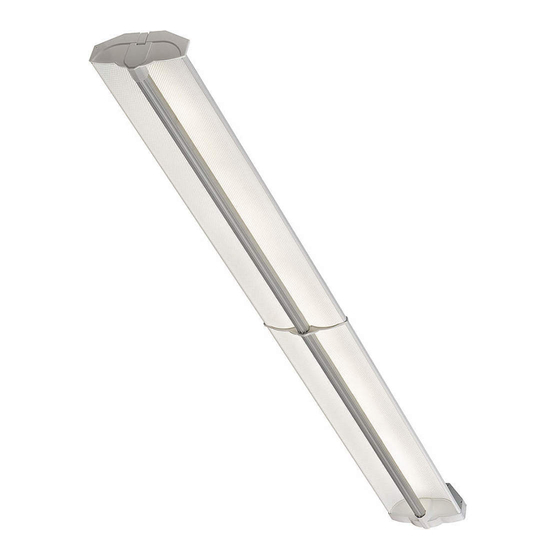
CS Series With Cree SmartCast
CS14™, CS18™ LED Linear Luminaire
InStruCtIonS D'InStaLLatIon
• The CS Series LED linear luminaire is for
suspended, with cable or threaded rod, or
surface mount applications using appropriate
tong hangers. Reference individual mounting
accessory installation instructions for specific
mounting types.
• Designed for use in 120–277V, 50-60 Hertz
protected circuit (fuse box, circuit breaker) and
supply wire shall be rated minimum 12AWG,
600V, 90 C rated).
noTE: When removing luminaire from packaging, keeping
protective plastic wrap on fixture during installation and
construction.
For PlasTIc Tong HangErs (TM):
noTE: center hole can accommodate 1/2" diameter rod
maximum.
sTEP 1:
Remove cross brace and securely insert it into the "+" shaped
openings in the plastic tong hanger. See Figures 1 & 2. For
single units or end row fixtures, place the plastic tong hanger
assembly into center spine no more than 18" from each end
of fixture and twist approximately 45 degrees until the plastic
tong hanger assembly is securely in place and approximately 90
degrees to the length of fixture. See Figure 3.
sTEP 2:
For continuous row installation, continue with next fixture using
a minimum of one tong hanger per unit. Each bracket should be
properly snug and be difficult to slide along the back spine.
®
Technology
8' and 4' Luminaires
InStaLLatIon InStruCtIonS
LPN00212X0003A8
Advertisement

Subscribe to Our Youtube Channel
Related Manuals for Cree CS14


Summary of Contents for Cree CS14
- Page 1 (fuse box, circuit breaker) and lighting controls with relay or FET-based outputs, or lighting controls with neutral connection. Reference www.cree.com/lighting for recommended dimming control supply wire shall be rated minimum 12AWG, options. Avoid handling LEDs directly. Not intended for use in environments 600V, 90 C rated).
- Page 2 For oPTIonal METal Tong HangErs (TMM): noTE: center hole can accommodate 3/8" diameter rod maximum. recommended for surface mount installations. sTEP 1: For single units or end row fixtures, place metal tong hanger bracket over center spine no more than 18" from each end of fixture.
- Page 3 ElEcTrIcal connEcTIons For connEcTIng MUlTIPlE lUMInaIrEs TogETHEr: sTEP 1: Attach two fixtures together with screws & nuts provided. See Figure 8. sTEP 2: Remove endcap cover of first fixture to reveal through- wiring plug. Open swing door of connecting fixture and remove knockout and extend wiring in preparation for connections.
- Page 4 Customer Service. If light is unresponsive, use Cree Configuration Tool to verify configuration. © 2016 Cree, Inc. All rights reserved. For informational purposes only. Content is subject to change. See http://lighting.cree.com/warranty for warranty and specifications. Cree and SmartCast are registered trademarks, and ®...
Need help?
Do you have a question about the CS14 and is the answer not in the manual?
Questions and answers