Advertisement
Quick Links
Document:
LPN00523X000140
INSTALLATION INSTRUCTIONS
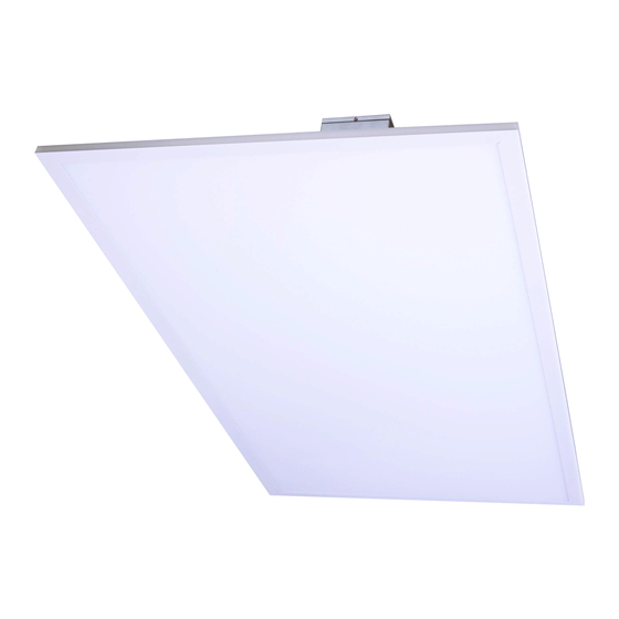
C-TR-A-FP LED Flat Panel
E.LITE
LED
LIGHTING
BY
CREE
A
"or,o*,
IMPORTANT SAFEGUARDS
When
using electrical equipment, basic safety
precautions should always
be
followed including the
following:
READ AND FOLLOW
ALL
SAFETY
INSTRUCTIONS
1.
DANGER-
Risk of
shock-
Disconnect power before
installation.
DANGER
-
Risque de choc
-
Couper
l'alimentation
avant l'installation.
2.
Caution
-
Risk
of
Fire.
Attention
-
Risque D'incendie
3.
This luminaire must be installed
in
accordance with the
nec
or
your local electrical code.
lf
you are
not
familiar
with these codes and requirements, consult
a
qualified
electrician.
Ce
produit doit
ete
instail4 conformdment
A
nec ou
votre
code 4lectrique local. Si
vous
n'€tes
pas
familier
avec
ces
codes et ces exigences, veuillez contacter
un
6lectricien
qualifi6.
4.
Suitable for damp locations.
Convient aux emplacements humides.
5.
Min
90"C
supply conductors.
Les
fils
d'alimentation 90"C min.
6.
lnherentlyprotected.
Protection inherente.
7.
Type
lC. Vapor barrier must be suitable
lor
90"C.
Type
lC.
Le
pare-vapeur
doit convenir
pour
90"C.
SAVE THESE INSTRUCTIONS
FOR
FUTURE REFERENCE
INSTALLATION
1.
Locate desired fixture location in ceiling grid.
2.
Remove existing ceiling panel at chosen location. Remove
adjacent ceiling panel to allow for wiring access from above.
3.
Place
fixture
into T-bar ceiling grid. Bend clips on top of
fixture
up
and
rotate out to engage with T-bar support grid. See
Figure
1.
Secure fixture to
grid
in compliance with state and local codes.
4,
Remove screw on driver wiring chamber
and
remove cover. Set
screw and cover aside to be reinstalled later.
5.
Remove
appropriate
1/2" knockout(s) to allow
lor
entry of supply
wiring into wiring chamber.
6.
Make wiring connections per
the Fixture
Wiring
seclion.
NOTE:
.
Terminal
blocks in driver wiring chamber will accommodate
14-20 AWG solid or stranded leads.
.
For dimming connections (if used) use
Class
1
wiring
methods only.
7.
Reattach cover of wiring chamber with screw that
was
removed
in
Step 4 above.
8.
Replace adjacent
ceiling
panel removed in Step
2.
FIXTURE WIRING
Fixture is equipped
with
universal
volt driver
12O-277V
(ie. 120V, 208V, 240V or 277Y)
PHASE
TO NEUTRAL WIRING
1201277V
1.
Connect supply ground to
fixture
ground (green) lead.
2.
Connect supply common to
fixture
neutral (white) lead.
3.
Connect
supply
Vin to
fixture
hot (black) lead.
Tuck all wires carefully into wiring chamber ensuring
that
no
wires
are
pinched.
PHASE
TO
PHASE
WIRING
2O8I24OV
'l
.
Connect supply ground to fixture ground (green)
lead.
2.
Connect
supply
L1 (Hot) to
fixture
neutral (white) lead.
3.
Connect
supply
L2 (Hot) to
fixture
hot (black) lead.
Tuck all wires carefully into wiring chamber ensuring
that
no
wires are pinched.
DIMMING
1.
Grey and
violet
leads are for
0-'l0V
dimming systems.
Cap
off
if
not used.
2x2
1x4
FIGURE
1
http://l
ig
hting.cree.com/warranty
866.924.3645
Advertisement


Need help?
Do you have a question about the C-Lite C-TR-A-FP and is the answer not in the manual?
Questions and answers