Table of Contents
Advertisement
Quick Links
WARNING: FIRE OR EXPLOSION HAZARD
Failure to follow safety warnings exactly could result in serious injury, death, or property damage.
- Do not store or use gasoline or other flammable vapors and liquids in the vicinity of this or any
other appliance.
- WHAT TO DO IF YOU SMELL GAS
• Do not try to light any appliance.
• Do not touch any electrical switch; do not use any phone in your building.
• Leave the building immediately
• Immediately call your gas supplier from a neighbor's phone. Follow the gas supplier's
instructions.
• If you cannot reach your gas supplier, call the fire department.
- Installation and service must be performed by a qualified installer, service agency or the gas supplier.
A barrier designed to reduce the risk of burns from
the hot viewing glass is provided with this appliance
and shall be installed for the protection of children
and other at-risk individuals.
This appliance may be installed in an aftermarket, permanently located, manufactured home
(USA only) or mobile home, where not prohibited by local codes.
This appliance is only for use with the type of gas indicated on the rating plate. A conversion
kit is supplied with the appliance.
INSTALLER: Leave this manual with the appliance.
CONSUMER: Retain this manual for future reference.
Travis Industries, Inc.
Copyright 2019, T.I.
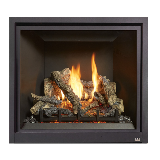
ProBuilder 36/42
CleanFace MV
Owner's Manual
HOT GLASS WILL CAUSE
BURNS
DO NOT TOUCH GLASS
UNTIL COOLED
NEVER ALLOW CHILDREN
TO TOUCH GLASS
12521 Harbour Reach Dr., Mukilteo, WA 98275
$10.00
Omni-Test Laboratories, Inc.
Operation
Maintenance
5/9/19
Tested and Listed by
Report # 0028GF115S
Portland, Oregon
ANSI Z21.88-2016
CSA 2.33-2016
CSA 2.17-2017
www.travisproducts.com
100-01490
Advertisement
Table of Contents

Related Manuals for Travis Industries Xtrordinair ProBuilder 36 CleanFace MV


Summary of Contents for Travis Industries Xtrordinair ProBuilder 36 CleanFace MV
- Page 1 This appliance is only for use with the type of gas indicated on the rating plate. A conversion kit is supplied with the appliance. INSTALLER: Leave this manual with the appliance. CONSUMER: Retain this manual for future reference. Travis Industries, Inc. 12521 Harbour Reach Dr., Mukilteo, WA 98275 www.travisproducts.com Copyright 2019, T.I.
-
Page 2: Introduction
All exhaust gases must be vented outside the structure of the living-area. Combustion air is drawn from outside the living-area structure. Notify your insurance company before hooking up this fireplace. © Travis Industries 5/9/19 - 1490 PB 36/44 CF MV Operation... -
Page 3: Table Of Contents
Approximate Heating Capacity (in square feet)* Up to 1,750 Up to 1,750 ProBuilder 42 CF Maximum BTU Input Per Hour 35,000 35,000 Heating capacity will vary with floor plan, insulation, and outside temperature. © Travis Industries 5/9/19 - 1490 PB 36/44 CF MV Operation... - Page 4 Immediately call a qualified vicinity of this heater. service technician to inspect the appliance and to replace any part of the control system and any gas control that has been under water. © Travis Industries 5/9/19 - 1490 PB 36/44 CF MV Operation...
- Page 5 If any component becomes damaged, replace with Travis Industries components. Children and adults should be Travis Industries, Inc. grants no alerted to the hazards of high warranty, implied or stated, for surface temperature and should the installation or maintenance of...
-
Page 6: Before You Begin
This dial controls the speed of the internal convection blower that pushes the heated air into the room. Optional Light Dial This dial controls the brightness of the optional accent lights (if applicable). © Travis Industries 5/9/19 - 1490 PB 36/44 CF MV Operation... -
Page 7: Starting The Pilot
“f”. Turn the gas control knob counter-clockwise to "ON". The pilot is now lit and the heater can be turned on and off. © Travis Industries 5/9/19 - 1490 PB 36/44 CF MV Operation... -
Page 8: Starting The Heater For The First Time
Your heater has an adjustable flame to tailor the look and heat output to your specific needs. It is adjusted by turning the middle dial on the gas control valve. Index Mark Flame Height Adjustment Knob Turn counter-clockwise to adjust the flame higher, clockwise to lower. © Travis Industries 9/5/19 - 1490 PB 36/44 CF MV Operation... -
Page 9: Adjusting The Blower Speed (Optional)
This is normal during start-up. You may notice the smell is more acute if the appliance was left idle for a long period. Power Outages The heater will work if household current (AC power) is disconnected. © Travis Industries 5/9/19 - 1490 PB 36/44 CF MV Operation... -
Page 10: Glass Frame Removal And Installation
Bottom Corner Top Corner Top hook engages Bottom hook this slot in bracket engages this slot in bracket Replacement Barrier Part # 36 CF ProBuilder 270-01022 42 CF ProBuilder 270-01024 © Travis Industries 5/9/19 - 1490 PB 36/44 CF MV Operation... - Page 11 NOTE: Make sure the glass frame is all the way in place - it should be parallel with the front of the fireplace when installed. Replacement Glass Frame Part # 36 CF ProBuilder 270-01009 42 CF ProBuilder 270-01025 © Travis Industries 5/9/19 - 1490 PB 36/44 CF MV Operation...
- Page 12 The latch can come loose from glass frame anchor. This occurs when it is turned 1/4 turn when it is disengaged. Follow the directions below to re-install the latch if it becomes loose. © Travis Industries 5/9/19 - 1490 PB 36/44 CF MV Operation...
-
Page 13: Probuilder 36 Log Set Installation
Rear Log Center Log Right Rear Twig 250-04842 250-04844 250-04849 Right Log 250-04846 Left Log 250-04843 Right Front Twig 250-04847 Front Left Ember Chunk Front Right Ember Chunk 250-04845 250-04848 © Travis Industries 5/9/19 - 1490 PB 36/44 CF MV Operation... - Page 14 The left log has a channel (A) on the bottom that fits over a ridge on the burner and a notch (B) that contacts the grate. Set the log in place and slide it to the rear. Front of log Bottom of log © Travis Industries 5/9/19 - 1490 PB 36/44 CF MV Operation...
- Page 15 The right front twig has a hole for a locating pin on the bottom and a notch to rest on the grate at one end. Place twig over the pin and adjust so the notch is in contact with the grate as shown below. © Travis Industries 5/9/19 - 1490...
- Page 16 The right rear twig is shown below. It has a hole for a locating pin on the bottom. When in place, the front tip just barely rests on the right log as shown below. © Travis Industries 5/9/19 - 1490...
- Page 17 Blower is a picture that shows the ember chunks side by side to aid with identification. Left Chunk Right Chunk © Travis Industries 5/9/19 - 1490 PB 36/44 CF MV Operation...
- Page 18 The right ember chunk also has a charred end. The chunk fits behind the bar, 2 from the right, of the log grate. The charred end should also be to the left as shown below. © Travis Industries 5/9/19 - 1490 PB 36/44 CF MV Operation...
-
Page 19: Probuilder 42 Log Set Installation
Number on Back of Right Rear Twig Left Twig 250-05075 Rear Log 250-05073 250-05070 Right Front Twig 250-05074 Left Log 250-05071 Right Log Left Ember Chunk Right Ember Chunk 250-05072 250-05076 250-05077 © Travis Industries 5/9/19 - 1490 PB 36/44 CF MV Operation... -
Page 20: Travis Industries
The left log has a channel (A) on the bottom that fits over a ridge on the burner and a notch (B) that contacts the grate. Set the log in place and slide it to the rear. © Travis Industries 5/9/19 - 1490... -
Page 21: Travis Industries
The right front twig has a hole for a locating pin on the bottom and a notch to rest on the grate at one end. Place twig over the pin and adjust so the notch is in contact with the grate as shown below. © Travis Industries 5/9/19 - 1490... -
Page 22: Travis Industries
The right rear twig is shown below. It has a hole for a locating pin on the bottom. When in place, the front tip just barely rests on the right log as shown below. © Travis Industries 5/9/19 - 1490... -
Page 23: Travis Industries
Maintenance Center Log The center log has a hole for a locating pin on the bottom and a notch to rest on the grate at one end. © Travis Industries 5/9/19 - 1490 PB 36/44 CF MV Operation... -
Page 24: Travis Industries
The right ember chunk also has a charred end. The chunk fits behind the bar, 2 from the right, of the log grate. The charred end should also be to the left as shown below. View from above Do not block burner holes © Travis Industries 5/9/19 - 1490 PB 36/44 CF MV Operation... -
Page 25: Ember Bed Glass And Ember Material Installation (Gsr2 Only)
NOTE: We recommend that you use a piece of paper, cardboard as a shield to mask the log grate and burner from overspray (see below). © Travis Industries 5/9/19 - 1490 PB 36/44 CF MV Operation... -
Page 26: Ember Material Installation (Gsr2 Only)
NOTE: Make sure no ember material is placed directly on the burner. HINT: Add a few randomly placed ember chunks over the ember bed glass to produce a more realistic appearance. © Travis Industries 5/9/19 - 1490 PB 36/44 CF MV Operation... -
Page 27: Ember Installation
Do not use the entire bag of rockwool. Use only a small amount and save the remainder. Over-use of rockwool will diminish the glow and may cause sooting or other adverse conditions. © Travis Industries 5/9/19 - 1490 PB 36/44 CF MV Operation... -
Page 28: Maintaining Your Heater's Appearance
Use a duster to remove dust from the visible portions of the fireplace. Contact your dealer if you wish to re-paint any surfaces. Heat-resistant stove-paint (with instructions) is available from your dealer. © Travis Industries 5/9/19 - 1490 PB 36/44 CF MV Operation... -
Page 29: Yearly Service Procedure
After 15 minutes the flames should be orange/yellow and not touch the top of the firebox. If the pilot or main burners do not burn correctly, contact your dealer for service. Monitor blower operation © Travis Industries 5/9/19 - 1490... -
Page 30: Troubleshooting Table
The logs or coals are placed incorrectly See "Log Set Installation" Thin Layer of Soot Improper air shutter adjustment Adjust Air Shutter - contact your dealer Covers the Glass © Travis Industries 5/9/19 - 1490 PB 36/44 CF MV Operation... -
Page 31: Replacement Parts List
Maintenance Replacement Parts List Caution: Use only Travis Industries replacement parts. Do not use substitute materials. Warning: Do not operate appliance with the glass front removed, cracked, or broken. Replacement of the glass should be done by a licensed or qualified service person. -
Page 32: Wiring Diagram
Thermopile Thermocouple Piezo Igniter On/Off Switch (on fireplace) Brown Copper Co-Axial Wire Orange Spark Electrode White Pilot Hood Optional Wall Switch, Thermostat, or Remote Control Optional Blower Wiring © Travis Industries 5/9/19 - 1490 PB 36/44 CF MV Operation... -
Page 33: 36 Pb Safety Label
Safety Label 36 PB Safety Label The safety (listing) label is attached to the operating tag (chained to the heater near the gas control valve). A copy is shown below © Travis Industries 5/9/19 - 1490 PB 36/44 CF MV Operation... -
Page 34: Pb Safety Label
Safety Label 42 PB Safety Label The safety (listing) label is attached to the operating tag (chained to the heater near the gas control valve). A copy is shown below © Travis Industries 5/9/19 - 1490 PB 36/44 CF MV Operation... -
Page 35: Conditions & Exclusions
2. Travis Industries has the option of either repairing or replacing the defective component. 3. If your dealer is unable to repair your appliance’s defect, he may process a warranty claim through TRAVIS INDUSTRIES, INC., including the name of the dealership where you purchased the appliance, a copy of your receipt showing the date of the appliance’s purchase, and the serial number on your appliance. -
Page 36: Index
Starting the Pilot ..........7 Installation Warnings .......... 2 Wiring Diagram ..........32 Location of Controls ........... 6 Yearly Service Procedure ........ 29 Log Set Installation ........13, 19 © Travis Industries 5/9/19 - 1490 PB 36/44 CF MV Operation...
Need help?
Do you have a question about the Xtrordinair ProBuilder 36 CleanFace MV and is the answer not in the manual?
Questions and answers