Table of Contents
Advertisement
Quick Links
Advertisement
Table of Contents

Subscribe to Our Youtube Channel
Related Manuals for Insportline Holister


Summary of Contents for Insportline Holister
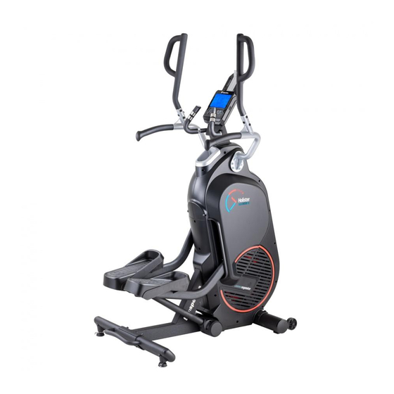
- Page 1 USER MANUAL – EN IN 20143 Stepper inSPORTline Holister...
-
Page 2: Table Of Contents
CONTENTS SAFETY PRECAUTIONS ........................3 PARTS LIST ............................4 ASSEMBLY ............................. 7 LOAD ADJUSTMENT ........................12 TRANSPORT ............................. 12 POWER CONNECTION ........................13 CONSOLE ............................. 14 BUTTON DESCRIPTION ........................14 DISPLAY ............................15 BATTERY ............................15 POWER UP............................15 PROGRAMS ............................18 QUICK START ........................... -
Page 3: Safety Precautions
SAFETY PRECAUTIONS • WARNING! This product has been designed to offer the maximum safety. Nevertheless, certain precaution should be kept while using it. Read the whole manual before first using and retain it for future reference. • It’s the owner responsibility to use it safely and properly. Instruct all other users in correct using. -
Page 4: Parts List
PARTS LIST Unpacking Place the box on the ground so that the lid can be lifted. After opening, you will see the product as shown in the image below. Remove parts such as the handlebars, pedals, rear stabilizer, console etc. Then remove the polyfoam. -
Page 7: Assembly
ASSEMBLY STEP 1 Place the cardboard on the ground and remove the top of the carton. Lift the Main Frame and remove the polystyrene. Place the Main Frame on a raised platform. WARNING: Due to the weight of the device, lift the product in at least two people. STEP 2 Unscrew the two screwed screws (Z2) from the carton (Z1). - Page 8 STEP 3 Attach Front stabilizer (B) to Main Frame (A) with screws (J2) and washer (J3). NOTE: The screws (J2) are from STEP 2 above. STEP 4 Attach Rear Stabilizer (C) to Main Frame (A) with screws (P6) and Washer (J9). You can then place the machine on the ground.
- Page 9 STEP 5 Connect the cables (D1 and A1). Slide the Bracket Holder (D) into the Main Frame (A). Tighten the screw (J1). NOTE: Make sure the wires are properly connected. Be careful not to pinch the cables. STEP 6 Remove the 4 screws (G1) from the back of the Console (G). Connect the wires (D1, G3, G4) and the heart rate measurement cable (D4) to the Console.
- Page 10 STEP 7 Attach the Handlebar Holders R (E2) to the Main Frame (A) with the screws (P1) and Spacer rings (P2). Repeat on the left. NOTE: The right and left sides are marked (R and L). STEP 8 Insert Handles P (F2) into Handlebar Holder (E2) and tighten with screws (J6) and nut (J7). Repeat on the left.
- Page 11 STEP 9 The right and left pedals cannot be interchanged. Attach the Pedal (H1) to the Pedal Holder with the bolt (J5). Repeat on the other side. The right and left cushion treads and the front and rear cannot be interchanged. Connect as shown in Pictures 1-3.
-
Page 12: Load Adjustment
LOAD ADJUSTMENT If the console is turned on, you can set the resistance of the device using the LOAD + and LOAD - buttons. Use LOAD + to increase the resistance and reduce the resistance with LOAD -. TRANSPORT If you need to move the machine to another location, lift the rear stabilizer and place the machine on the front transport wheels. -
Page 13: Power Connection
POWER CONNECTION First, plug the power cord into the machine and then into the power outlet. OTHER FUNCTIONS It is recommended to step backwards. Adjustable stand for holding tablet or mobile. USB port for charging mobile phone, tablet. Water bottle holder. -
Page 14: Console
CONSOLE Pokud uživatel přestane šlapat po dobu 4 min, konzole vstoupí do úsporného režimu a všechna data se uloží do dalšího zapnutí. BUTTON DESCRIPTION Move up or increase resistance. DOWN Move down or reduce resistance. ENTER Confirm selection START / STOP Turn on/off program In standby mode, you can quickly turn on the Manual program. -
Page 15: Display
DISPLAY TIME Time is from 00:00 to 99:59 SPEED Current speed. The maximum speed is 99.9 km / h or miles / h. Displays revolutions per minute from 0-999 RPM. DISTANCE Displaying the distance from 0.0 to 999.9 km or miles. The user can set the target distance using the UP / DOWN buttons. - Page 16 To reset the calendar, you need to remove the battery and turn the console off and on.
- Page 17 Use UP and DOWN to select U1-U4. Press ENTER to confirm. Then enter your SEX, AGE, HEIGHT and WEIGHT data. (Pic. 7-10)
-
Page 18: Programs
PROGRAMS Choose program MANUAL – VALLEY – HILL VALLEY – HIGH LAND RIFT VALLEY – INTERVAL 10/20 – INTERVAL 20/10 – INTERVAL MAX – H.R.C QUICK START Press ENTER in the MANUAL program (Pic. 19). Start training with START / STOP (Pic. 20). The load level can be set during exercise. Press START / STOP to stop training. -
Page 19: Manual Program
MANUAL PROGRAM After selecting the MANUAL program, press ENTER (Pic. 19). The user can select a load from 1 to 16. Confirm with ENTER. You can set the TIME / DISTANCE / CALORIES / PULSE training target and start the program with START / STOP. -
Page 20: Valley / Hill Valley / High Land Rift Valley
VALLEY / HILL VALLEY / HIGH LAND RIFT VALLEY Running in the valley, uphill, steep hill. Use UP / DOWN to select the desired program (Pic. 21–23) and press ENTER to confirm. The user can set TIME and then use START / STOP to turn on the program. (Pic. 24) When the program is turned on, the countdown time will start, as soon as it reaches 0, the display will flash, and a sound signal will play. -
Page 21: Interval 10/20, Interval 20/10, Interval Max
INTERVAL 10/20, INTERVAL 20/10, INTERVAL MAX With UP / DOWN choose INTERVAL 10/20, INTERVAL 20/10, INTERVAL MAX (Pic. 25–27). Confirm with ENTER. INTERVAL 10/20 (10 sec exercise, 20 sec rest) 1. Press START, the program will turn on after 3 seconds. 2. -
Page 23: Heart Rate Control
HEART RATE CONTROL After entering the HRC program (Pic. 31), the display will show Heart Rate as a percentage of 55%, 75%, 90% and TARGET (Pic. 32-35). The user can select a value using the UP / DOWN buttons. The user can set TIME and then press START / STOP to turn on the program. When it is turned on, the countdown will start, when it reaches 0, the display will flash, and a sound signal will sound. -
Page 24: Recovery Program
RECOVERY PROGRAM After completing the training, grip the handles and press RECOVERY. All functions except TIME will stop and countdown starts from 00:60 to 00:00 (Pic. 37). The console will detect the pulse, the LCD will show RECOVERY SCANNING. If no pulse is detected, PULSE INPUT is displayed. After measurement, values from F1 to F6 are displayed (Pic. - Page 25 If the user wants to display the saved data, he must be in the main program selection menu and press RECORDED. Use the UP / DOWN buttons to navigate in the menu. (Pic. 49) You can delete data with SAVE / DELETE. You will be prompted to confirm with ENTER (Pic. 50). You can delete all data in the calendar or saved data by holding SAVE / DELETE for 6 seconds.
-
Page 26: Bluetooth And Usb
BLUETOOTH AND USB The Bluetooth icons (Pic. 53) or USB (Pic. 54) are displayed. MAINTENANCE • Use only a soft cloth and a mild detergent. • Do not clean the plastic parts with abrasives or solvents. • Wipe the sweat after each use. •... - Page 27 These Conditions of Warranty and Warranty Claims are an integral part of every Purchase Agreement made between the Seller and the Buyer. All Warranty Conditions are valid and binding, unless otherwise specified in the Purchase Agreement, in the Amendment to this Contract or in another written agreement.
- Page 28 26847264 VAT ID: CZ26847264 Phone: +420 556 300 970 E-mail: eshop@insportline.cz reklamace@insportline.cz servis@insportline.cz Web: www.inSPORTline.cz inSPORTline s.r.o. Headquaters, warranty & service center: Električná 6471, Trenčín 911 01, SK CRN: 36311723 VAT ID: SK2020177082 Phone: +421(0)326 526 701 E-mail: objednavky@insportline.cz reklamacie@insportline.cz servis@insportline.cz...
Need help?
Do you have a question about the Holister and is the answer not in the manual?
Questions and answers