Table of Contents
Advertisement
Quick Links
Download this manual
See also:
Startup Manual
Advertisement
Table of Contents

Related Manuals for SMC Networks FieldServer FS-EZX-MOD-BAC


Summary of Contents for SMC Networks FieldServer FS-EZX-MOD-BAC
- Page 1 FieldServer Modbus to BACnet Start-up Guide FS-EZX-MOD-BAC APPLICABILITY & EFFECTIVITY Effective for all systems manufactured after April 2015 Driver Version: 6.15 Document Revision:...
- Page 2 Modbus to BACnet Start-up Guide Contact Information: Thank you for purchasing the FieldServer. Please call us for Technical support of the FieldServer product. Contact Information: Sierra Monitor Corporation 1991 Tarob Court Milpitas, CA 95035 Contact number: +1 408 262-6611 +1 800 727-4377 Email: support@sierramonitor.com Website:...
-
Page 3: Table Of Contents
Modbus to BACnet Start-up Guide TABLE OF CONTENTS Equipment Set-up ..............................5 Certification ................................. 5 BTL Mark – BACnet Testing Laboratory ........................5 Supplied equipment ..............................5 Mounting ..................................6 Dimensions ................................... 6 Dimension Drawing FS-EZX-MOD-BAC ......................6 4.1.1 Specifications ................................7 Installing the EZ Gateway ............................ - Page 4 Modbus to BACnet Start-up Guide LIST OF FIGURES Figure 1 – EZ Gateway Dimension Drawing ........................... 6 Figure 2 – R2 Port connection ..............................8 Figure 3 – R1 Port connection ..............................8 Figure 4 – Power Connection ..............................9 Figure 5 –...
-
Page 5: Equipment Set-Up
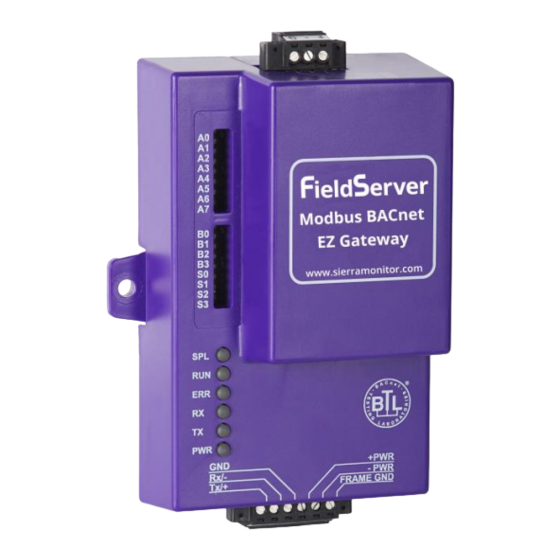
Modbus to BACnet Start-up Guide EQUIPMENT SET-UP EZ Gateway is a high performance, cost effective Building and Industrial Automation multi-protocol gateway providing protocol translation between serial and Ethernet, devices and networks. 2 CERTIFICATION BTL Mark – BACnet Testing Laboratory The BTL Mark on EZ Gateway is a symbol that indicates that a product has passed a series of rigorous tests conducted by an independent laboratory which verifies that the product correctly implements the BACnet features claimed in the listing. -
Page 6: Mounting
Modbus to BACnet Start-up Guide MOUNTING The following mounting options are available: Product comes with tabs for wall or surface mount. These can be snapped off if not required. DIN Rail Mounting Bracket - included in the Accessory Kit or ordered separately (Part # FS-8915-35- Din Rail Dimensions 4.1.1 Dimension Drawing FS-EZX-MOD-BAC... -
Page 7: Specifications
Modbus to BACnet Start-up Guide Specifications FS-EZX-MOD-BAC One 6-pin Phoenix connector with: RS-485 port (+ / - / gnd) Power port (+ / - / Frame-gnd) Available Ports One 3-pin Phoenix connector with: RS-485 port (+ / - / gnd) One Ethernet 10/100 BaseT port Input Voltage: 9-30VDC or 12-24VAC Input Power Frequency 50/60 Hz. -
Page 8: Installing The Ez Gateway
Modbus to BACnet Start-up Guide INSTALLING THE EZ GATEWAY RS-485 5.1.1 RS-485 Connection R2 port A- SG Figure 2 – R2 Port connection Connect to the 3 pins on the left-hand-side of the 6 pin connector as shown. The following Baud Rates are supported on the R2 Port: 4800, 9600, 19200, 38400, 57600, 115200 5.1.2 RS-485 Connection R1 Port Connect to the 3-pin connector as shown. -
Page 9: Operation
Modbus to BACnet Start-up Guide OPERATION Power up the device Apply power to the device. Ensure that the power supply used complies with the specifications provided in Section 4.2. Ensure that the cable is grounded using the “Frame GND” terminal. The EZ Gateway requires a power supply that provides 9-30VDC or 12-24VAC. -
Page 10: Connecting To The Ez Gateway
Modbus to BACnet Start-up Guide Connecting to the EZ Gateway 6.3.1 Using the Toolbox application to discover and connect to the EZ Gateway: Install the Toolbox application from the USB drive or get it from our website http://www.sierramonitor.com/customer-care/resource-center?filters=software-downloads Use the Toolbox application to find the EZ Gateway, and launch the Web GUI ... -
Page 11: Using A Web Browser Directly
Modbus to BACnet Start-up Guide 6.3.2 Using a Web Browser directly Open a Web Browser and connect to the EZ Gateway’s Default IP address. The Default IP Address of the BACnet Router is 192.168.2.101, Subnet Mask is 255.255.255.0 If the PC and the EZ Gateway are on different IP Networks, assign a Static IP Address to the PC on the 192.168.2.X network. - Page 12 Modbus to BACnet Start-up Guide Select Network Settings. Modify the IP address (N1 IP address field) of the EZ Gateway Ethernet port. If necessary, change the Netmask (N1 Netmask field). Type in a new Subnet Mask ...
- Page 13 Modbus to BACnet Start-up Guide Page 13 of 25...
-
Page 14: Configuring The Ez Gateway
Modbus to BACnet Start-up Guide CONFIGURING THE EZ GATEWAY Setting up the Connections The Connections page is used to setup the connection Ports & Parameters. Figure 7 – The Connections page Click the Save button in the Controls Section once completed. Page 14 of 25... -
Page 15: Creating Device Profiles
Modbus to BACnet Start-up Guide Creating Device Profiles Click on the Device Profiles and enter the name of the profile. Figure 8 – Creating Device Profiles Click on the Edit button next to the name Choose the Modbus addressing parameters ... -
Page 16: Figure 10 - Mapping Bacnet Addresses To The Modbus Registers
Modbus to BACnet Start-up Guide Figure 10 – Mapping BACnet addresses to the Modbus Registers Click on the Blue Plus next to the Address to map the BACnet Addresses to the Modbus Registers. Figure 11 – Mapping BACnet addresses to the Modbus Registers ... -
Page 17: Figure 12 - Define The State Table & Variables
Modbus to BACnet Start-up Guide Figure 12 – Define the State Table & variables If you need to define a Notification Class, click the “Notification Class” tab and define the parameters of your class. Figure 13 – Defining Parameters of Notification Class Page 17 of 25... -
Page 18: Figure 14 - Define Profiles
Modbus to BACnet Start-up Guide Once you define all of your mappings and settings, click the “Save” button to define the Profile Figure 14 – Define Profiles Once you have defined your profile, you can then export it for backup or future use by hitting the Export Profile button. -
Page 19: Importing A Device Profile
Modbus to BACnet Start-up Guide Importing a Device Profile If you have an existing exported profile you can import it to the EZ Gateway by going to the Device Profiles section, and hitting the arrow to the right of the Add button Figure 16 –... -
Page 20: Adding Device Profiles
Modbus to BACnet Start-up Guide Adding Device Profiles Click on the Profile Loader button Choose the Profile to load from the drop down. Figure 17 – Choose Profile to Load Choose the appropriate Connection and Node ID for both the incoming Modbus device and the mapped BACnet output. -
Page 21: Test And Commission The Ez Gateway
Modbus to BACnet Start-up Guide Test and Commission the EZ Gateway Connect the EZ Gateway to the third party device(s), and test the application. Click on the Diagnostic tab to view to get to Diagnostic screen. From the main menu of FS-GUI click on View, Connections to see the number of messages on each protocol. -
Page 22: Appendix A Troubleshooting Tips
Modbus to BACnet Start-up Guide Appendix A Troubleshooting Tips Appendix A.1. Communicating with the EZ Gateway over the Network Confirm that the network cabling is correct. Confirm that the computer network card is operational and correctly configured. Confirm that there is an Ethernet adapter installed in the PC’s Device Manager List, and that it is configured to run the TCP/IP protocol. -
Page 23: Appendix B Reference
Modbus to BACnet Start-up Guide Appendix B Reference Appendix B.1. LED Functions Figure 20 – LED allocation Light Description SPL LED will be on when a configured node in the EZ Gateway is detected as being offline. See Node overview screen of the FS-GUI for further details. RUN LED will flash 20 seconds after power up, signifying normal operation. -
Page 24: Appendix B.2. Compliance With Ul Regulations
Modbus to BACnet Start-up Guide Appendix B.2. Compliance with UL Regulations For UL compliance, the following instructions must be met when operating the EZ Gateway. The units shall be powered by listed LPS or Class 2 power supply suited to the expected operating temperature range. -
Page 25: Appendix C Limited 2 Year Warranty
Modbus to BACnet Start-up Guide Appendix C Limited 2 year Warranty Sierra Monitor Corporation warrants its products to be free from defects in workmanship or material under normal use and service for two years after date of shipment. Sierra Monitor Corporation will repair or replace any equipment found to be defective during the warranty period.
Need help?
Do you have a question about the FieldServer FS-EZX-MOD-BAC and is the answer not in the manual?
Questions and answers