
Related Manuals for SMC Networks Sierra Monitor ProtoNode FPC N54 Series


Summary of Contents for SMC Networks Sierra Monitor ProtoNode FPC N54 Series
- Page 1 Building Management System Gateway Kit Installation and Quick Start Guide 238-53951-00A 5/20...
-
Page 2: Table Of Contents
Table of Contents Hardware ProtoNode Installation Guide ..................3 UCG / 120T ........................3 DIN Rail Installation ........................3 ProtoNode Installation on DIN Rail ..................6 60T / 100T ........................8 DIN Rail Installation ........................8 ProtoNode Installation on DIN Rail ..................10 ProtoNode Power and Communication .............. -
Page 3: Protonode Installation Guide
UCG/ 120T Installation Only DIN Rail Installation 1) Disconnect (unplug) the water heater from 120 volt power source. 2) Latches secure the black surround hood to the appliance body with swell-actuation type fasteners. When secured, the latches are in the horizontal position. To remove the surround, all latches must be in the vertical position (120T shown, Figure 1). - Page 4 UCG/ 120T Installation Only Figure 3 d. Ensure that the mounting template is correctly lined up with the jacket head prior to drilling mounting locations (see Figure 3). e. Place the DIN rail over new or existing mounting locations. Figure 4 f.
- Page 5 UCG/ 120T Installation Only g. Drive down supplied screws to complete the DIN rail mounting (see Figure 5). Figure 5 DIN rail mounted with screws...
-
Page 6: Protonode Installation On Din Rail
UCG/ 120T Installation Only Protonode Installation 4) Install the ProtoNode on the DIN rail. a. Install the ProtoNode with the movable rail latch (circled, Figure 6) towards the back side of the water heater. Figure 6 Front of Water Heater b. - Page 7 UCG/ 120T Installation Only d. The ProtoNode should now be correctly fastened to the DIN rail. The power connection (circled in white, Figure 9) should be facing towards the front of the water heater. Figure 9...
-
Page 8: 60T / 100T
60T / 100T Installation Only DIN Rail Installation 5) Disconnect (unplug) the water heater from 120 volt power source. 6) Latches secure the black lid to the appliance surround. Disconnect two latches and remove the lid. 7) DIN Rail Installation. a. - Page 9 60T / 100T Installation Only Figure 11 d. Ensure that the mounting template is correctly lined up with the control base prior to drilling mounting locations (see Figure 11). Removal of the base is not necessary to install DIN Rail. e.
-
Page 10: Protonode Installation On Din Rail
60T / 100T Installation Only Protonode Installation 8) Install the ProtoNode on the DIN rail. a. Install the ProtoNode with the movable rail latch (circled, Figure 14) towards the SOLA controller SOLA Figure 14 b. Place the movable latch under the rail first (see Figure 15). Figure 15... - Page 11 60T / 100T Installation Only c. After the rear latch is placed under the rail, bring the ProtoNode forward to latch under the front rail (see Figure 16). Figure 16 d. The ProtoNode should now be correctly fastened to the DIN rail. The power connection (circled in white, Figure 17) should be facing towards the SOLA controller.
-
Page 12: Protonode Power And Communication
ProtoNode Power and Communication 9) Install the Power Cord for ProtoNode. a. Find the connector (white circle, Figure 18) that connects the blue and yellow wires from the transformer to the SOLA control (black square, Figure 18). Figure 18 b. Unplug the connector (see Figure 19). Figure 19... - Page 13 c. Install the ProtoNode power harness, P/N: 239-53934-00, between this connector (see Figure 20). Figure 20 d. Install the ProtoNode power harness male and female connectors into yellow and blue power harness between the Transformer and SOLA control (see Figure 21). Figure 21 e.
- Page 14 f. Install the black connector to the ProtoNode (see Figure 23). Figure 23 10) Install Communication Cable, P/N: 264-53959-00, between ProtoNode R1 port and SOLA Control (J3 port). a. The black wire is attached to the TX+ port (far left). The clear wire is attached to the RX- port (middle) (see Figure 24).
- Page 15 b. Plug harness into the R1 port on the ProtoNode (see Figure 25). Figure 25 c. Unplug the green connector from J3 location on the SOLA control. The connector is circled in white (see Figure 26). Figure 26 d. Connect the other end of the communication harness to the SOLA control. The black wire connects to the MB1 A terminal (bottom).
- Page 16 e. Reconnect the green SOLA connector once the ProtoNode cable has been installed (see Figure 28). Figure 28 11) The ProtoNode should now be successfully connected. Reconnect the 120 volt power source and continue through the remainder of the start-up guide for instruction of connecting to the Building Management System.
-
Page 17: Software
Software Certification BTL Mark – BACnet®1 Testing Laboratory The BTL Mark on the ProtoNode is a symbol that indicates that a product has passed a series of rigorous tests conducted by an independent laboratory which verifies that the product correctly implements the BACnet features claimed in the listing. -
Page 18: Protonode Setup
ProtoNode Setup Record Identification Data Each ProtoNode has a unique part number located on the side or the back of the unit. This number should be recorded, as it may be required for technical support. The numbers are as follows: Table 1 Model Part Number... -
Page 19: Interfacing Protonode To Devices
Interfacing ProtoNode to Devices Device Connections to ProtoNode The ProtoNode has a 3-pin Phoenix connector for connecting RS-485 devices on the R1 port (Figure 30). NOTE: Use standard grounding principles for RS-485 GND. ProtoNode Device Pins Pin Label Assignment RS-485 + TX + RS-485 + RS-485 -... - Page 20 NOTE: See www.ni.com/support/serial/resinfo.htm for additional pictures and notes. NOTE: The R1 and R2 DIP switches R1 Bias Resistor DIP apply settings to the respective serial Switches (2 and 3) port. NOTE: If the gateway is already R2 Bias Resistor DIP powered on, DIP switch settings will Switches (2 and 3) not take effect unless the unit is power...
-
Page 21: Connect A Pc To The Protonode
Power-Up ProtoNode Check power requirements in Table 5: Table 5 Power Requirement for ProtoNode External Gateway Current Draw Type ProtoNode Family 12VDC 24VDC/AC FPC – N54 (Typical) 250mA 125mA Note: These values are ‘nominal’ and a safety margin should be added to the power supply of the host system. -
Page 22: Protonode Configuration
Changing the Subnet of the Connected PC The default IP Address for the ProtoNode is 192.168.1.24, Subnet Mask is 255.255.255.0. If the PC and ProtoNode are on different IP networks, assign a static IP Address to the PC on the 192.168.1.xxx network. - Page 23 • Enter the previously set up or default username and password. NOTE: The default username is “admin”. The default password is “admin”. Figure 38 • From the Web App landing page (Figure 39), click the Settings tab and then click Configuration. Figure 39 •...
- Page 24 Select Field Protocol and Set Configuration Parameters • On the Web Configurator page, the first configuration parameter is the Protocol Selector. Figure 41 • Select the field protocol by entering the appropriate number into the Protocol Selector Value. Click the Submit button. Click the System Restart button to save the updated configuration. NOTE: Protocol specific parameters are only visible when the associated protocol is selected.
- Page 25 Setting ProtoNode Active Profiles • In the Web Configurator, the Active Profiles are shown below the configuration parameters. The Active Profiles section lists the currently active device profiles, including previous Web Configurator additions. This list is empty for new installations, or after clearing all configurations (Figure 42).
- Page 26 • To add an active profile to support a device, click the Add button under the Active Profiles heading. This will present a profile drop-down menu underneath the Current profile column. • Once the Profile for the device has been selected from the drop-down list, enter the value of the device’s Node-ID which was assigned in Set Node-ID for any Device Attached to the ProtoNode, (pg 19).
- Page 27 Ethernet Network: Setting IP Address for the Field Network • Follow the steps outlined in Accessing the ProtoNode Web Configurator (pg 22) to access the ProtoAir Web Configurator. • To access the FS-GUI, click on the Diagnostics & Debugging button in the bottom right corner of the page (Figure 44).
- Page 28 • From the FS-GUI landing page, click on “Setup” to expand the navigation tree and then select “Network Settings” to access the IP Settings menu (Figure 45). Figure 45 • Modify the IP Address (N1 IP Address field) of the ProtoNode Ethernet port. •...
- Page 29 BACnet: Setting Node_Offset to Assign Specific Device Instances • Follow the steps outlined in Accessing the ProtoNode Web Configurator (pg 22) to access the ProtoAir Web Configurator. • Node_Offset field shows the current value (default = 50,000). o The values allowed for a BACnet Device Instance can range from 1 to 4,194,303. •...
- Page 30 Appendix A: Troubleshooting Appendix A.1 – Lost or Incorrect IP Address • Ensure that the FieldServer Toolbox is loaded onto the local PC. Otherwise, download the FieldServer-Toolbox.zip via the Sierra Monitor website’s Software Downloads. • Extract the executable file and complete the installation. Ethernet Port Figure A1 •...
-
Page 31: Appendix A.2 - Viewing Diagnostic Information
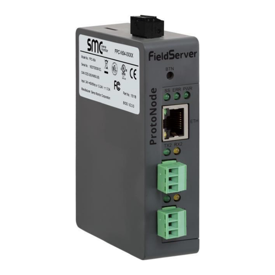
Appendix A.2 – Viewing Diagnostic Information • Type the IP address of the ProtoNode into the web browser or use the FieldServer Toolbox to connect to the ProtoNode. • Click on Diagnostics button, then click on view, and then on connections. •... - Page 32 Appendix A.4 – LED Diagnostics for Communications Between ProtoNode and Devices See Figure 51 for ProtoNode FPC-N54 LED locations. FPC-N54 Diagnostic LEDS Figure A4 Description The SS LED will flash once a second to indicate that the bridge is in operation. The SYS ERR LED will go on solid indicating there is a system error.
- Page 33 Appendix A.5 – Take a FieldServer Diagnostic Capture When there is a problem on-site that cannot easily be resolved, perform a diagnostic capture before contacting support so that support can quickly solve the problem. There are two methods for taking diagnostic captures: •...
- Page 34 • Step 1: Take a Log o Click on the diagnose icon of the desired device. Figure A6 o Ensure “Full Diagnostic” is selected (this is the default). Figure A7 NOTE: If desired, the default capture period can be changed. o Click on “Start Diagnostic”...
- Page 35 Figure A8 o Wait for Capture period to finish, then the Diagnostic Test Complete window will appear. • Step 2: Send Log Once the Diagnostic test is complete, a .zip file is saved on the PC. Figure A9 Choose “Open” to launch explorer and have it point directly at the correct folder. ...
- Page 36 Appendix A.5.2 – Using FS-GUI Completing a Diagnostic Capture through the FieldServer allows network connections (such as Ethernet and Wi-Fi) to be captured. Once the Diagnostic Capture is complete, email it to SMC Technical Support. The Diagnostic Capture will accelerate diagnosis of the problem. •...
-
Page 37: Appendix B.2 - Bacnet: Setting Network_Number For More Than One Protonode On The Subnet
Appendix B: Additional Information Appendix B.1 – Updating Firmware To load a new version of the firmware, follow these instructions: 1. Extract and save the new file onto the local PC. 2. Open a web browser and type the IP address of the FieldServer in the address bar. a. - Page 38 Appendix B.3 – Securing ProtoNode with Passwords Access to the ProtoNode can be restricted by enabling a password on the FS-GUI Passwords page – click on Setup and then Passwords in the navigation panel. There are 2 access levels defined by 2 account names: Admin and User.
- Page 39 Appendix B.4 – Factory Reset Instructions For instructions on how to reset a FieldServer back to its factory released state, see ENOTE - FieldServer Next Gen Recovery. Appendix B.5 – Internet Browsers Not Supported Internet Explorer 11 and prior versions. Appendix B.6 –...
- Page 40 Appendix B.7 – Physical Dimension Drawing Power Port R2 Serial Port R1 Serial Port Figure B5...
-
Page 41: Appendix C: Vendor Information - Bradford White
Appendix C: Vendor Information – Bradford White NOTE: All Modbus TCP/IP registers are the same as the Modbus RTU registers for the serial device. If this point list is needed, contact technical support. The Modbus TCP/IP node address of the device is also the same as the Modbus RTU node address. Appendix C.1 –... -
Page 42: Appendix D.1.1 - Compliance With Ul Regulations
Appendix D: Reference Appendix D.1 – Specifications Table 6 ProtoNode FPC-N542 One 3-pin Phoenix connector with: RS-485/RS-232 (Tx+ / Rx- / gnd) One 3-pin Phoenix connector with: RS-485 (Tx+ / Rx- / gnd) Electrical Connections One 3-pin Phoenix connector with: Power port (+ / - / Frame-gnd) One Ethernet 10/100 BaseT port Input Voltage: 9-30VDC or 24VAC Power Requirements... -
Page 45: Mounting Template For 60T / 100T Models
Notes... -
Page 46: Notes
Notes...
Need help?
Do you have a question about the Sierra Monitor ProtoNode FPC N54 Series and is the answer not in the manual?
Questions and answers