
Related Manuals for SMC Networks FieldServer FS-QS-2XX0


Summary of Contents for SMC Networks FieldServer FS-QS-2XX0
- Page 1 FieldServer QuickServer Start-up Guide FS-QS-2XX0 APPLICABILITY & EFFECTIVITY Effective for all systems manufactured after November 2019. Document Revision: 1.H T18627...
- Page 2 QuickServer Start-Up Guide Technical Support Please call us for any technical support needs related to the FieldServer product. MSA Safety 1991 Tarob Court Milpitas, CA 95035 Website: www.sierramonitor.com U.S. Support Information: +1 408 964-4443 +1 800 727-4377 Email: smc-support@msasafety.com EMEA Support Information: +31 33 808 0590 Email: smc-support.emea@msasafety.com...
-
Page 3: Table Of Contents
QuickServer Start-Up Guide TABLE OF CONTENTS QuickServer Description ........................6 Certifications ............................6 BTL Mark – BACnet Testing Laboratory..................6 Supplied Equipment ..........................6 QuickServer Setup ..........................7 Mounting ............................7 DIP Switch Settings ........................8 4.2.1 Bias Resistors.......................... 8 4.2.2 Termination Resistor ....................... - Page 4 QuickServer Start-Up Guide Appendix C Reference ..........................29 Appendix C.1. QuickServer FS-QS-2XX0-XXXX DCC ................29 Appendix C.2. QuickServer Part Numbers ....................29 Appendix C.3. Compliance with UL Regulations ..................30 Appendix C.4. Dimension Drawing FS-QS-2XX0-XXXX................. 30 Appendix C.5. Specifications ........................31 Appendix D Limited 2 Year Warranty ......................
- Page 5 QuickServer Start-Up Guide LIST OF FIGURES Figure 1: DIN Rail Bracket ..........................7 Figure 2: DIN Rail Mounted........................... 7 Figure 3: Bias Resistor DIP Switches ......................8 Figure 4: Termination Resistor DIP Switch ....................9 Figure 5: R1 & R2 Connection Ports ......................10 Figure 6: Required Current Draw for the Gateway ..................
-
Page 6: Quickserver Description
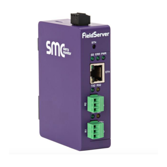
QuickServer Start-Up Guide QUICKSERVER DESCRIPTION QuickServer is a high performance, cost effective Building and Industrial Automation multi-protocol gateway providing protocol translation between serial/Ethernet devices and networks. NOTE: For troubleshooting assistance refer to Appendix B, or any of the troubleshooting appendices in the related driver supplements. Check the Sierra Monitor website technical support resources and documentation that may be of assistance. -
Page 7: Quickserver Setup
QuickServer Start-Up Guide QUICKSERVER SETUP Mounting The QuickServer can be mounted using the DIN rail mounting bracket on the back of the unit. Din Rail Bracket Figure 1: DIN Rail Bracket NOTE: For dimension details see Appendix C.4. Figure 2: DIN Rail Mounted Page 7 of 32... -
Page 8: Dip Switch Settings
QuickServer Start-Up Guide DIP Switch Settings 4.2.1 Bias Resistors R1 Bias Resistor DIP Switches (2 and 3) R2 Bias Resistor DIP Switches (2 and 3) Figure 3: Bias Resistor DIP Switches To enable Bias Resistors, move both the BIAS- and BIAS+ dip switches to the right in the Figure orientation shown in The QuickServer bias resistors are used to keep the RS-485 bus to a known state, when there is no... -
Page 9: Termination Resistor
QuickServer Start-Up Guide 4.2.2 Termination Resistor R1 Termination Resistor DIP Switch (1) R2 Termination Resistor DIP Switch (1) Figure 4: Termination Resistor DIP Switch If the QuickServer is the last device on the serial trunk, then the End-Of-Line Termination Switch needs to be enabled. -
Page 10: Connecting The R1 Port
QuickServer Start-Up Guide Connecting the R1 Port For the R1 Port only: Switch between RS-485 and RS-232 by moving the number 4 DIP Switch left for RS-485 and right for RS-232 (Figure The R2 Port is RS-485. Connect to the 3-pin connector(s) as shown below. TX+ RX- GND Figure 5: R1 &... -
Page 11: Power Up The Device
QuickServer Start-Up Guide Power Up the Device Check power requirements in the table below: Power Requirement for External Gateway Current Draw Type QuickServer Family 12VDC 24VDC/AC FS-QS-2XX0-XXXX (Typical) 250mA 125mA NOTE: These values are ‘nominal’ and a safety margin should be added to the power supply of the host system. -
Page 12: Connect The Pc To The Quickserver
QuickServer Start-Up Guide CONNECT THE PC TO THE QUICKSERVER Connecting to the Gateway via Ethernet Connect a Cat-5 Ethernet cable (straight through or cross-over) between the local PC and QuickServer. Ethernet Port Figure 8: Ethernet Port Location 5.1.1 Changing the Subnet of the Connected PC The default IP Address for the QuickServer is 192.168.2.101, Subnet Mask is 255.255.255.0. -
Page 13: Using The Fs-Gui To Set The Ip Address
QuickServer Start-Up Guide 5.1.2 Using the FS-GUI to Set the IP Address • From the FS-GUI main home page, click on setup and then Network Settings to enter the Edit IP Address Settings menu. • Modify the IP Address (N1 IP Address field) of the QuickServer Ethernet port. •... -
Page 14: Configuring The Quickserver
QuickServer Start-Up Guide CONFIGURING THE QUICKSERVER Retrieve the Sample Configuration File The configuration of the QuickServer is provided to the QuickServer’s operating system via a comma- delimited file called “CONFIG.CSV”. If a custom configuration was ordered, the QuickServer will be programmed with the relevant device registers in the Config.csv file for the initial start-up. -
Page 15: Load The Updated Configuration File
QuickServer Start-Up Guide Load the Updated Configuration File 6.3.1 Using the FS-GUI to Load a Configuration File • In the main menu of the FS-GUI screen, click “Setup”, then “File Transfer” and finally “Update”. • Browse and select the .csv file, open, then click “Submit”. Figure 11: FS-GUI Loading Files •... -
Page 16: Retrieve The Configuation File For Modification Or Backup
QuickServer Start-Up Guide 6.3.2 Retrieve the Configuation File for Modification or Backup To get a copy of the configuration file for modifying or backing up a configuration on a local computer, do the following: • In the main menu of the FS-GUI screen, click “Setup”, then “File Transfer”. Figure 12: Retrieve Configuration File •... -
Page 17: Test And Commission The Quickserver
QuickServer Start-Up Guide Test and Commission the QuickServer • Connect the QuickServer to the third party device(s), and test the application. • From the landing page of the FS-GUI click on “View” in the navigation tree, then “Connections” to see the number of messages on each protocol. Figure 13: FS-GUI Connections Page Page 17 of 32... -
Page 18: Appendix A Useful Features
QuickServer Start-Up Guide Appendix A Useful Features Appendix A.1. SSL/TLS for Secure Connection SSL/TLS (Secure Sockets Layer/Transport Layer Security) is a security technology for establishing an encrypted connection between a server and a client. This allows the secure transfer of data across untrusted networks. -
Page 19: Appendix A.1.1.2. Limiting Client Access
QuickServer Start-Up Guide Appendix A.1.1.2. Limiting Client Access In addition to TLS_Port parameter also add Validate_Client_Cert in the connections section of the configuration file and set it to “Yes”. Connections Adapter , Protocol , TLS_Port , Validate_Client_Cert , Modbus/TCP , 1502 , Yes The configuration above sets the FieldServer to request and verify a client’s certificate against its internal authority file before accepting connection. -
Page 20: Appendix A.1.1.4. Certificate Validation Options
QuickServer Start-Up Guide Appendix A.1.1.4. Certificate Validation Options If connections must be limited to only a particular domain (vendor devices), include Check_Remote_Host to specify the domain/host name. Connections Adapter , Protocol , TLS_Port , Validate_Client_Cert , Cert_Authority_File , Check_Remote_Host , Modbus/TCP , 1502 , Yes , my_authorized_clients.pem , SMC The configuration above tells the FieldServer to only accept connections that have the correct certification... -
Page 21: Appendix A.1.2. Configuring Fieldserver As Ssl/Tls Client
QuickServer Start-Up Guide Appendix A.1.2. Configuring FieldServer as SSL/TLS Client The following Node configurations set the FieldServer to open a secure Modbus/TCP connection to Server at IP Address 10.11.12.13 on port 1502. Appendix A.1.2.1. Simple Secure Client Configuration Add Remote_Node_TLS_Port parameter in the nodes section of the configuration file and set to a port number between 1 –... -
Page 22: Appendix B Troubleshooting
QuickServer Start-Up Guide Appendix B Troubleshooting Appendix B.1. Communicating with the QuickServer Over the Network • Confirm that the network cabling is correct. • Confirm that the computer network card is operational and correctly configured. • Confirm that there is an Ethernet adapter installed in the PC’s Device Manager List, and that it is configured to run the TCP/IP protocol. -
Page 23: Appendix B.2. Before Contacting Technical Support Take A Diagnostic Capture
QuickServer Start-Up Guide Appendix B.2. Before Contacting Technical Support Take a Diagnostic Capture When there is a problem on-site that cannot easily be resolved, perform a diagnostic capture before contacting support so that support can quickly solve the problem. There are two methods for taking diagnostic captures: •... - Page 24 QuickServer Start-Up Guide Step 1: Take a Log Click on the diagnose icon of the desired device Ensure “Full Diagnostic" is selected (this is the default) NOTE: If desired, the default capture period can be changed. Page 24 of 32...
- Page 25 QuickServer Start-Up Guide Click on “Start Diagnostic” When the capture period is finished, the “Diagnostic Test Complete” window will appear Step 2: Send Log Once the diagnostic test is complete, a .zip file will be saved on the PC Click “Open” to launch explorer and have it point directly at the correct folder Email the diagnostic zip file to smc-support@msasafety.com Page 25 of 32...
-
Page 26: Appendix B.2.2. Using Fs-Gui
QuickServer Start-Up Guide Appendix B.2.2. Using FS-GUI Diagnostic Capture with FS-GUI is only available on FieldServers with a bios updated/released on November 2017 or later. Completing a Diagnostic Capture through the FieldServer allows network connections (such as Ethernet and Wi-Fi) to be captured. Once the Diagnostic Capture is complete, email it to technical support. -
Page 27: Appendix B.3. Led Functions
QuickServer Start-Up Guide Appendix B.3. LED Functions FS-QS-2XX0 Diagnostic LEDs Description The SS LED will flash once a second to indicate that the bridge is in operation. The SYS ERR LED will go on solid indicating there is a system error. If this occurs, immediately report the related “system error”... -
Page 28: Appendix B.4. Securing Quickserver With Password
QuickServer Start-Up Guide Appendix B.4. Securing QuickServer with Password Access to the FieldServer can be restricted by enabling a password on the FS-GUI Passwords page – click Setup and then Passwords in the navigation panel. There are 2 access levels defined by 2 account names: Admin and User. -
Page 29: Appendix C Reference
QuickServer Start-Up Guide Appendix C Reference Appendix C.1. QuickServer FS-QS-2XX0-XXXX DCC Driver Code BACnet/IP – BACnet MS/TP 0285 JCI Metasys N2– BACnet MS/TP 0309 JCI Metasys N2– BACnet/IP 0122 Modbus RTU – BACnet MS/TP 0367 Modbus RTU – BACnet/IP 0104 Modbus RTU –... -
Page 30: Appendix C.3. Compliance With Ul Regulations
QuickServer Start-Up Guide Appendix C.3. Compliance with UL Regulations For UL compliance, the following instructions must be met when operating QuickServer. • The units shall be powered by listed LPS or Class 2 power supply suited to the expected operating temperature range. •... -
Page 31: Appendix C.5. Specifications
QuickServer Start-Up Guide Appendix C.5. Specifications FS-QS-2XX0-XXXX One 3-pin Phoenix connector with: RS-485/RS-232 (Tx+ / Rx- / gnd) One 3-pin Phoenix connector with: RS-485 (Tx+ / Rx- / gnd) Electrical Connections One 3-pin Phoenix connector with: Power port (+ / - / Frame-gnd) One Ethernet 10/100 BaseT port Input Voltage: 9-30VDC or 24VAC Current draw: 24VAC 0.125A... -
Page 32: Appendix D Limited 2 Year Warranty
QuickServer Start-Up Guide Appendix D Limited 2 Year Warranty Sierra Monitor Corporation warrants its products to be free from defects in workmanship or material under normal use and service for two years after date of shipment. Sierra Monitor Corporation will repair or replace any equipment found to be defective during the warranty period.
Need help?
Do you have a question about the FieldServer FS-QS-2XX0 and is the answer not in the manual?
Questions and answers