
Related Manuals for YOKOGAWA HANDY CAL CA51


Summary of Contents for YOKOGAWA HANDY CAL CA51
- Page 1 User’s Model CA51/71 Manual HANDY CAL Calibrators IM CA71-E IM CA71-E 1st Edition: Feb. 2002...
-
Page 2: Introduction
All other company and product names appearing in this document are trademarks or registered trademarks of their respective holders. Revision Information February 2002: First edition Disk No. CA71-E 1st Edition: Feb.2002 All Rights Reserved. Copyright © 2002, Yokogawa M&C Corporation IM CA71-E... -
Page 3: Checking Items In The Package
Checking Items in the Package After opening the package, check the product as follows before use. If the delivered product is the wrong model, any item is missing, or there are visible defects, contact the vendor from which you purchased the product. - Page 4 Checking Items in the Package Standard Accessories Make sure that the package contains all the accessories listed below and that they are all free from any damage. Carrying case Lead cables Lead cables for Fuse (93016) for source measurement (A1501EF) (98020) (RD031) Terminal adapter...
- Page 5 Checking Items in the Package Optional Spare Parts Product Part Number Remarks Lead cable for source 98020 Lead cable for measurement RD031 Carrying case 93016 Terminal adapter 99021 Used for temperature measurement Fuse A1501EF 10 units as a kit Accessories case RJ sensor Communication cable AC adapter...
-
Page 6: Precautions For Safe Use Of The Instrument
For the correct and safe use of the instrument, be sure to follow the cautionary notes stated in this manual whenever handling the instru- ment. Yokogawa M&C Corporation shall not be held liable for any damage resulting from use of the instrument in a manner other than prescribed in the cautionary notes. - Page 7 Precautions for Safe Use of the Instrument Provides additional information to complement the present topic. Damage to the instrument or personal injury or even loss of life may result from electrical shock or other factors. To avoid this, follow the precautions below.
-
Page 8: Table Of Contents
Contents Introduction ....................i Checking Items in the Package ..............ii Precautions for Safe Use of the Instrument ..........v Functions ..................1-1 Names and Functions of Parts ..........2-1 Before Starting Source/Measurement ........3-1 Source ..................4-1 Connecting Cables to Terminals ........... 4-2 Sourcing DC Voltage, DC Current or SINK Current Signal ... - Page 9 Contents Measuring Temperature with Thermocouple (TC) - CA71 only - .. 5-7 Measuring Frequency or Pulses ........... 5-8 5.5.1 Operating the Calibrator for Frequency Measurement ..5-8 5.5.2 Operating the Calibrator for Measuring Number of Pulses .. 5-8 Memory Functions ..............6-1 Saving Data into Memory .............
- Page 10 Contents 10. Method of Calibrator Adjustment ........... 10-1 10.1 Calibration Standard Selection and Environmental Requirements .. 10-1 10.2 Adjusting Source Functions ............10-3 10.3 Adjusting Measurement Functions ..........10-6 10.3.1 Adjusting DC Voltage and DC Current Ranges ..... 10-6 10.3.2 Adjusting AC Voltage and Resistance (400 Ω) Ranges 10-8 10.4 Notes on the Adjustment of Temperature Ranges - CAL71 only - ...
-
Page 12: Functions
1. Functions Block Diagram IM CA71-E... - Page 13 1. Functions Main Functions • Source The calibrator sources a voltage, current, resistance, thermocouple (TC), RTD, frequency or pulse signal at a preset level. Function Description DC voltage Sources a DC voltage signal in the 100 mV, 1 V, 10 V or 30 V range.
- Page 14 1. Functions • Measurement Independent of the source function, the calibrator measures DC volt- age, AC voltage, DC current and resistance signals, a temperature sig- nal based on a thermocouple (TC) or RTD, as well as frequency and the number of pulses. Function Description DC voltage...
- Page 15 1. Functions • Power Supply The calibrator operates on AA-size (LR6) alkaline batteries or the op- tional AC adapter. *1: The thermocouples comply with the Japanese Industrial Standard JIS C1602-1995 (ITS-90), except for the type-L and U thermocouples that com- ply with DIN.
-
Page 16: Names And Functions Of Parts
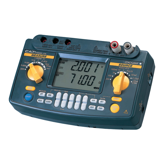
2. Names and Functions of Parts IM CA71-E... - Page 17 2. Names and Functions of Parts Front Panel 1 POWER Key Turns on/off the power supply. 2 LIGHT Key Turns on/off the backlight of the LCD. MEASURE Mode – Functions for Measurement 3 DC Voltage, AC Voltage, Resistance and Pulse Input Terminals Serve as H (positive) and L (negative) input terminals when you mea- sure DC voltage, AC voltage, resistance, and pulse signals.
- Page 18 2. Names and Functions of Parts 8 MEASURE OFF Key Turns on/off the MEASURE mode. Turning off the mode causes the measured value shown on the LCD to disappear. If the MEASURE mode is not in use and therefore turned off, the power to the measure- ment circuit within the calibrator is also turned off.
- Page 19 2. Names and Functions of Parts 17 n/m Key Turns on/off the divided output function ( n/m ). Output Setting Keys Set the output value of a source function. Each pair of keys corresponds to each digit of the reading, thus increasing/decreasing the digit in units of 1s.
- Page 20 2. Names and Functions of Parts 24 I/O Port Cover Open this cover to connect the RS232 communication cable (P/N: 91017). (CA71 only) LCD Unit a. Measured value b. Setpoint for source c. HOLD indicator Indicates the on-screen measured value is in a hold state. d.
- Page 21 2. Names and Functions of Parts k. Battery replacement indicator Shows the battery level in three steps according to the level of remain- ing electricity. RJON indicator Indicates reference junction compensation is active when thermoelectromotive force is being sourced. The thermoelectromotive force output when this indicator is off represents the 0°C-based output.
-
Page 22: Before Starting Source/Measurement
3. Before Starting Source/Measurement Operating Precautions Precautions for Safe Use of the Instrument When using the instrument for the first time, be sure to read the instruc- tions given on pages iv and v of the section, “Precautions for Safe Use of the Instrument.”... - Page 23 3. Before Starting Source/Measurement Before cleaning the instrument’s case or operation panel disconnect the power cord plug from the wall outlet if you are using an AC adapter. Use a soft, clean cloth soaked in water and tightly squeezed to gently wipe the outer surfaces of the instrument.
- Page 24 3. Before Starting Source/Measurement NOTE • Use the instrument under the following environmental conditions if precise source or measurement is your requirement: ± ° Ambient temperature range: 23 C; ambient humidity range: 20 to 80% RH (non-condensing) ° When using the instrument within a temperature range of 0 to 18 C or 28 to °...
- Page 25 3. Before Starting Source/Measurement Step 1: Remove the lead cables and AC adapter and turn off the cali- brator before you begin installing batteries. Step 2: Remove the battery holder cover by sliding it in the direction indicated by →OPEN. Step 3: Install four AA-size (LR6) alkaline batteries in the battery holder with their positive and negative electrodes positioned correctly as indicated on the holder.
- Page 26 Do not use any AC adapter other than the dedicated AC adapter from Yokogawa M&C Corporation. Step 1: Make sure the calibrator is turned off. Step 2: Insert the plug of the optional AC adapter into the AC adapter connection jack.
- Page 27 3. Before Starting Source/Measurement Turning On/Off MEASURE Mode Pressing the key after power-on turns off the MEASURE mode. • If the MEASURE mode is not needed and therefore turned off, power to the measurement circuit is also turned off within the cali- brator.
- Page 28 3. Before Starting Source/Measurement Turning On/Off the Backlight The LCD can be back-lit. Pressing the key turns on the backlight, while pressing the key once again turns it off. This feature makes it easier for you to view the LCD when operating the calibrator in dark places or when carrying out source or measurement.
-
Page 30: Source
4. Source From the calibrator, you can source a DC voltage, DC current, SINK current, resistance, thermocouple, RTD, frequency or pulse signal. WARNING To avoid electrical shock, do not apply any voltage above 30 V to the output terminals. Always use the calibrator in locations with a voltage to ground below 30 V. -
Page 31: Connecting Cables To Terminals
4.1 Connecting Cables to Terminals 4.1 Connecting Cables to Terminals For DC voltage, DC current, thermocouple or pulse output Step 1: Connect the red lead cable for source (P/N: 98020) to the H output terminal and the black lead cable to the L output termi- nal. -
Page 32: Sourcing Dc Voltage, Dc Current Or Sink Current Signal
4.2 Sourcing DC Voltage, DC Current or SINK Current Signal 4.2 Sourcing DC Voltage, DC Current or SINK Current Signal 4.2.1 Sourcing DC Voltage or DC Current Signal Step 1: Using the Function selector switch, select the desired source function from Step 2: The LCD shows the default value and unit of the source func- tion. -
Page 33: Ma Function
4.2 Sourcing DC Voltage, DC Current or SINK Current Signal If either of the following cases applies, the protection circuit works to turn off the output. • The output terminals or the lead cables for source connected to the output termi- nals are short-circuited or an excessive load current has flowed through the cables when a voltage is being output. -
Page 34: Ma Sink Function
4.2 Sourcing DC Voltage, DC Current or SINK Current Signal 4.2.3 20 mA SINK Function The 20 mA SINK function can draw a preset amount of current from an external voltage source to the H terminal. Thus, you can use the cali- brator in a loop test, for example, as a simulator for two-wire transmit- ters. -
Page 35: Using As 24-V Loop Power Supply
4.2 Sourcing DC Voltage, DC Current or SINK Current Signal 4.2.4 Using As 24-V Loop Power Supply A maximum load current of 22 mA can be drawn from the calibrator by selecting the 30 V range and setting the sourced voltage to 24 V. With this function, you can use the calibrator as a loop power supply in place of the distributor in a two-wire loop, as shown in the following figure. -
Page 36: Sourcing Resistance Or Rtd Signal
4.3 Sourcing Resistance or RTD Signal 4.3 Sourcing Resistance or RTD Signal • The calibrator sources a resistance signal by 1) receiving the resis- tance-measuring current I supplied from the device being calibrated, such as a resistance meter or RTD thermometer, and 2) delivering the voltage V = R ×... - Page 37 4.3 Sourcing Resistance or RTD Signal Step 1: Using the function selector switch, select Step 2: Using the key, select the range. Pressing the cycles through the 400 Ω, PT100 and JPT100 options. Step 3: Set the output value digit by digit using each pair of keys.
-
Page 38: Sourcing Thermocouple (Tc) Signals
4.4 Sourcing Thermocouple (TC) Signals 4.4 Sourcing Thermocouple (TC) Signals 4.4.1 When RJ Sensor Is Used (Making Use of Refer- ence Junction Compensation) To calibrate a device with built-in reference junction temperature com- pensation by sourcing a thermoelectromotive force with the calibrator without using any external 0°C reference junction compensation means, use the optional RJ sensor (P/N: B9108WA). - Page 39 4.4 Sourcing Thermocouple (TC) Signals Step 6: Pressing the key causes the indicator on the LCD to change from . A thermoelectromotive force based on the temperature detected by the RJ sensor develops be- tween the output terminals. Step 7: To turn off the output, press the key once again.
-
Page 40: When No Rj Sensor Is Used
4.4 Sourcing Thermocouple (TC) Signals 4.4.2 When No RJ Sensor Is Used From the output terminals, the calibrator sources a thermoelectromotive force corresponding to the preset temperature of a selected thermo- couple. The thermoelectromotive force is sourced with reference to 0°C. -
Page 41: Sourcing Pulse Signals
4.5 Sourcing Pulse Signals 4.5 Sourcing Pulse Signals You can source a preset type of continuous pulse train, a pulse signal with a preset frequency, or the preset number of pulses. Amplitude setpoint Continued Frequency-based signal Source of number of pulses n = Preset number OFF ON of pulses... - Page 42 4.5 Sourcing Pulse Signals Step 5: Set the output value digit by digit using each pair of output setting keys. Each pair of keys corresponds to each digit of the LCD reading. Each press of the key increases or decreases the digit. Increasing the digit from 9 or decreasing it from 0 causes the digit to overflow or underflow, allowing you to set the output value without interruption.
-
Page 43: Sourcing The Preset Number Of Pulses (Pulse Cycle)
4.5 Sourcing Pulse Signals 4.5.2 Sourcing the Preset Number of Pulses (Pulse Cycle) Step 1: Using the function selector switch, select . The LCD shows the default frequency Step 2: Using the key, set the frequency range. Each press of key cycles through the 500.0 Hz, 1000 Hz and 10 kHz options. - Page 44 4.5 Sourcing Pulse Signals Step 7: Set the number of pulses value digit by digit using each pair of output setting keys. Each press of the increases or decreases the digit. Increasing the digit from 9 or decreasing it from 0 causes the digit to overflow or under- flow, allowing you to set the output value without interruption.
-
Page 45: Using The Contact Output
4.5 Sourcing Pulse Signals 4.5.3 Using the Contact Output You can turn on or off the output terminals. This setting is possible for both the mode of sourcing a continuous pulse train and the mode of sourcing a given number of pulses. An FET is used as the contact switching device. - Page 46 4.5 Sourcing Pulse Signals Step 7: Pressing the key causes the indicator on the LCD to change from . The output terminals turn on and off at the preset frequency. Step 8: To turn off the output, press the key once again. The appears on the LCD and the output terminals are open-cir- cuited.
-
Page 47: Divided Output Function (N/M)
4.6 Divided Output Function ( n/m ) 4.6 Divided Output Function ( n/m ) The divided output function ( n/m ) outputs a value n/m times the setpoint of a voltage, current, resistance, thermocouple or RTD signal. Thus, the output value is defined as: Output value = Main setpoint ×... - Page 48 4.6 Divided Output Function ( n/m ) Step 6: Pressing the key causes the indicator on the LCD to change from . The calibrator sources a (main setpoint) × ( n/m ) signal between the output terminals for each range selected. Step 7: To turn off the output, press the key once again.
-
Page 49: Sweep Function
4.7 Sweep Function 4.7 Sweep Function The sweep function varies the output in a linear manner. For further details, see Section 7.1, “Sweep Function.” 4.8 Auto Step Function The auto step function varies the output in a step-by-step manner. For further details, see Section 7.2, “Auto Step Function.”... - Page 50 4.7 Sweep Function • In approximately 10 seconds, the temperature monitor function automatically re- turns to the initial normal setting mode. • The reading of internal temperature may become higher than the room’s tempera- ture because of a temperature rise within the calibrator. With an external RJ sen- sor, it is possible to measure the room’s temperature more precisely.
-
Page 52: Measurement
5. Measurement WARNING In an application where the calibrator is used together with the supplied lead cables for measurement, the allowable voltage to ground of the input termi- nals is 300 V maximum. To avoid electrical shock, do NOT use the calibrator at any voltage exceeding the maximum voltage to ground. -
Page 53: Connecting Cables To Terminals
5.1 Connecting Cables to Terminals 5.1 Connecting Cables to Terminals For DC voltage, AC voltage, resistance, frequency or pulse signal Step 1: Connect the red lead cable for measurement (P/N: RD031) to the H input terminal and the black lead cable to the L input terminal. - Page 54 5.1 Connecting Cables to Terminals CAUTION • Before connecting the calibrator to the device under test, cut off the power to the device. • Do not apply any voltage or current exceeding the allowable voltage (300 V) or current (120 mA). Otherwise, there will be a danger of not only damage to the instrument but also personal injury due to electrical shock.
-
Page 55: Measuring 300 V Ac-Range Voltage, Dc Voltage, Ac Voltage Or Dc Current
5.2 Measuring 300 V AC-range Voltage, DC Voltage, AC Voltage or DC Current 5.2 Measuring 300 V AC-range Voltage, DC Voltage, AC Voltage or DC Current 5.2.1 Measuring 300 V AC-range Voltage CAUTION If you make a mistake in wiring or in the operating procedure in this measure- ment task, there will be a danger of not only damage to the instrument but also personal injury due to electrical shock. - Page 56 5.2 Measuring 300 V AC-range Voltage, DC Voltage, AC Voltage or DC Current Replacing the Fuse The current input protection fuse in the mA/3WIRE terminal is housed inside the fuse holder (labeled FUSE) on one side panel of the calibra- tor.
-
Page 57: Measuring Resistance Or Rtd (Ca71 Only) Signal
5.3 Measuring Resistance or RTD (CA71 only) Signal 5.3 Measuring Resistance or RTD (CA71 only) Signal Step 1: Using the function selector switch, select Step 2: Using the key, select the range. Pressing the key cycles through the 400 Ω, Pt100 and JPt100 options. •... -
Page 58: Measuring Temperature With Thermocouple (Tc) - Ca71 Only
5.4 Measuring Temperature with Thermocouple (TC) - CA71 only - 5.4 Measuring Temperature with Thermo- couple (TC) - CA71 only - NOTE Use the terminal adapter in locations where any voltage higher than 30 V will never be imposed on the measuring circuit. Step 1: Using the function selector switch, select Step 2: Using the key, select the type of thermocouple. -
Page 59: Measuring Frequency Or Pulses
5.5 Measuring Frequency or Pulses 5.5 Measuring Frequency or Pulses 5.5.1 Operating the Calibrator for Frequency Measure- ment Step 1: Using the function selector switch, select Step 2: Using the key, select 100 Hz, 1000 Hz or 10 kHz. Pressing the key cycles through the 100 Hz, 1000 Hz, 10 kHz, CPM and CPH options. - Page 60 5.5 Measuring Frequency or Pulses NOTE • If you press the key after the completion of counting while the indicator is lit, the calibrator restarts counting from 0. • If you press the key halfway before the selected time (one minute or one hour) expires, the calibrator stops counting at that moment.
-
Page 62: Memory Functions
6. Memory Functions The built-in memory has the following four functions. With a pair of sourced and measured signal values in a set, the calibrator can handle a maximum of 50 sets of data (hereinafter simply referred to as data) by means of its built-in memory. -
Page 63: Saving Data Into Memory
6.1 Saving Data into Memory 6.1 Saving Data into Memory 6.1.1 Saving Data in the Order of Memory Numbers Step 1: Press the key. The indicator on the LCD turns on. At this point, the indicator shows a memory number immedi- ately following the one most recently used to save data. - Page 64 6.1 Saving Data into Memory ndicates the memory number with which data is already saved. All these are not yet used. (Case I) 01 02 03 04 05 06 07 08 09 10 11 12 13 14 15 16 49 50 Indication when selected MEM No.07 These are not yet used.
-
Page 65: Saving Data By Selecting Desired Memory Number
6.1 Saving Data into Memory 6.1.2 Saving Data by Selecting Desired Memory Num- Step 1: Press the key. The indicator on the LCD turns on. Step 2: Using the pair of key, select the desired memory number (address). Step 3: Pressing the key saves the sourced and measured (currently on-display) signal values at that moment into the area with the selected memory number (address). -
Page 66: Reading Data From Memory
6.1 Saving Data into Memory NOTE • To stop overwriting the data, press the key one time. This cancels sav- ing data, reverting to the original state of being able to save/read data to/ from memory. To cancel the memory mode (saving/reading), press the key one more time. -
Page 67: Clearing Data In Memory
6.3 Clearing Data in Memory 6.3 Clearing Data in Memory 6.3.1 Clearing Data by Selecting Desired Memory Number Step 1: Press the key once. The indicator on the LCD turns on. Step 2: Using the pair of key, select the memory number whose data you want to clear. -
Page 68: Clearing All In-Memory Data Globally
6.3 Clearing Data in Memory 6.3.2 Clearing All In-Memory Data Globally Step 1: Press the key once. The indicator on the LCD turns on. Step 2: Hold down the key for at least five seconds. The LCD shows the alarm indication. Step 3: Pressing the key once again clears all of the data in memory. -
Page 70: Functions Provided By Dip Switch
7. Functions Provided by DIP Switch By configuring the DIP switch, you can use the functions listed below. The DIP switch can be found by removing the battery holder cover at the back of the calibrator. CAUTION Turn off the calibrator before you change the DIP switch configuration. Factory Setting DIP Switch Description... -
Page 71: Sweep Function
7.1 Sweep Function 7.1 Sweep Function The sweep function lets you linearly change the calibrator output as shown in the following figure. The SOURCE ON The SOURCE OFF indication blinks. indication blinks. Setpoint Sourced-value reading Actual output SOURCE ON Press Press key operation (ON) - Page 72 7.1 Sweep Function Step 6: Using the pair of keys, set the upper limit of the signal to be output. The lower limit is set to a value predeter- mined depending on the selected range. Step 7: Pressing the key initiates sweeping and the output value begins to increase.
-
Page 73: Auto Step Function
7.2 Auto Step Function 7.2 Auto Step Function The auto step function automatically changes the variable n of the n/m output in a step-by-step manner, as shown in the following figure, when the divided output function ( n/m ) is selected. Sourced-value reading Setpoint Actual output... - Page 74 7.2 Auto Step Function Step 8: Using each pair of keys, set the value of the de- nominator m and the starting setpoint of the enumerator n . (See Section 4.6, "Divided Output Function ( n/m ), for further details.) The starting setpoint is the minimum of the variable n for auto step operation.
-
Page 75: Selecting The Int Rj Function
7.3 Selecting the INT RJ Function 7.3 Selecting the INT RJ Function The INT RJ function provides reference junction compensation for thermoelectromotive force source in a simplified manner by means of the calibrator's built-in temperature sensor. For more precise refer- ence junction compensation, it is advisable that you use the optional RJ sensor (P/N: B9108WA). -
Page 76: Switch Not Used
7.5 Switch Not Used 7.5 Switch Not Used Although switch 5 (No Use switch) of the DIP has no effect on calibrator operation, the switch should be placed in the OFF (left-side) position. 7.6 Setting the Temp Switch By placing switch 6 (Temp switch) in the ON (right-side) position, you can select °F for temperature readings. -
Page 78: Communication Function - Ca71 Only
8. Communication Function - CA71 only - You can configure the calibrator from a personal computer just as you do with the calibrator's panel keys (except for turning on/off the power, configuring the function selector switch, and setting the communication function). -
Page 79: Setting The Mode
8.2 Setting the Mode 8.2 Setting the Mode Step 1: Press the key while simultaneously holding down the key. The LCD shows in its upper section and either in its lower section. Step 2: Using the pair of keys, select Step 3: Press the key to confirm your mode selection. -
Page 80: Data Format
8.4 Data Format When communication is in progress, the indicator blinks, telling you data is being output. Care must be taken therefore, since the hold function of the MEASURE mode is disabled if you select 8.4 Data Format Data is output from the calibrator in the following format. Source: Function Range... -
Page 81: Commands
8.6 Commands 8.6 Commands Turns the back lighting on and off /queries the current setting. Moves down the “m-th” digit of the sourced setpoint by one digit. Moves up the “m-th” digit of the sourced setpoint by one digit. Enables/Disables the output data header /queries the current setting. Enables/Disables data hold mode/queries the current setting. -
Page 82: Detailed Description Of Commands
8.7 Detailed Description of Commands 8.7 Detailed Description of Commands Turns the back lighting on and off /queries the When normal current setting. condition Syntax for setting BLm<delimiter> Syntax for query ⇒ BL?<delimiter> Response: BLm<delimiter> Description of parameter m=0: Off m=1: On Moves down the “m-th”... - Page 83 8.7 Detailed Description of Commands When normal Queries the measurement function. condition Syntax for query MF? <delimiter> ⇒ Response: MFm<delimiter> Description of parameter m: Measurement function m=0: 300V AC m=1: 100V m=2: 10V m=3: 1V m=4: 100mV m=5: Resistance m=6: Frequency m=7: Current When normal On/Off of measurement/queries the current setting.
- Page 84 8.7 Detailed Description of Commands When normal Outputs measured value. condition/adjustment Syntax for setting ⇒ OD<delimiter> Response: ODabcde<delimiter> Description of parameter <Header section> (Output only when the header is set to “enabled”.) a= V: Voltage A: Current O: Resistance T: Temperature F: Frequency b= DC: Direct current AC: Alternating current...
- Page 85 8.7 Detailed Description of Commands When normal Sets sourced setpoint/queries the current setting. condition Syntax for setting SDm<delimiter> Syntax for query ⇒ SD?<delimiter> Response: SDm<delimiter> Description of parameter m: Sourced setpoint (7 digits) ex. +1.0000 When normal Queries the source function. condition Syntax for query ⇒...
- Page 86 8.7 Detailed Description of Commands Switches between the normal and adjustment When normal modes/queries the current setting. condition/adjustment Syntax for setting SYm<delimiter> Syntax for query ⇒ SY ?<delimiter> Response: SYm<delimiter> Description of parameter m: Mode m=0: Normal mode m=1: Adjustment mode Sets the sourced setpoint/queries the current When adjustment setting.
- Page 87 8.7 Detailed Description of Commands Queries the measurement function. When adjustment Syntax for query ⇒ CMF?<delimiter> Response: CMFm<delimiter> Description of parameter m: Measurement function m=0: AC 300V m=1: 100V m=2: 10V m=3: 1V m=4: 100mV m=5: Resistance m=6: Frequency m=7: Current Queries the source function.
- Page 88 8.7 Detailed Description of Commands Sets divided output ( n/m ) mode/queries the current When normal setting. condition Syntax for setting MNm<delimiter> Syntax for query ⇒ MN?<delimiter> Response: MNm<delimiter> Description of parameter m: n/m mode m=0: Off m=1: On Sets n/m values in divided output ( n/m ) mode/ When normal condition queries the current setting.
-
Page 90: Troubleshooting
9. Troubleshooting Failure Checklist Troubleshoot the cause of any problem using the following checklist. Should the problem persist even if you have taken the given corrective action or if you notice any problem not listed herein, contact the vender from which you purchased the instrument. Problem Corrective Action The LCD shows nothing even if... -
Page 92: Method Of Calibrator Adjustment
10. Method of Calibrator Adjustment To maintain the calibrator at high accuracy levels, it is advisable that the calibrator be calibrated once a year. If the calibrator needs to be readjusted, follow the procedure described below. For a service of cali- bration or readjustment, contact the vender from which you purchased the instrument. - Page 93 10.1 Calibration Standard Selection and Environmental Measurement Functions Function Range Standard’s Measuring to Be to Be Accuracy Remarks Range Name Adjusted Adjusted ±(0.0025% + 1 µV) 100 mV 100 mV ±(0.0025% + 20 µV) ±(0.0025% + 0.2 mV) 10 V 10 V High-precision ±(0.005% + 2 mV)
-
Page 94: Adjusting Source Functions
10.2 Adjusting Source Functions 10.2 Adjusting Source Functions Table 10.1 Adjustment Points of Source Functions Adjustment Points Range Remarks CAL 0 CAL FS 100 mV 100 mV 10 V 10 V 30 V 30 V See the figure below. 20 mA 20 mA See the figure below. - Page 95 10.2 Adjusting source Functions Step 4: Conform that the symbol is appearing on the LCD. Step 5: Read the calibrator output on the calibration standard. Then, using the lowest-order pair of keys, adjust the read- ing so that it matches the given CAL 0 adjustment setpoint in Table 10.1.
- Page 96 10.2 Adjusting source Functions With the CAL mode selected, press the key while holding down the key. This key operation cancels the CAL mode (the same key operation as for selecting the CAL mode). You can use the same key operation to cancel the CAL mode during adjustment, before saving to memory.
-
Page 97: Adjusting Measurement Functions
10.3 Adjusting Measurement Functions 10.3 Adjusting Measurement Functions Table 10.2 Adjustment Setpoints of Measurement Functions Adjustment Setpoint Range Remarks CAL 0 CAL FS DC 100 mV – 100 mV DC 1 V – DC 10 V – 10 V DC 100 V –... - Page 98 10.3 Adjusting Measurement Functions Step 4: Apply the CAL FS adjustment setpoint input of each range in Table 10.2 from the calibration standard to the H and L input terminals of the calibrator. Step 5: Pressing the key confirms the CAL FS adjustment setpoint.
- Page 99 10.3 Adjusting Measurement Functions Ω 10.3.2 Adjusting AC Voltage and Resistance (400 Ranges Step 1: Press the key while simultaneously holding down the key. The LCD shows Step 2: Pressing the highest-order key causes the LCD to show Step 3: Pressing the key enters the measurement CAL mode.
-
Page 100: Notes On The Adjustment Of Temperature Ranges - Cal71 Only
10.3 Adjusting Measurement Functions Step 9: The 0 and FS symbols stop blinking, causing the calibrator to return to the state discussed in step 4. Using the measure- ment range setting rotary switch, select the next range. By repeating steps 4 to 8, you can adjust the measurement func- tion assigned to that range. -
Page 102: Using Accessories
11. Using Accessories When attaching accessories to the calibrator, refer to the following fig- ure. When connecting the included terminal adapter, make sure the adapter is positioned in the correct orientation. Terminal adapter (99021) WARNING The allowable voltage to ground when the included terminal adapter is attached to the input terminals is 30 Black Black... -
Page 104: Specifications
12. Specifications (1) Signal sourcing unit range and accuracy (for both CA51 and CA71) ±(setting percentage plus µV, mV, mA, Ω or °C) Parameter Reference Range Accuracy (23±5°C per year) Resolution Remarks ±(0.02% + 15 µV) 10 µV 100 mV -10.00–110.00 mV ±(0.02% + 0.1 mV) 0–1.1000 V... - Page 105 12. Specifications (2) Measurement unit range and accuracy (for both CA51 and CA71) Accuracy: ±(reading percentage plus µV, mV, µA, Ω or dgt (digit)) Parameter Reference Range Accuracy (23±5°C per year) Resolution Remarks ±(0.025% + 20 µV) 10 µV 100 mV 0–±110.00 mV Input resistance: 10 MΩ...
- Page 106 12. Specifications General specifications (for both CA51 and CA71) Signal sourcing unit response time Approximately 1 second (time between start of voltage change and when voltage enters accuracy range) Signal sourcing unit voltage limiter Approximately 32 V Signal sourcing unit current limiter Approximately 25 mA Output = setting ×...
- Page 107 12. Specifications Approximately 190 × 120 × 55 mm External dimensions (WHD) Weight Approximately 730 g (including batteries) Standard accessories All of the following are included: Lead cables for source (one red, two black): 98020 Lead cables for measurement (one red, one black): RD031 Carrying case: 93016 Terminal adapter for CA71: 99021...
- Page 108 YOKOGAWA CORPORATION OF AMERICA (U.S.A.) Phone: 1-770-253-7000 Facsimile: 1-770-251-2088 YOKOGAWA EUROPE B. V. (THE NETHERLANDS) Phone: 31-334-64-1611 Facsimile: 31-334-64-1610 YOKOGAWA AMERICA DO SUL S. A. (BRAZIL) Phone: 55-11-7295-1433 Facsimile: 55-11-5522-5231 YOKOGAWA ENGINEERING ASIA PTE. LTD. (SINGAPORE) Phone: 65-241-9933 Facsimile: 65-241-2606...
Need help?
Do you have a question about the HANDY CAL CA51 and is the answer not in the manual?
Questions and answers