
Subscribe to Our Youtube Channel
Related Manuals for YOKOGAWA AQ1300 Series


Summary of Contents for YOKOGAWA AQ1300 Series
- Page 1 User’s Manual AQ1300 Series 1G/10G ETHERNET Multi Field Tester IM AQ1300-01EN 6th Edition...
- Page 2 Thank you for purchasing the AQ1300 Series 1G/10G ETHERNET Multi Field Tester. This user’s manual explains the features, operating procedures, and handling precautions of the AQ1300 Series. To ensure correct use, please read this manual thoroughly before operation. Keep this manual in a safe place for quick reference in the event that a question arises.
- Page 3 Revisions 1st Edition: November 2009 2nd Edition: March 2010 3rd Edition October 2010 4th Edition June 2012 5th Edition March 2013 6th Edition June 2014 IM AQ1300-01EN...
-
Page 4: Conventions Used In This Manual
Conventions Used in This Manual Notes The notes and cautions in this manual are categorized using the following symbols. Improper handling or use can lead to injury to the user or damage to the instrument. This symbol appears on the instrument to indicate that the user must refer to the user’s manual for special instructions. -
Page 5: Table Of Contents
Contents Conventions Used in This Manual ....................iii Chapter 1 Features Interaction between the Setup Software and the AQ1300 Series ........1-1 Test Menu (Top Menu) ...................... 1-2 Test Modes ........................1-3 Test Configurations ......................1-4 Layer 1 Control ......................... 1-7 Transmission Features ..................... - Page 6 Contents Chapter 5 Automatic (Remote Control) Test Settings (Auto(Remote)) Selecting a Setup File ...................... 5-1 Setting Up a Test ......................5-3 Configuring Link Settings ....................5-4 Configuring the Master Settings ..................5-6 Configuring the Slave Settings ..................5-13 Switching between the Master and Slave Settings ............5-15 Controlling the Other Device Remotely ................
- Page 7 Contents Chapter 9 Performing RFC2544 Measurements (AQ1300 Option) Starting Measurement ...................... 9-1 Displaying the Test Results ....................9-4 Displaying Throughput Test Results ................. 9-6 Displaying Latency Test Results ..................9-8 Displaying Frame Loss Rate Test Results ..............9-10 Displaying Back to Back Test Results ................9-12 Displaying Packet Jitter Test Results................
- Page 8 14.3 Configuring Power Save Settings ................... 14-3 14.4 Configuring Network Settings ..................14-4 14.5 Resetting the AQ1300 Series to Its Factory Default Settings ......... 14-6 14.6 Setting the Top Menu Type ..................... 14-7 14.7 Using the Utility Menu ....................14-9...
-
Page 9: Chapter 1 Features
Create a test scenario with the setup software PC application, and then save the scenario to a setup file. Upload the saved setup file to the AQ1300 Series (AQ1300 and AQ1301), and then use the test scenario to perform a test. The test results are saved to a result file. Use the PC to download the result file, and then use the setup software to print a report. -
Page 10: Test Menu (Top Menu)
• LT (link trace): Link check between network devices System Select System to configure the AQ1300 Series system settings. Language, Beep, USB Function, Date & Time Set, Power Save mode, Network Setup, Factory Setting, Product Info. display, Selftest, Version Up... -
Page 11: Test Modes
You can also use traceroute testing to check the route to the target (the other device). BERT Mode In this mode, bit error rate testing is performed. The AQ1300 Series inserts a pseudo-random pattern (PN15) into the payload of the Tx frame and checks whether or not bit errors are occurring between itself and the other device. -
Page 12: Test Configurations
Traffic Network Traffic Loopback Traffic Test (Latency measurement) The other device is set to Loopback Test mode so that the AQ1300 Series receives the traffic that it sends, and the AQ1300 Series measures the network round-trip latency. Other device Loopback •... - Page 13 You can also use traceroute testing to check the route to the target (the other device). Other device Network ICMP emulation Traceroute BERT Test The AQ1300 Series performs a bit error rate test. Other device PN pattern BERT Network BERT PN pattern...
- Page 14 1.4 Test Configurations Inband Remote This is the test configuration for an Auto(Remote) test. You can use dedicated remote commands to perform testing on the slave, change settings, and acquire measurement results. Because the slave device can be controlled remotely, a single person can perform this test.
-
Page 15: Layer 1 Control
The AQ1300 Series can transmit LF and RF signals consecutively (start/stop). Also, when Manual has been selected in the Test menu, the AQ1300 Series can automatically send an RF signal upon linkdown detection or LF signal reception. RxLF (Local Fault reception) Detection: Four or more sequence columns that indicate LF at an interval less than 128 columns. - Page 16 This feature is supported in firmware version (FW Ver.) R1.08.01.001 and later. 66B Sync hi-ber Detection/Clear When the interface is XFP, the AQ1300 Series detects and clears 66B Sync hi-ber on the basis of the following conditions when signal reception is in a sync (block lock) state as defined in IEEE802.3.
-
Page 17: Transmission Features
Transmission Features Transmission Load Configuration When the test mode is Traffic Test, QoS Test, or BERT, you can set the transmission load by setting the Tx rate and the Tx mode. When the mode is Traffic Test or BERT, you can define a single frame. In QoS test mode, you can define up to eight frames and assign them to the various transmission channels. - Page 18 1.6 Transmission Features If the burst transmission interval determined by the value you set for Burst Number is greater than the value you set for Interval, the AQ1300 Series will transmit frames at a constant rate without any idle condition.
- Page 19 1.6 Transmission Features Tx Frame Definition For the Tx frame definition, in addition to basic frame editing, you can also set the payload, variable field setting, error addition, etc. Frame Editing When Manual has been selected in the Test menu, you can edit the following frames. •...
- Page 20 • Variable range: 64 to 9999 bytes When Test Interface is set to SFP(FE), the sending and receiving of frames that exceed 2048 bytes in length is outside of the AQ1300 Series guaranteed operating range. Automatic Checksum Calculation This feature guarantees the L3 header checksum when Manual has been selected in the Test menu, field variation is enabled, and the variable field has been set to a field within the L3 header checksum (IPv4 header) computation range.
- Page 21 1.6 Transmission Features Test Tags When you are using two AQ1300 Series in a two-way or loopback test configuration, you can attach test tags for analysis to the Tx frames. Test tags are inserted immediately before the Tx frame FCS.
- Page 22 1.6 Transmission Features Transmitting by QoS Channel When Manual has been selected in the Test menu and the test mode is QoS test, you can specify different frames, frame lengths, and transfer rates for each channel and send the frames separately. When Auto or Auto(Remote) has been selected in the Test menu and the test mode is QoS test, you can specify different QoS values, frame lengths, and transfer rates for each channel and send the frames separately.
-
Page 23: Reception Features
Latency Measurement If you set the other device to Loopback Test mode, the AQ1300 Series can insert a timestamp in a Tx frame and measure the latency by determining the difference between the timestamp and the time that the frame comes back. - Page 24 Reorder packets are not counted as loss packets. Max Burst Loss Consecutive frames that the AQ1300 Series is unable to receive are counted as burst loss packets. The Max Burst Loss number represents the maximum burst loss value. 14 15 16...
- Page 25 1.7 Reception Features Reorder Packet Frames that are received out of the order that they were sent in are counted as reorder packets. The Reorder Packet number represents the total number of reorder packets. 9 10 12 13 14 15 16 18 19 Wrong order Loss Packet:...
- Page 26 1.7 Reception Features Payload Error Measurement Using the (16-bit) payload CRC data in fields in Rx frame test tags, the AQ1300 Series can check for payload errors between itself and the other device. BER Measurement By inserting a pseudo-random pattern (PN15) into the fill pattern data area of a Tx frame payload and then sending the Tx frame to the other device, the AQ1300 Series can perform a BER measurement to check for device errors.
-
Page 27: Statistics
Statistics List of Statistics Group Name Display Display Digits Condition Common Acquisition Time YYYY/MM/DD hh:mm:ss Measurement Duration hh:mm:ss Link Link Status Up to 22 characters Laser Off Count 16-digit integer XFP or SFP interface Linkdown Count 16-digit integer Tx Freq Deviate(ppm) +/- sign and 1 digit after the decimal point Rx Freq Deviate(ppm) +/- sign and 1 digit after the decimal point... - Page 28 1.8 Statistics Group Name Display Display Digits Condition Latency Max IFG(us) Integer part: 10 digits, fractional part: 1 digit Min IFG(us) Integer part: 10 digits, fractional part: 1 digit Avg IFG(us) Integer part: 10 digits, fractional part: 1 digit Max IFG(bit) Integer part: 16 digits Min IFG(bit) Integer part: 16 digits...
- Page 29 1.8 Statistics E-OAM Test Statistics Group Name Display Display Digits Conditions LoopBack(LB) Test Count 16-digit integer When the mode is LB test Loss Count 16-digit integer Loss Rate Integer part: 3 digits, fractional part: 1 digit Max Response Time(ms) Integer part: 3 digits, fractional part: 3 digits Min Response Time(ms) Integer part: 3 digits, fractional...
- Page 30 This feature is supported in firmware version (FW Ver.) R1.08.01.001 and later. 66B Sync Error Count Indicates the number of times the AQ1300 Series detected blocks whose sync header (2 bits) is 00 or 11 when signal reception is in a sync (block lock) state as defined in IEEE802.3.
- Page 31 1.8 Statistics Error Frame Indicates the total number of frames that have been sent with a CRC, undersize, oversize, or symbol error CRC Error Indicates the number of frames that have been sent with a CRC error attached to FCS Undersize Error Indicates the number of transmitted frames that have been larger than 17 bytes but smaller than 64 bytes (not including the preamble but including the FCS)
- Page 32 CRC Error Indicates the number of frames in which FCS errors were detected. The AQ1300 Series detects errors by comparing the CRC values calculated from the received frames to the FCS (Frame Check Sequence) values in the received frames. Undersize Indicates the number of undersized frames.
- Page 33 The AQ1300 Series detects errors by comparing the CRC values calculated from the payload in received frames to the CRC values for payload checking that is included in the received frames.
- Page 34 1.8 Statistics Rate(%) Indicates the data reception rate (as a percentage) for each QoS channel Rate(fps) For each QoS channel, this item indicates the number of frames that have been received normally in a single second Rate(bps) For each QoS channel, this item indicates the number of bits in the frames that have been received normally in a single second Peak Rate Indicates the highest rate detected during measurement (as a percentage, in fps, or in bps) for each...
- Page 35 AQ1300 Series synchronizes with the received frame at least once (when the BERT target byte is not zero). The AQ1300 Series detects errors by comparing the CRC values calculated from the payload in received frames to the CRC values for payload checking that is included in the received frames.
- Page 36 1.8 Statistics LoopBack (LB) Group Test Count Indicates the number of sent LBM frames Loss Count Indicates the number of failed attempts Loss Rate Indicates the percentage of frames that have been lost as a result of timeouts Max Response Time(ms) Indicates the maximum response time Min Response Time(ms) Indicates the minimum response time...
- Page 37 1.8 Statistics Through CCM Count Indicates the number of received CCM frames whose maintenance domain level (MD level) is higher than the MD level of the AQ1300 Series Unexpected MEP Count Indicates the number of unexpected MEP detections This is detected when the maintenance domain level (MD level) and domain name in the received CCM frame are correct but the MEP ID of the other network device (MEP) is different from the “target...
-
Page 38: Emulation
• If an ARP request is received while transmission is paused, an ARP reply is sent after transmission is resumed. • If transmission is paused and the AQ1300 Series is waiting to send an ARP reply and a normal test frame, after transmission resumes, the AQ1300 Series will send the ARP reply first and then the normal test frame. - Page 39 (Acquisition is performed before measurement starts. Afterwards, the statistics are cleared and measurement starts.) • The AQ1300 Series waits for a reply after it sends an ARP packet. The timeout value is 1 second. The AQ1300 Series will try again after timing out.
- Page 40 If the test menu is set to Manual and the test layer is IPv4, this feature automatically generates multiple MAC addresses from the VLAN ID or IP address information and make the AQ1300 Series emulate multiple hosts in the VLAN.
- Page 41 • If an NS is received while transmission is paused, an NA is sent after transmission is resumed. • If transmission is paused and the AQ1300 Series is waiting to send an NA, an insert frame, and a normal test frame, after transmission resumes, the AQ1300 Series will send the insert frame, the NA, and then the normal test frame.
- Page 42 (Acquisition is performed before measurement starts. Afterwards, the statistics are cleared and measurement starts.) • The AQ1300 Series waits for a reply after it sends an NS (neighbor solicitation) packet. The timeout value is 1 second. The AQ1300 Series will try again after timing out.
-
Page 43: Ping And Traceroute Testing
1.10 Ping and Traceroute Testing Ping Test You can perform IPv4/IPv6 ping testing. • Destination: A single host • Interval: 1 ms, 10 ms, 100 ms, 1 s • Tx Mode: Frames, Time, Continuous • Frame Length IPv4: 64 (+up to two VLAN stacks) to 9999 bytes IPv6: 84 (+up to two VLAN stacks) to 9999 bytes Unsupported Ping Frames •... -
Page 44: Logging Statistics
1.11 Logging Statistics When Manual has been selected in the Test menu, you can log statistics on the AQ1300 Series. The logged data is saved to a CSV file. • Logging interval: • Logging time: Specify the time in seconds up to 4 hours (14400 seconds), or select 12, 24, 48, or 72 hours. -
Page 45: Simple Test Creation And Execution
You can execute tests by loading the setup file that you created with the setup software onto the AQ1300 Series and selecting the configured test items. Consecutive Test Item Execution You can execute registered test items consecutively. -
Page 46: Displaying Test Pass/Fail Results
You can set the pass/fail conditions in the setup software for each test mode. You can only use the AQ1300 Series to display the pass/fail conditions, not to set them. You can set whether or not to perform pass/fail judgment. -
Page 47: File
1.14 File The AQ1300 Series and the setup software use the following files. File Type File Format Extension AQ1300 Series Setup Software (AQ1300 and AQ1301) Save Load Save Load Setup file Binary Management file Binary .dmf Statistical result file Binary... -
Page 48: Optical Power Measurement (Aq1300 Option)
1.15 Optical Power Measurement (AQ1300 Option) On models with the /SPML option, when OPM has been selected in the Test menu, you can measure optical power. Wavelength range 850, 1300, 1310, 1490, 1550, 1625, 1650 nm Measurement range –60 to +10 dBm Modulation mode CW, 270 Hz, 1 kHz, 2 kHz You can select the modulation frequency of the incident rays from a list. -
Page 49: Rfc2544 Measurement (Aq1300 Option)
(at the initial rate) over the specified measurement time (the test duration). During the test duration, if a loss is detected, the rate is automatically decreased. The AQ1300 Series performs another measurement to detect whether a loss occurs at this new rate. If a loss is detected, the same operations are repeated. - Page 50 This is the length of one measurement for detecting losses. Number of Trials The number of times that the AQ1300 Series will perform the series of operations from the start of measurement to the point where the rate converges to the specified value. In one trial, frame signals of the preset frame lengths are used to perform the loss detection measurements.
- Page 51 The delay is the average of the values from all the trials. Test Rate The traffic rate that the AQ1300 Series uses to measure the delay. You can change the test rate value. If you have already performed the throughput measurement, you can set the traffic rate to the measured throughput result.
- Page 52 Number of Trials The number of times that the AQ1300 Series will perform the series of operations from the start of measurement to the point where the rate at which losses are no longer detected is found. In one trial, frame signals of the preset frame lengths are used to perform the frame loss rate measurements.
- Page 53 Index You can perform pass/fail judgments by setting the threshold on the number of burst frames (the lower limit on the number of frames) on the AQ1300 Series in advance.If the value falls below the threshold, a fail judgment occurs.
- Page 54 The delay variation is the average of the values from all the trials. Test Rate The traffic rate that the AQ1300 Series uses to measure the delay variation. You can change the test rate value. If you have already performed the throughput measurement, you can set the traffic rate to the measured throughput result.
- Page 55 60 classes. The AQ1300 Series sets the percentile value to the largest value that is within the class that contains the value that corresponds to the threshold value.
-
Page 56: Vlan Test
Reception and Analysis The AQ1300 Series compares the list of the VLAN IDs that are planned to be received with the actual received VLAN IDs and displays the result. You can edit VLAN ID lists on the AQ1300 Series or load VLAN ID definition files into the VLAN ID list. -
Page 57: Telnet Remote Control
1.18 Telnet Remote Control The AQ1300 Series can be controlled remotely as a Telnet server. This feature is supported in auto test or auto(remote) test modes. For details, see the Communication Interface User’s Manual, IM AQ1300-17EN. Index 1-49 IM AQ1300-01EN... -
Page 58: E-Oam Test
The E-OAM test checks the connection of network devices that are connected to a network segment configured with an E-OAM router. In this test, the AQ1300 Series sends E-OAM frames and checks whether response frames are returned from devices connected at the far end of the network (MEP;... - Page 59 When LOC Is Detected When a loss of continuity is detected (CCM frame is not received), if the auto RDI transmission is enabled on the AQ1300 Series, an RDI frame is sent to the network device at the destination address.
- Page 60 1.19 E-OAM Test LB Reply If LB reply is enabled in the AQ1300 Series emulation settings, when an LBM frame addressed to the AQ1300 Series is received, an LBR frame is sent to the network device at the destination address. LT Execution...
-
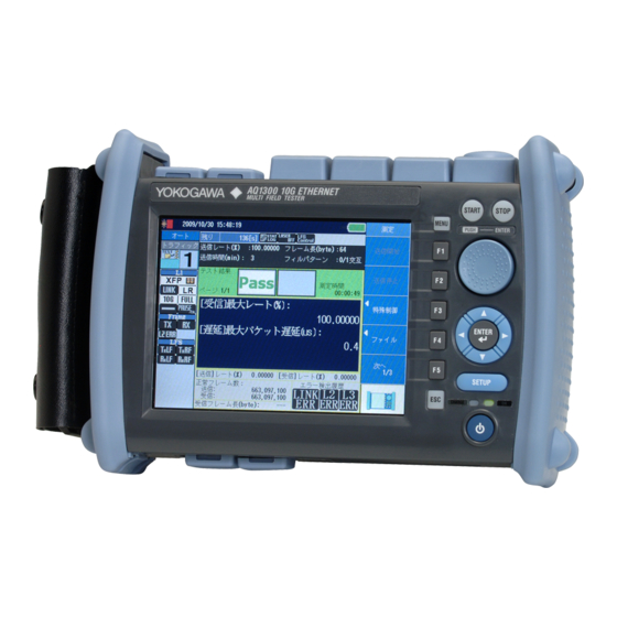
Page 61: Chapter 2 Screen Explanations
Chapter 2 Screen Explanations Measurement Screens (Common Items) This section explains the common items in the measurement screens. Screen during Measurement Test information Title bar Measurement status Summary Test results Error History “over” is displayed when the number of detected errors exceeds 999. - Page 62 2.1 Measurement Screens (Common Items) Title Bar Simple Optical Power Monitor When the interface is XFP or SFP, the AQ1300 Series can monitor the received optical power level and indicate it using three levels. Indication Colors Description Black and black...
- Page 63 2.1 Measurement Screens (Common Items) Link Status Indications The link status is indicated. Category Status Name Status Indication Description I/F type The XFP interface is selected. The SFP interface is selected. RJ-45 The RJ-45 interface is selected. Module type The I/F type is XFP, and the module type is SR. The I/F type is XFP, and the module type is LR.
- Page 64 2.1 Measurement Screens (Common Items) Measurement Status Indications The measurement status is indicated. Status Name Status Indication Description Tx time The remaining Tx time/ The remaining time is indicated in seconds. number of frames The remaining number of frames is indicated by a number from 0 to 99999999.
- Page 65 The number of detected errors is cleared when: • Measurement is started • Setup data is loaded • You log in to the AQ1300 Series Test-Mode-Specific Items Different measurement items are displayed for different test modes. For details, see section 2.2.
-
Page 66: Measurement Screens (Test-Mode-Specific Items)
Measurement Screens (Test-mode-specific items) This section explains the test-mode-specific items in the measurement screens. Traffic Test Summary (Tx rate; Tx time, frames, or elapsed time; frame length, fill pattern) Test-mode-specific indications (Rx rate, packet latency) Loopback Test Summary (loopback target) Test-mode-specific indications (none) QoS Test Summary (Tx rate for each channel) - Page 67 2.2 Measurement Screens (Test-mode-specific items) PING Test Summary (destination IP address, Tx interval, number of frames) Test-mode-specific indications (loss count, sequence number, round trip time, packet length, TTL) BERT Summary (Tx rate; Tx time, frames, or elapsed time; frame length) Test-mode-specific indications (bit error rate, bit error, BERT target byte) Index...
- Page 68 2.2 Measurement Screens (Test-mode-specific items) Summary A summary of the settings is displayed, or the addresses are displayed. • Summary: Representative settings are displayed. Test Mode Displayed Items Traffic Test Tx rate; Tx time (when Tx Mode is set to Time), number of frames (when Tx Mode is set to Frames), or elapsed time (when Tx Mode is set to Continuous);...
-
Page 69: Chapter 3 Common Operations
MENU will not appear. • If you press ESC on the first page of a setup menu (Auto, Auto(Remote), Manual, Option, or System), the AQ1300 Series will operate in the same manner as when MENU is pressed. Index IM AQ1300-01EN... - Page 70 3.1 Key, Rotary Knob, and Arrow Key Operations About the Explanations in this Manual In this manual, steps 1 through 3 listed previously and the setup operations in the menu that follows them are written as shown below. Setup Operation Example Press the Manual soft key, the Next 1/2 soft key, and then the File soft key to display the following screen.
- Page 71 3.1 Key, Rotary Knob, and Arrow Key Operations Rotary Knob and Arrow Key Operations This section explains how to operate a menu and the operations to perform when a setup dialog box appears. As an example, we will use the dialog box that appears when you press the System soft key and then the System softkey in the system setup.
- Page 72 3.1 Key, Rotary Knob, and Arrow Key Operations About the Explanations in this Manual In this manual, steps 1 through 4 listed previously and the setup operations in the menu that follows them are written as shown below. Setup Operation Example Press the OPM soft key and then the Setup soft key to display the following screen.
-
Page 73: Entering Strings
Entering Strings After you have selected a setup item and pressed ENTER, a character input dialog box will appear if it is necessary. This section explains the operations that you can perform after the dialog box appears. Entering Strings Using the rotary knob and ENTER, enter a string. The string that you entered appears in the edit screen. - Page 74 3.2 Entering Strings Entering Strings from the History Using the rotary knob and ENTER, select to display the input history screen. Using the rotary knob and ENTER, choose the string that you want to enter. The string appears in the edit screen. Note Entered strings are saved to the input history when you confirm them.
-
Page 75: Chapter 4 Automatic Test Settings (Auto)
Set Action to Load. Select a drive (Internal, USB Memory). Loads the selected file Select a setup file (.sd extension) to File list load. The files that you have created using the setup software or the AQ1300 Series appear. Index IM AQ1300-01EN... - Page 76 4.1 Selecting a Setup File Auto Setup Screen The following screen appears when you select a setup file. Set up the test. ►section 4.2 Configure the test items. ►section 4.4 Configure link and address settings. ►section 4.3 Select a setup file. ►section 4.1 To Auto Setup page 2/2 Displays pass/fail judgment conditions...
- Page 77 Select this item when you want to load a setup file that is not in the setup file list. To create a setup file, you can use the setup software and send the file to the AQ1300 Series, or you can save the settings on the AQ1300 Series.
-
Page 78: Setting Up A Test
Setting Up a Test Procedure Test Setup Screen Follow the procedure in section 4.1 to display the Auto Setup screen. Press the Test Setup soft key to display the following screen. Set the test interface (XFP(10GbE), SFP(GbE), RJ-45). Set the test layer (L2 Test, L3-IPv4 Test, L3-IPv6 Test). -
Page 79: Configuring Link And Address Settings
AQ1300 Series Applies link settings Applies the acquired other device’s link settings to the AQ1300 Series. You can execute this when the measurement interface is RJ-45 or SFP(GbE) and the acquisition status is Finish. Status (Preparing, Finish, Fail) - Page 80 4.3 Configuring Link and Address Settings Source Address Screen Press the Link/Address soft key and then the Source Address soft key to display the following screen. Set the source MAC address. Refer to the MAC Address table. Set the VLAN stack number (None, 1, 2). Configure the VLAN settings (CoS: 0-7, ID: 0-4095, TPID: 0-FFFF).
- Page 81 4.3 Configuring Link and Address Settings VLAN Table Press Refer next to a VLAN address to display the following screen. Select the VLAN CoS and ID from the VLAN table. VLAN table Use the setup software to create this table. IP Address Table Press Refer next to an IP address to display the following screen.
- Page 82 4.3 Configuring Link and Address Settings Gateway Press Refer next to the gateway address to display the following screen. Select to set the gateway manually. Select to automatically set the gateway to xxx.xxx.xxx.1. Select to automatically set the gateway to xxx.xxx.xxx.254. IM AQ1300-01EN...
- Page 83 4.3 Configuring Link and Address Settings Destination Address Screen Press the Link/Address soft key and then the Destination Address soft key to display the following screen. Set the destination MAC address. Refer to the MAC Address table. Set the destination IPv4 address. This setting appears when Test Layer is set to L3-IPv4.
- Page 84 4.3 Configuring Link and Address Settings MAC Address Table Press Refer next to the MAC address to display the following screen. Press this soft key to automatically acquire the destination MAC address. When the test layer is L3-IPv4, MAC Address (ARP) appears. When the test layer is L3-IPv6, MAC Address (NDP) appears.
- Page 85 Select whether or not to use auto negotiation. This setting is valid when Test Interface is set to RJ-45 or SFP(GbE). • Auto: The link between the AQ1300 Series and the device that it is connected to is configured automatically through auto negotiation. • Manual: The link must be configured manually.
- Page 86 Normal, The cable may be defective. It is two-pair cable • Applying Link Settings You can apply the acquired other device’s link settings to the AQ1300 Series. You can do this when the measurement interface is RJ-45 or SFP(GbE) and the acquisition status is Finish.
- Page 87 DHCP. This setting is valid when Test Layer is set to L3-IPv4 Test. • Manual: You must set the source IPv4 address manually. • DHCP: When you press Get IP Address, the AQ1300 Series acquires and sets the source IPv4 address using DHCP.
- Page 88 Select the source IP address from the IP Address table. • Get IP Address: Press this soft key to get the IP address. The AQ1300 Series will acquire an IP address, using DHCP when the test layer is L3-IPv4 or stateless autoconfiguration when the test layer is L3-IPv6.
- Page 89 4.3 Configuring Link and Address Settings Address Type You can switch the address type that is displayed when Switch is set to Master Addr. • MAC address • IP address MAC Address Table Select the destination MAC address from the MAC Address table. •...
-
Page 90: Configuring Test Items
Configuring Test Items Procedure Select Test Item Screen Follow the procedure in section 4.1 to display the Auto Setup screen. Press the Select Test Item soft key to display the following screen. Example with the Default Settings Traffic setup ►section 4.5 Loopback setup ►section 4.6 QoS setup ►section 4.7 PING setup ►section 4.8... - Page 91 Configuring a Traffic Test Procedure Traffic Setup Screen Follow the procedure in section 4.4 to display the Traffic Setup screen. Set the Tx rate (0.00001-100.00000%). Set the Tx mode (Continuous, Frames, Time). Set the (actual) frame length (For L2 and L3-IPv4: No VLAN stacks: 64 (64)-9999 (9999) bytes 1 VLAN stack: 64 (68)-9999 (9999) bytes 2 VLAN stacks: 64 (72)-9999 (9999) bytes...
- Page 92 4.5 Configuring a Traffic Test Tx Rate Table Press Refer next to the Tx rate to display the following screen. Select a Tx rate from the Tx Rate table. Tx Time Table Press Refer next to the Tx time to display the following screen. Select a Tx time from the Tx Time table.
-
Page 93: Configuring A Traffic Test
4.5 Configuring a Traffic Test Frames Table Press Refer next to the number of frames to display the following screen. Select a number of frames from the Frames table. Note All the tables are created on the setup software. Explanation Traffic Setup Screen Tx Rate Set the Tx rate. - Page 94 4.5 Configuring a Traffic Test Variable Frame Length Screen This feature is supported in firmware version (FW Ver.) R1.08.01.001 and later. Range Set the frame length adjustment range. Range: 64 to 9999 bytes Step Set the frame length adjustment step. •...
-
Page 95: Configuring A Loopback Test
Configuring a Loopback Test Procedure Loopback Setup Screen Follow the procedure in section 4.4 to display the Loopback Setup screen. Set the loopback target frames (Source Address, All Frames). Explanation Loopback Target Frame Set the loopback target frames. • Source Address: Only frames from the source address are looped back. •... -
Page 96: Configuring A Qos Test
Configuring a QoS Test Procedure QoS Setup Screen Follow the procedure in section 4.4 to display the QoS Setup screen. Set the Tx mode (Continuous, Frames, Time). Set the QoS test type (Frame_ID, VLAN-ID, VLAN-CoS (when there are VLAN stacks), IPv4-ToS, IPv4- DSCP (when the test layer is L3-IPv4), IPv6-TrafficClass, IPv6-DSCP (when the test layer is L3-IPv6), L4-DP, L4-SP(when... - Page 97 4.7 Configuring a QoS Test Explanation QoS Setup Screen Selecting the QoS Channels to Use You can select up to four QoS channels. QoS Field Select the type of QoS test. Test Type Test Layer Description Notes IPv4 IPv6 Frame_ID The frame number for each QoS channel VLAN-ID The VLAN ID...
-
Page 98: Configuring A Ping Test
Configuring a Ping Test Procedure PING Setup Screen Follow the procedure in section 4.4 to display the PING Setup screen. When Test Layer Is Set to L3-IPv4 Test or L3-IPv6 Test Select this check box to use the destination IPv4 or IPv6 address from the address settings. - Page 99 4.8 Configuring a Ping Test Explanation PING Setup Screen When Test Layer Is Set to L3-IPv4 Test or L3-IPv6 Test Destination IPv4 or IPv6 Address “Use Destination Address” Check Box (Always selected) The destination IPv4 or IPv6 address in the address settings is used (fixed). To specify a different destination IPv4 address, clear this check box.
-
Page 100: Configuring A Bert
Configuring a BERT Procedure BERT Setup Screen Follow the procedure in section 4.4 to display the BERT Setup screen. Set the Tx rate (0.00001-100.00000%). Set the Tx mode (Continuous, Frames, Time). Set the (actual) frame lengths* (For L2 and L3-IPv4: No VLAN stacks: 64 (64)-9999 (9999) bytes 1 VLAN stack: 64 (68)-9999 (9999) bytes 2 VLAN stacks: 64 (72)-9999 (9999) bytes... -
Page 101: Displaying Pass/Fail Judgment Conditions
4.10 Displaying Pass/Fail Judgment Conditions Procedure Pass/Fail Screen Follow the procedure in section 4.1 to display the Auto Setup screen. Press the Pass/Fail soft key to display the following screen. To the next page To the previous page Pass/fail judgment conditions Explanation You can display the pass/fail judgment conditions of the selected test items. -
Page 102: Configuring Options (Auto)
4.11 Configuring Options (Auto) Procedure Advance Setup Screen Follow the procedure in section 4.1 to display the Auto Setup screen. Press the Option (Auto) soft key and then the Advance setup soft key to display the following screen. Set the interval between the pressing of START and the start of transmission (1 to 10 s). - Page 103 • ON: Whenever a test item has finished, you must confirm that you want to proceed before the AQ1300 Series will proceed to the next test item. • OFF: Whenever a test item has finished, the AQ1300 Series will proceed to the next test item without confirmation.
- Page 104 4.11 Configuring Options (Auto) Method for saving continuance test result files You can save each test item of a continuous test to separate files or save multiple test items to a single file. • Single: Each test item is saved to a separate file. This is the conventional method. •...
- Page 105 Select whether or not to try synchronizing with the other device (the address specified as the destination address) when the START or STOP key is pressed. When the START or STOP key is pressed, the AQ1300 Series sends a measurement start or stop packet to the other device at the destination address.
-
Page 106: Chapter 5 Automatic (Remote Control) Test Settings (Auto(Remote))
Appears when you have created a display management file setup file list. using the setup software and sent it to the AQ1300 Series Note In Auto and Auto(Remote) mode, to select a setup file, you can choose to use the latest setup, use the default setup, load a setup file from the file list, or select a setup file from the setup file list. - Page 107 Select this item when you want to load a setup file that is not in the setup file list. To create a setup file, you can use the setup software and send the file to the AQ1300 Series, or you can save the settings on the AQ1300 Series.
-
Page 108: Setting Up A Test
Setting Up a Test Procedure Test Setup Screen Follow the procedure in section 5.1 and then select a setup file to display the following screen. Configure the link settings. ►section 5.3 Select a setup file ►section 5.1 Set the test interface (XFP(10GbE), SFP(GbE), RJ-45). -
Page 109: Configuring Link Settings
Link Setting Acquisition Executes link setting information acquisition Acquires the link setting information of the other device connected to the AQ1300 Series Applies link settings Applies the acquired other device’s link settings to the AQ1300 Series. You can execute this when the measurement interface is RJ-45 or SFP(GbE) and the acquisition status is Finish. - Page 110 Link Setting Acquisition If the interface is SFP(GbE) or RJ-45, you can acquire and display link setting information of the other device (DUT; the device on the user side) connected to the AQ1300 Series. For details, see section 4.3. Index...
-
Page 111: Configuring The Master Settings
Configuring the Master Settings Procedure These are the procedures for configuring the AQ1300 Series when it is the master in Auto(Remote) mode. Source Address Screen Follow the procedure in section 5.3 and then press the Master Setting soft key to display the following screen. - Page 112 5.4 Configuring the Master Settings Destination Address Screen Press the Next soft key to display the following screen. Set the destination MAC address. Refer to the MAC Address table. ►section 4.3 Select from the search list. Manual Setting This soft key is valid when you have selected a destination address from the search list.
- Page 113 5.4 Configuring the Master Settings Connect Screen Press the Connect soft key to display the following screen. ’ Select when you don t want to change the slave settings. Pressing this soft key will open the Auto Setup screen. Select to apply the currently displayed settings to the slave.
- Page 114 5.4 Configuring the Master Settings Auto Setup Screen Press the Complete soft key to display the following screen. Set up the test. ►section 4.2 Configure the test items. ►section 4.4 Configure link and address settings. ►section 4.3 Select a setup file. ►section 5.1 To Auto Setup page 2/2 Switch between the master and slave.
- Page 115 DHCP. This setting is valid when Test Layer is set to L3-IPv4 Test. • Manual: You must set the source IPv4 address manually. • DHCP: When you press Get IP Address, the AQ1300 Series acquires and sets the source IPv4 address using DHCP. Source IPv4 Address, Subnet Mask, and Gateway Set the source IPv4 address, subnet mask, and gateway when IPv4 is set to Manual.
- Page 116 Select the source IP address from the IP Address table. • Get IP Address: Press this soft key to get the IP address. The AQ1300 Series will acquire an IP address, using DHCP when the test layer is L3-IPv4 or stateless autoconfiguration when the test layer is L3-IPv6.
- Page 117 All the tables are created on the setup software. For details, see the Setup Software User’s Manual. Connect Screen The AQ1300 Series will connect remotely to the other device with the specified destination address. After the connection, you can use the test interface to control the other device remotely.
-
Page 118: Configuring The Slave Settings
Configuring the Slave Settings Procedure These are the procedures for configuring the AQ1300 Series when it is the slave in Auto(Remote) mode. Source Address Screen Follow the procedure in section 5.3 and then press the Slave Setting soft key to display the following screen. - Page 119 AQ1300 Series, the AQ1300 Series enters into slave mode and displays the slave execution screen. When the AQ1300 Series is in slave mode, even if you change the AQ1300 Series link or address settings from the master, they will not be saved as the latest setup.
-
Page 120: Switching Between The Master And Slave Settings
Switching between the Master and Slave Settings Procedure Follow the procedure in section 5.4 to display the Auto Setup screen. Press the Master <-> Slave soft key to switch between the displays of the master and slave settings. Switch between the master and slave (Master, Slave). -
Page 121: Controlling The Other Device Remotely
Controlling the Other Device Remotely Procedure Follow the procedure in section 5.4 to display the Auto Setup screen. Press the Remote Control soft key to display the following screen. Stop remote control. Re-establish remote control. Set the test direction. (M => S, M <= S, M <=> S, M <=> LOOP ) Explanation Remote Disconnect Press this soft key to stop remote control from the master. -
Page 122: Chapter 6 Manual Test Settings (Manual)
Select this item to load a setup file (with an .sd extension) from the file list. To create a setup file, you can use the setup software and send the file to the AQ1300 Series, or you can save the settings on the AQ1300 Series. -
Page 123: Setting Up A Test
Setting Up a Test Procedure Test Setup Screen Press the Manual soft key and then the Test Setup soft key to display the following screen. Set the test interface (XFP(10GbE), SFP(GbE), SFP(FE), RJ-45). Set the test layer (L2 Test, L3-IPv4 Test, L3-IPv6 Test). Explanation Test Interface Specify which test interface to use. -
Page 124: Configuring Link And Address Settings
(10GbE) or SFP(GbE). Executes link setting information acquisition Acquires the link setting information of the other device connected to the AQ1300 Series Applies link settings Applies the acquired other device’s link settings to the AQ1300 Series. You can execute this when the measurement interface is RJ-45 or SFP(GbE) and the acquisition status is Finish. - Page 125 6.3 Configuring Link and Address Settings Source Address Screen Press the Manual soft key, the Link/Address soft key, and then the Source Address soft key to display the following screen. Set the source MAC address. Refer to the MAC Address table. ►section 4.3 Set the VLAN stack number (None, 1, 2).
- Page 126 6.3 Configuring Link and Address Settings Destination Address Screen Press the Manual soft key, the Link/Address soft key, and then the Destination Address soft key to display the following screen. Set the destination MAC address. Refer to the MAC Address table. ►section 4.3 Set the destination IPv4 address.
- Page 127 Select whether or not to use auto negotiation. This setting is valid when Test Interface is set to RJ-45 or SFP(GbE). • Auto: The link between the AQ1300 Series and the device that it is connected to is configured automatically through auto negotiation. • Manual: The link must be configured manually.
- Page 128 Link Setting Acquisition If the interface is SFP(GbE) or RJ-45, you can acquire and display link setting information of the other device (DUT; the device on the user side) connected to the AQ1300 Series. For details, see section 4.3. Source Address Screen Source MAC Address Set the source MAC address.
- Page 129 Select the source IP address from the IP Address table. • Get IP Address: Press this soft key to get the IP address. The AQ1300 Series will acquire an IP address, using DHCP when the test layer is L3-IPv4 or stateless autoconfiguration when the test layer is L3-IPv6.
- Page 130 6.3 Configuring Link and Address Settings Automatically Generating MAC Addresses If the test layer is L3-IPv4, set whether to automatically generate its own port’s MAC address that is included in ARP replies. • Selected: The MAC address is automatically generated. You can select this check box when the ARP reply check box is selected.
- Page 131 • Master Addr: The device name and master address (MAC or IP address) are displayed. Note You can check the equipment name and serial number of the AQ1300 Series in the system settings. Setting the Address Type You can switch the address type that is displayed when Switch is set to Master Addr.
-
Page 132: Selecting A Test Mode
Selecting a Test Mode Procedure Select Test Mode Screen Press the Manual soft key and then the Test Item soft key to display the following screen. Traffic setup ►section 6.5 Loopback setup ►section 6.6 QoS setup ►section 6.7 PING setup ►section 6.8 BERT setup ►section 6.9 Explanation Select a test mode. - Page 133 Configuring a Traffic Test Procedure Traffic Setup Screen Follow the procedure in section 6.4 to display the Traffic Setup screen. Tx Setting Screen Press the Detail Setup soft key and then the Tx Setting soft key to display the following screen. Frame structure indication Configure the frame settings.
-
Page 134: Configuring A Traffic Test
6.5 Configuring a Traffic Test Press the MAC soft key to display the following screen. Frame Setting (MAC) Screen Set the source MAC address (Manual, Source Setting). This setting is valid when Source MAC is set to Manual. Set the destination MAC address (Manual, Destination Setting). - Page 135 6.5 Configuring a Traffic Test Press the IP soft key to display the following screen. Frame Setting (IPv4) Screen Set the source IPv4 address (Manual, Source Setting). This setting is valid when Source IPv4 is set to Manual. Set the destination IPv4 address (Manual, Destination Setting).
- Page 136 6.5 Configuring a Traffic Test Press the UDP soft key to display the following screen. Frame Setting (UDP) Screen Set the source port number (0-65535). Set the destination port number (0-65535). Note The UDP soft key is valid when Frame Structure is set to MAC+TYPE+IPv4+UDP or MAC+TYPE+IPv6+UDP. Variable Frame Length Screen Press Detail next to Frame Length to display the following screen.
- Page 137 6.5 Configuring a Traffic Test Variable Field Setting Screen Press Detail next to Field to display the following screen. Set the method (Field, Offset). Set the field. This setting is valid when Method is set to Field. (MAC-DA, MAC-SA, VLAN-ID, VLAN-CoS, IPv4-ToS, IPv4-DSCP, IPv4-DA, IPv4-SA, IPv4-Protocol, IPv6-DA, IPv6-SA, IPv6-TrafficClass,...
- Page 138 6.5 Configuring a Traffic Test Tx Mode Setting Screen Press the Detail Setup soft key and then the Tx Mode Setting soft key to display the following screen. Set the Tx mode (Continuous, Frames, Time). Set the number of frames (1-4294967295).
- Page 139 Source Address for the VLAN Setting” check box is cleared. Note The AQ1300 Series will receive the type of frames specified by the Frame Structure setting. Rx Base Filter Setting Screen Press Detail next to a filter to display the following screen.
- Page 140 6.5 Configuring a Traffic Test Explanation Tx Setting Screen Tx Frame Setting Frame Structure The specified frame structure is displayed. Detail Press to configure the Tx frame settings in the Frame Setting screen. Frame Length and Actual Length Set the Tx frame length. The actual frame length that corresponds to the length you set is also displayed.
- Page 141 Refer to Source Address for the VLAN Setting Select whether or not to refer to the source address for the VLAN settings. • Selected: The AQ1300 Series refers to the source address for the VLAN settings. • Cleared: The AQ1300 Series does not refer to the source address for the VLAN settings.
- Page 142 6.5 Configuring a Traffic Test Error Addition Select whether or not to add errors to Tx frames. • Unused: Errors are not added to Tx frames. • CRC Error: CRC errors are added to Tx frames. • Symbol Error: Symbol errors are added to Tx frames. Frame Setting (MAC) Screen Source MAC Address Set the source MAC address.
- Page 143 6.5 Configuring a Traffic Test Destination IPv4 Address Set the destination IPv4 address. • Manual: You must set the destination IPv4 address manually. • Destination Setting: The IPv4 address specified in the destination settings is used. Destination IPv4 Address Value Set the IPv4 address when Destination IPv4 is set to Manual.
- Page 144 6.5 Configuring a Traffic Test Value Set the IPv6 ToS/DS (DSCP) value. • Manual: 0 to FF • IPv6-TrafficClass: 0 to 7 • IPv6-DSCP: 0 to 63 Next Header Set the next header for when Frame Structure is set to MAC+TYPE+IPv6. Range: 0 to 255 Note The IP soft key is valid when Frame Structure is set to MAC+TYPE+IPv4, MAC+TYPE+IPv4+UDP,...
- Page 145 6.5 Configuring a Traffic Test Field Set the fields to adjust when Type is set to Field. Field Frame Structure* Description Notes IPv4 UDP(v4) IPv6 UDP(v6) MAC-DA/MAC-SA The least significant four bytes of the source/destination MAC address are adjusted. VLAN-ID The VLAN ID When there are VLAN...
- Page 146 6.5 Configuring a Traffic Test Minimum and Maximum Values Set the field adjustment value range. When Type is set to Offset: 0 to 4294967295 (DEC) or 0 to FFFFFFFF (HEX) The range varies depending on the specified bit width. When Type is set to Field: Field Range MAC-DA/MAC-SA...
- Page 147 6.5 Configuring a Traffic Test Burst Setting These settings are valid when the traffic format is “Burst.” Burst Number Specify the number of burst frames. Range: 1 to 65535 Interval Set the interval. 1 to 1000000 us, 1 to 1000 ms Unit Setting Set the unit of the interval.
- Page 148 The conditions of the Rx base filters are combined using OR logic. Condition Select the type of frame to allow to pass through the Rx base filters. The AQ1300 Series takes the statistics of the frames that pass through the filters.
- Page 149 6.5 Configuring a Traffic Test Offset Setting Set the Rx base filter when Type is set to Offset. Offset Set the Rx base filter offset. Range: 0 to 255 bytes Bit/Mask Set the pattern comparison method for when the Rx base filter method is offset. •...
-
Page 150: Configuring A Loopback Test
Be careful when you use the AQ1300 Series in an environment where many different types of frame structures are mixed together. -
Page 151: Configuring A Qos Test
Configuring a QoS Test Procedure QoS Setup Screen Follow the procedure in section 6.4 to display the QoS Setup screen. Tx Frame Setting Screen Press the Detail Setup soft key and then the Tx Frame Setting soft key to display the following screen. - Page 152 6.7 Configuring a QoS Test Frame Setting Screen Press Detail next to Frame Structure. Press the Basic Setting soft key to display the following screen. Frame Setting (Basic setting) Screen Set the frame structure (MAC+TYPE, MAC+TYPE+IPv4, MAC+TYPE+IPv4+UDP, MAC+TYPE+IPv6, MAC+TYPE+IPv6+UDP). Select this check box to refer to the source address for the VLAN settings.
- Page 153 6.7 Configuring a QoS Test Press the VLAN soft key to display the following screen. Frame Setting (VLAN) Screen Configure the VLAN settings (TPID: 0-FFFF, CFI: 0-1, CoS: 0-7, ID: 0-4095). These settings are valid when VLAN stacks is set to 1 or 2. Note The VLAN soft key is valid in the following situations.
- Page 154 6.7 Configuring a QoS Test Frame Setting (IPv6) Screen Set the source IPv6 address (Manual, Source Setting). This setting is valid when Source IPv6 is set to Manual. Set the destination IPv6 address (Manual, Destination Setting). This setting is valid when Destination IPv6 is set to Manual.
- Page 155 Set the QoS pattern values. Select this check box to use CH8 as the Other channel. Select the QoS channels that you want to receive. Note The AQ1300 Series will receive the type of frames specified by the Frame Structure setting. 6-34 IM AQ1300-01EN...
- Page 156 Set how Rx base filters 1 and 2 are combined (AND, OR). Select a check box to use the corresponding Rx base filter. Note The AQ1300 Series will receive the type of frames specified by the Frame Structure setting. Index 6-35 IM AQ1300-01EN...
- Page 157 6.7 Configuring a QoS Test Explanation Tx Frame Setting Screen QoS Channels Select the QoS channels that you want to send. CH1 to CH8 Frame Length (Actual) The frame lengths and actual frame lengths of the Tx QoS channels are displayed. Detail Press to adjust the frame length in the Variable Frame Length screen.
- Page 158 6.7 Configuring a QoS Test Note • Settings that would cause the total Tx rate of QoS channels to exceed 100% are not allowed. If CH1 is set to burst transmission, the TX rate of CH1 is automatically adjusted so that the total of all channels do not exceed 100%.
- Page 159 6.7 Configuring a QoS Test Tx Mode Setting Screen Tx Mode Set the Tx mode. • Continuous: In this mode, frames are transmitted continuously. After you start transmission, it continues until you stop it. • Frames: In this mode, a specified number of frames is transmitted. After you start transmission, the specified number of frames is sent, and then transmission is stopped automatically.
- Page 160 6.7 Configuring a QoS Test • QoS Filter 1 and 2 Specify the QoS filters that you want to use. • Selected: The QoS filter is used. • Cleared: The QoS filter is not used. The specified QoS test type is displayed. Detail Press to configure the Rx QoS filter settings in the Rx QoS Filter Setting screen.
- Page 161 6.7 Configuring a QoS Test Rx QoS Filter Setting Screen • Method Set the Rx QoS filter method. • Field: Specify a field. • Offset: Specify an offset. • Field Set the Rx QoS filter when Type is set to Field. Field Frame Structure* Description...
- Page 162 Payload errors are not detected. Note If you select the “Remove Test Tag from Test Frame” check box in the Option (Manual) Advance setup, the AQ1300 Series will be unable to detect payload errors. • Offset Set the payload error offset.
- Page 163 6.7 Configuring a QoS Test • Combination Set the combination condition for Rx base filters 1 and 2. • AND: The conditions of the Rx base filters are combined using AND logic. • OR: The conditions of the Rx base filters are combined using OR logic. •...
- Page 164 Configuring a Ping Test Procedure PING Setup Screen Follow the procedure in section 6.4 to display the PING Setup screen. Press the Detail Setup soft key to display the following screen. Fixed this check box to use the source IPv4 address from the address settings. When Test Layer is set to L3-IPv6, the source IPv6 address is always used (no check box appears).
- Page 165 6.8 Configuring a Ping Test Source IPv4 or IPv6 Address Set the source IPv4 or IPv6 address, the subnet mask (1 to 31), and the gateway. When Test Layer Is Set to L2 Test Each address is set automatically from the MAC address. Destination IPv4 address: 10.lower three bytes of the destination MAC address Source IPv4...
-
Page 166: Configuring A Bert
Configuring a BERT Procedure BERT Setup Screen Follow the procedure in section 6.4 to display the BERT Setup screen. Tx Setting Screen Press the Detail Setup soft key and then the Tx Setting soft key to display the following screen. Frame structure indication Configure the frames. - Page 167 6.9 Configuring a BERT Tx Mode Setting Screen Press the Detail Setup soft key and then the Tx Mode Setting soft key to display the following screen. Set the Tx mode (Continuous, Frames, Time). Set the number of frames (1-4294967295). This setting appears when Tx Mode is set to Frames.
- Page 168 6.9 Configuring a BERT Explanation Tx Setting Screen Tx Frame Setting Frame Structure The specified frame structure is displayed. Detail Press to configure the Tx frame settings in the Frame Setting screen. For details, see section 6.5. Frame Length and Actual Length Set the Tx frame length.
- Page 169 6.9 Configuring a BERT Burst Setting These settings are valid when the traffic format is “Burst.” Burst Number Specify the number of burst frames. Range: 1 to 65535 Interval Set the interval. 1 to 1000000 us, 1 to 1000 ms Unit Setting Set the unit of the interval.
- Page 170 6.9 Configuring a BERT Start Pattern comparison from Payload of Tx Frame Select whether or not to set the Tx frame payload as the comparison location. • Selected: The Tx frame payload is set as the comparison location. • Cleared: The Tx frame payload is not set as the comparison location.
-
Page 171: Configuring The Statistics Log
6.10 Configuring the Statistics Log Procedure Statistics Log Setting Screen Press the Manual soft key, the Next 1/2 soft key, and then the Statistics Log Setting soft key to display the following screen. Select this check box to execute logging. Save the log after measurement is complete. - Page 172 6.10 Configuring the Statistics Log Save a statistic log after the measurement Set whether to automatically save statistical results. This feature is supported in firmware version (FW Ver.) R1.08.01.001 and later. • Selected: The statistical log file will be saved. Selecting the Execute Logging check box will automatically select this check box.
-
Page 173: Configuring Options (Manual)
6.11 Configuring Options (Manual) Procedure Advance Setup Screen Press the Manual soft key, the Next 1/2 soft key, the Option (Manual) soft key, and then the Advance setup soft key to display the following screen. Set the interval between the pressing of START and the start of transmission (1-10 s). - Page 174 6.11 Configuring Options (Manual) Explanation Advance Setup Screen Synchronize Measurement and Transmission controls Select whether or not to start transmission when the START key is pressed. • Selected: Transmission is started when the START key is pressed. Also, measurement is stopped when transmission finishes.
- Page 175 Select whether or not to try synchronizing with the other device (the address specified as the destination address) when the START or STOP key is pressed. When the START or STOP key is pressed, the AQ1300 Series sends a measurement start or stop packet to the other device at the destination address.
-
Page 176: Chapter 7 Measuring
Chapter 7 Measuring Starting and Stopping Measurement Procedure When Measurement and Transmission Control Are Synchronized Follow the procedure in section 4.11 or 6.11 to synchronize measurement and transmission control. Starting Measurement Press START to display the following screen and start measurement and transmission. Screen during Measurement (Traffic Test) Remaining Tx time Indication that measurement is in... - Page 177 7.1 Starting and Stopping Measurement Stopping Measurement Press STOP to display the following screen, stop transmission, and finish measurement. Screen after Measurement Has Been Stopped (Traffic Test) Remaining Tx time Indication that measurement has finished Measurement duration Note • When Auto(Remote) has been selected in the Test menu, measurement and transmission control are synchronized regardless of the measurement and transmission control synchronization setting.
- Page 178 7.1 Starting and Stopping Measurement Starting Transmission Press the Start Transmit soft key to start transmission. Screen during Measurement (Traffic Test) Remaining Tx time Indication that measurement is in progress Stops transmission Measurement duration When the transmission end conditions are met, transmission stops automatically. Press STOP to display the following screen and stop measurement.
- Page 179 7.1 Starting and Stopping Measurement Stopping Transmission Press the Stop Transmit soft key to display the following screen and stop transmission. Screen after Transmission Has Been Stopped (Traffic Test) Remaining Tx time Starts transmission Indication that measurement is in progress Measurement duration Stopping Measurement Press STOP to display the following screen and stop measurement.
- Page 180 7.1 Starting and Stopping Measurement When Auto or Auto(Remote) Has Been Selected, Execution Type Is Set to Continue, and Continuance Confirmation Is Enabled Follow the procedure in section 4.11 to set the test item Execution Type setting to Continue and Continuance Confirmation to ON.
- Page 181 7.1 Starting and Stopping Measurement Explanation When Measurement and Transmission Control Are Synchronized Start and stop measurement this way when you want to perform measurement and transmission at the same time. START key: Press this key to start measurement and transmission. STOP key: Press this key to stop transmission and finish measurement.
- Page 182 7.1 Starting and Stopping Measurement Displaying Test Results in Auto or Auto(Remote) Mode When the Test Item Execution Type Is Continue During continuous test item execution, results of tests that have been completed can be displayed. Follow the procedure in section 4.4 to set the test items to execute. Follow the procedure in section 4.11 to set the test item execution type to Continue.
-
Page 183: Performing L1 Control
Performing L1 Control Procedure L1 control is valid when Test Interface is set to XFP(10GbE) or SFP(GbE). Press the Special Control soft key and then the L1 Control soft key to display the following screen. Example when Test Interface Is Set to XFP(10GbE) Executes or releases Laser OFF Starts or stops LF transmission Starts or stops RF transmission... - Page 184 While frames are being sent, you cannot change the transmission frequency. • When the 1000BASE-T (RJ-45) interface is in use, the AQ1300 Series may not be able to send or receive frames normally when it is configured as follows: The test type is set to Manual mode, the transmission IFG is set less than 96 bytes, and the Tx frame length is set to 1526 or greater.
-
Page 185: Changing The Tx Rate
Changing the Tx Rate Procedure Follow the procedure in section 7.1 to start measurement and transmission for a traffic, QoS, or BER test. Press the Special Control soft key and then the Tx Rate Change soft key to display the following screen. -
Page 186: Inserting Errors
Inserting Errors Procedure Follow the procedure in section 7.1 to start measurement and transmission for a traffic, QoS, or BER test. Press the Special Control soft key and then the Error Insertion soft key to display the following screen. Example When a BERT Is Being Performed Inserts a bit error Valid when the test mode is BERT Inserts a CRC error... -
Page 187: Performing A Traceroute Test
Performing a Traceroute Test Procedure Follow the procedure in section 4.8 or 6.8 to set the test mode to PING Test, and press STOP. The PING measurement screen appears. Press the Special Control soft key and then the Traceroute soft key to display the following screen. Starts Traceroute testing Stops Traceroute testing Save data to a file. - Page 188 7.5 Performing a Traceroute Test Explanation Start Press this key to start Traceroute testing. Stop Press this key to stop Traceroute testing. File Press this key to save the Traceroute measurement results to a .csv file. For details, see section 9.3. To the next page Press this key to switch between Traceroute result screens.
-
Page 189: Displaying Test Results
Displaying Test Results Procedure Follow the procedure in section 7.1 to start or stop measurement. Press the Test Result Display soft key to display the following screen. Example When a Traffic Test Is Being Performed Switches the rate unit (%, fps, bps) This setting is valid when you are performing a traffic or QoS test. -
Page 190: Comparing Transmission And Reception
Comparing Transmission and Reception Procedure Setting the Tx/Rx Comparison Display Items Follow the procedure in section 7.1 to start or stop measurement. Press the Tx/Rx Comparison soft key and then the Tx/Rx Comparison soft key to display the following screen. Shows page 1 Shows page 2 Clears all display items... - Page 191 7.7 Comparing Transmission and Reception Explanation Setting the Tx/Rx Comparison Display Items Pages 1 and 2 You can switch between the two pages of comparison display items. • Page 1: Press this soft key to show the first page. • Page 2: Press this soft key to show the second page. All Clear Press this soft key to clear the check boxes for all the display items.
-
Page 192: Customizing The Display
Customizing the Display Procedure Configuring the Custom Display Items Follow the procedure in section 7.1 to start or stop measurement. Press the Custom Display soft key and then the Custom Display Item soft key to display the following screen. Master/slave indication (M: master, S: slave) Shows page 1 Shows page 2 Clears all display items... - Page 193 7.8 Customizing the Display Explanation Configuring the Custom Display Items Pages 1 and 2 You can switch between the two pages of custom display items. • Page1: Press this soft key to show the first page. • Page2: Press this soft key to show the second page. All Clear Press this soft key to clear the check boxes for all the display items.
-
Page 194: Displaying Detailed Statistics
Displaying Detailed Statistics Procedure Configuring the Detailed Statistics Follow the procedure in section 7.1 to start or stop measurement. Press the Detail Display soft key and then the Detail Display Item soft key to display the following screen. Shows page 1 Shows page 2 Clears all display items Select the pages that you want to display. - Page 195 7.9 Displaying Detailed Statistics Explanation Configuring the Detailed Statistics Pages 1 and 2 You can switch between the two pages of detailed statistic items. • Page 1: Press this soft key to configure the settings on the first page. • Page 2: Press this soft key to configure the settings on the second page. All Clear Press this soft key to clear the check boxes for all the display items.
-
Page 196: Changing The Displayed Screen
Procedure Follow the procedure in section 7.1 to start or stop measurement. Configure the AQ1300 Series so that a soft key from Next 1/3 to 3/3 is displayed on the measurement screen. Press the arrow keys to switch screens in the manner indicated below when the Test Result Display screen is displayed. - Page 197 7.10 Changing the Displayed Screen Explanation ► and ◄ Keys These keys change the displayed screen. They are valid in measurement screens when a soft key from Next 1/3 to 3/3 is displayed on the screen. Test Result Display, Tx/Rx Comparison, Custom Display, Detail Display ▲...
-
Page 198: Operating The Other Device
7.11 Operating the Other Device Procedure Perform the following operation when measurement has finished. Press the Operate Other device soft key to display the following screen. Valid when the test mode is Auto or Manual Acquires the settings Acquires the measurement results Sends a screen image Valid when the test mode is Auto(Remote) -
Page 199: Switching Between The Master And Slave Displays
7.12 Switching between the Master and Slave Displays Procedure Perform the following operation when the test mode is Auto(Remote) and measurement has finished. Press the Master <-> Slave soft key to display the following screen. Switches between the master and slave displays (Master, Slave) Valid when the test mode is Auto(Remote) Explanation... -
Page 200: Clearing The History
7.13 Clearing the History Procedure Follow the procedure in section 7.1 to start or stop measurement. Press the History Clear soft key to display the following screen. Clears the history Flow control (PAUSE/COL) L2 error (L2 ERR) LFS (TxLF, TxRF, RxLF, RxRF) Explanation History Clear The flow control, L2 error, and LFS histories are cleared. -
Page 201: Displaying The Header Information Of Received Frames
Press the Received Frame Format soft key. The following screen appears. Set the Rx frame format Pause the updating of the Rx frame format Explanation Displaying Received Headers The AQ1300 Series displays the header information of received frames. The following header information can be displayed. Protocol Header Parameter... - Page 202 7.14 Displaying the Header Information of Received Frames The header information is updated every second. Press the Pause soft key to pause the screen updating. Note Header information can be displayed when Manual is selected in the Test menu. Index 7-27 IM AQ1300-01EN...
-
Page 203: Chapter 8 Configuring Rfc2544 Measurement Settings (Aq1300 Option)
Appears when you have created a display setup file list. management file using the setup software and sent it to the AQ1300 Series Note To select an RFC2544 setup file, you can choose to use the latest setup, use the default setup, load a setup file from the file list, or select a setup file from the setup file list. - Page 204 8.1 Selecting a Setup File RFC2544 Setup Screen The following screen appears when you select a setup file. Set up the test. ►section 8.2 Configure the settings that are common to all RFC2544 tests. ►section 8.4 Configure link and address settings. ►section 8.3 Configure the detailed settings for the individual RFC2544 tests.
- Page 205 Select this item when you want to load a setup file that is not in the setup file list. To create a setup file, you can use the setup software and send the file to the AQ1300 Series, or you can save the settings on the AQ1300 Series.
-
Page 206: Setting Up A Test
Setting Up a Test Procedure Test Setup Screen Follow the procedure in section 8.1 to display the RFC2544 Setup screen. Press the Test Setup soft key to display the following screen. Set the test interface (XFP(10GbE), SFP(GbE), SFP(FE), RJ-45). Set the test layer (L2 Test, L3-IPv4 Test, L3-IPv6 Test). -
Page 207: Configuring Link Address Settings
AQ1300 Series Applies link settings Applies the acquired other device’s link settings to the AQ1300 Series. You can execute this when the measurement interface is RJ-45 or SFP(GbE) and the acquisition status is Finish. Status (Preparing, Finish, Fail) - Page 208 8.3 Configuring Link Address Settings Source Address Setup Screen Press the Link/Address soft key and then the Source Address soft key to display the following screen. Set the source MAC address. Refer to the MAC address table. ►section 4.3 Set the VLAN stack number (None, 1, 2). Configure the VLAN settings (CoS: 0 to 7, ID: 0 to 4095, TPID: 0 to FFFF).
- Page 209 8.3 Configuring Link Address Settings Destination Address Setup Screen Press the Link/Address soft key and then the Destination Address soft key to display the following screen. Set the destination MAC address. This setting appears when Test Layer is set to L2. Refer to the MAC address table.
- Page 210 Link Setting Acquisition If the interface is SFP(GbE) or RJ-45, you can acquire and display link setting information of the other device (DUT; the device on the user side) connected to the AQ1300 Series. For details, see section 4.3. IM AQ1300-01EN...
- Page 211 • Manual: You must set the source IPv4 address manually. • DHCP: When you press Get IP Address, the AQ1300 Series acquires and sets the source IPv4 address using DHCP. Source IPv4 Address, Subnet Mask, and Gateway Set the source IPv4 address, subnet mask, and gateway when IPv4 is set to Manual. You can refer to the IP Address table and the gateway reference to configure the settings.
- Page 212 Select the source IP address from the IP address table. • Get IP Address: Press this soft key to get the IP address. The AQ1300 Series will acquire an IP address, using DHCP when the test layer is L3-IPv4 or stateless address autoconfiguration when the test layer is L3-IPv6.
-
Page 213: Configuring Common Rfc2544 Test Items
Configuring Common RFC2544 Test Items Procedure Test Information Setup Screen Follow the procedure in section 8.1 to display the RFC2544 Setup screen. Press the Common Setting soft key and then the Information Setup soft key to display the following screen. Test information settings Test Item Setup Screen Press the Common Setting soft key and then the Test Select Setup soft key to display the following... - Page 214 8.4 Configuring Common RFC2544 Test Items Frame Length Setup Screen Press the Common Setting soft key and then the Frame Length Setup soft key to display the following screen. Test frame length settings User-defined frame length settings Frame Setup Screen Press the Common Setting soft key and then the Frame Setup soft key to display the following screen.
- Page 215 8.4 Configuring Common RFC2544 Test Items Test Item Setup Screen Test Item Selection Select the tests that you want to execute. Select the check boxes of the tests that you want to perform. • Throughput test • Latency test • Frame loss rate test •...
- Page 216 8.4 Configuring Common RFC2544 Test Items Value Set the value that will be inserted in the field that you selected with Field. Range VLANn-CoS/IPv4-ToS/IPv6-TrafficClass: 0 to 7 IPv4-DSCP/IPv6-DSCP: 0 to 63 Fill Pattern Set the test frame’s payload pattern. • Random: A random pattern •...
-
Page 217: Configuring Throughput Test Settings
Configuring Throughput Test Settings Procedure Throughput Test Setup Screen Follow the procedure in section 8.1 to display the RFC2544 Setup screen. Press the Detail Setup soft key and then the Throughput Setup soft key to display the following screen. Set the test duration (1 to 999). Set the number of trials (1 to 60). - Page 218 8.5 Configuring Throughput Test Settings Resolution Select whether to accept frame loss during the throughput test. • Selected: Loss during the throughput test will be accepted. • Cleared: Loss during the throughput test will not be accepted. If loss will be accepted, set the acceptable frame loss as a percentage. Range: 0.01 to 100.00% Acceptable Loss Set the acceptable frame loss during the throughput test as a percentage.
-
Page 219: Configuring Latency Test Settings
Configuring Latency Test Settings Procedure Latency Test Setup Screen Follow the procedure in section 8.1 to display the RFC2544 Setup screen. Press the Detail Setup soft key and then the Latency Setup soft key to display the following screen. Set the test duration (1 to 999). Set the number of trials (1 to 60). - Page 220 8.6 Configuring Latency Test Settings Pass/Fail Judge Set whether to perform pass/fail judgments on the latency test result. • Selected: Pass/fail judgments are performed. • Cleared: Pass/fail judgments are not performed. Note If you want to perform pass/fail judgments, enable the pass/fail judgment setting in the optional measurement settings as well.
-
Page 221: Configuring Frame Loss Rate Test Settings
Configuring Frame Loss Rate Test Settings Procedure Frame Loss Rate Test Setup Screen Follow the procedure in section 8.1 to display the RFC2544 Setup screen. Press the Detail Setup soft key and then the Loss Rate Setup soft key to display the following screen. - Page 222 8.7 Configuring Frame Loss Rate Test Settings Step Down Rate If you have selected to have the rate decreased between measurements, set the step down rate. • Value: 10%, 20% Pass/Fail Judge Set whether to perform pass/fail judgments on the frame loss rate test result. •...
-
Page 223: Configuring Back To Back Test Settings
Configuring Back to Back Test Settings Procedure Back to Back Test Setup Screen Follow the procedure in section 8.1 to display the RFC2544 Setup screen. Press the Detail Setup soft key and then the Back to Back Setup soft key to display the following screen. -
Page 224: Configuring Packet Jitter Test Settings
Configuring Packet Jitter Test Settings Procedure Packet Jitter Test Setup Screen Follow the procedure in section 8.1 to display the RFC2544 Setup screen. Press the Detail Setup soft key and then the Packet Jitter Setup soft key to display the following screen. - Page 225 8.9 Configuring Packet Jitter Test Settings Test Window Size Set the sample width for the calculation of the delay variation value. The AQ1300 Series statistically processes a delay variation value for each sample width. For details, see section 1.16, “RFC2544 Measurement.”...
-
Page 226: Configuring Rfc2544 Options
8.10 Configuring RFC2544 Options Procedure Advance Setup Screen Follow the procedure in section 8.1 to display the RFC2544 Setup screen. Press the Option (RFC2544) soft key and then the Advance setup soft key to display the following screen. Measurement Setup Screen Press the Option (RFC2544) soft key and then the Measurement Setting soft key to display the following screen. -
Page 227: Index
8.10 Configuring RFC2544 Options Explanation Advance Setup Screen Select setup file after selecting RFC2544 Select whether to display the Select Setup File screen after you select RFC2544 on the Test Menu. • Selected: The Select Setup File screen is displayed. •... - Page 228 8.10 Configuring RFC2544 Options Operation after Measurement Stops Judge Pass or fail Select whether to perform pass/fail judgments after measurements finish. • Selected: Pass/fail judgments are performed after measurements finish. • Cleared: Pass/fail judgments are not performed after measurements finish. Note To perform pass/fail judgments for a particular test, you have to set the pass/fail judgment setting on the test’s setup screen.
-
Page 229: Starting Measurement
Network status ►section 2.1 Note Before starting the measurement, check that the AQ1300 Series connected to the other device is set to Loopback Test mode. For instructions on how to specify Loopback Test mode, see section 4.6, “Configuring a Loopback Test” or section 6.6, “Configuring a Loopback Test.”... - Page 230 The AQ1300 Series is waiting to execute the test. Learning: The AQ1300 Series is learning an address. Preparing: The AQ1300 Series is performing the preliminary measurement (only during the packet jitter test). Executing: The AQ1300 Series is executing the test.
- Page 231 9.1 Starting Measurement Note The pass/fail judgment result is not displayed while a test is being executed or if the pass/fail judgment is not enabled. Statistics Counter and Error Detection History Display During measurement, the statistical information of the frames that are transmitted from and received by the measurement port and the status of error detection are displayed here.
-
Page 232: Displaying The Test Results
Displaying the Test Results Procedure Test Result Display Screen Follow the procedure in section 9.1 to start and stop measurement. Displays the file operation screen ►section 12.2 To measurement page 2/3 Displays the results screen for the throughput test ►section 9.3 Displays the results screen for the latency test ►section 9.4... - Page 233 9.2 Displaying the Test Results Note • During measurement, you can select menu items other than “File.” • If you press ESC while another measurement screen is displayed, the measurement results screen will appear. • You can also use the left and right arrow keys to switch between measurement screens. For details, see section 9.8.
-
Page 234: Displaying Throughput Test Results
Displaying Throughput Test Results Procedure Throughput Test Results Screen Follow the procedure in section 9.1 to start and stop measurement. Press the Throughput soft key to display the following screen. Switches the graph display Throughput test results graph Throughput test results table Note •... - Page 235 9.3 Displaying Throughput Test Results Throughput Test Results Table The following items are displayed. • No: This is the test frame length number. If pass/fail judgment is enabled, the pass/fail judgment results are indicated with colors for each frame length. Green: Pass Red: Fail...
-
Page 236: Displaying Latency Test Results
Displaying Latency Test Results Procedure Latency Test Results Screen Follow the procedure in section 9.1 to start and stop measurement. Press the Latency soft key to display the following screen. Switches the graph display Latency test results graph Latency test results table Note •... - Page 237 9.4 Displaying Latency Test Results Note • Use the up and down arrow keys to switch the displayed page. If more than seven test frame lengths are enabled, the first seven frame lengths are displayed on the first page, and the remaining test frame lengths are displayed on the second page.
-
Page 238: Displaying Frame Loss Rate Test Results
Displaying Frame Loss Rate Test Results Procedure Frame Loss Rate Test Results Screen Follow the procedure in section 9.1 to start and stop measurement. Press the Loss Rate soft key. When the Rate Is Decreased between Measurements If you have selected the Step Down check box in the frame loss rate test settings (see section 8.7), the following screen is displayed. - Page 239 9.5 Displaying Frame Loss Rate Test Results Explanation When the Rate Is Decreased between Measurements Test Frame Length This indicates the frame length that was used to generate the results graph and results table that are currently displayed. You can use the up and down arrow keys to switch the displayed test frame length. Frame Loss Rate Test Results Graph The measured results are displayed on a graph.
-
Page 240: Displaying Back To Back Test Results
Displaying Back to Back Test Results Procedure Back to Back Test Results Screen Follow the procedure in section 9.1 to start and stop measurement. Press the Back to Back soft key to display the following screen. Back to back test results graph Back to back test results table Note •... -
Page 241: Displaying Packet Jitter Test Results
Displaying Packet Jitter Test Results Procedure Packet Jitter Test Results Screen Follow the procedure in section 9.1 to start and stop measurement. Press the Packet Jitter soft key to display the following screen. Set whether the maximum value graph is displayed (ON, OFF). - Page 242 9.7 Displaying Packet Jitter Test Results Note • Use the up and down arrow keys to switch the displayed page. If more than seven test frame lengths are enabled, the first seven frame lengths are displayed on the first page, and the remaining test frame lengths are displayed on the second page.
-
Page 243: Changing The Displayed Screen
Changing the Displayed Screen Procedure You can switch the displayed measurement screen by pressing the left and right arrow keys. ◄ key ► key ESC key Test result display screen Throughput test results screen Latency test results screen Frame loss rate test results screen Back to back test results screen Packet jitter test results screen... -
Page 244: Chapter 10 Optical Power Measurement (Aq1300 Option)
Chapter 10 Optical Power Measurement (AQ1300 Option) 10.1 Pre-Measurement Calibration Before you calibrate the optical power meter, remove the optical fiber cable from the AQ1300, and close the AQ1300 optical connector covers. Procedure Performing Zero Set Press the OPM soft key and then the Setup soft key to display the following screen. Performs zero set Explanation Perform zero set whenever necessary. -
Page 245: Setting Optical Power Measurement Conditions And Holding The Display
10.2 Setting Optical Power Measurement Conditions and Holding the Display Procedure Power Meter Screen Press the OPM soft key to display the following screen. Bar graph display of the measured value Sets the reference to the currently displayed Measured value measured value Holds the measured value display Displays the detail setup screen... - Page 246 10.2 Setting Optical Power Measurement Conditions and Holding the Display Explanation Wavelength The light receiving element of the optical power measurement section has a wavelength sensitivity distribution. The AQ1300 measures optical power more accurately by adjusting the sensitivity according to the specified wavelength. You can set the measurement wavelength to one of the following values.
- Page 247 10.2 Setting Optical Power Measurement Conditions and Holding the Display Turning the Maximum and Minimum Value Menu On and Off In the Power Meter screen, you can display a menu that shows the maximum (Max) and minimum (Min) measured values. The menu is displayed.
- Page 248 Chapter 11 VLAN Test 11.1 Selecting a Setup File Procedure VLAN Test Setup Screen Press the Option soft key and then the VLAN Test soft key to display the following screen. Set up the test. ► section 11.2 Configure link and address settings. ►...
- Page 249 For details on the Setup Software, see the Setup Software User's Manual, IM AQ1300-61EN. VLAN ID Definition File VLAN ID definition files (csv format; .csv or .txt extension) created in advance can be loaded into the VLAN ID list of the AQ1300 Series. For the procedure, see section 11.5. 11-2 IM AQ1300-01EN...
-
Page 250: Configuring The Test Settings
11.2 Configuring the Test Settings Procedure Test Setup Screen Follow the procedure in section 11.1 to display the VLAN Test Setup screen. Press the Test Setup soft key to display the following screen. Set the test interface (XFP(10GbE), SFP(GbE), SFP(FE), RJ-45). Set the test layer (L2 Test, L3-IPv4 Test, L3-IPv6 Test). -
Page 251: Configuring Link Address Settings
11.3 Configuring Link Address Settings Procedure Link Setting Screen Follow the procedure in section 11.1 to display the VLAN Test Setup screen. Press the Link/Address soft key and then the Link Setting soft key to display the following screen. Set the negotiation (Auto, Manual). This setting is valid when Test Interface is set to RJ-45 or SFP(GbE). - Page 252 11.3 Configuring Link Address Settings Destination Address Screen Press the Link/Address soft key and then the Destination Address soft key to display the following screen. Set the destination MAC address. This setting appears when Test Layer is set to L2. Refer to the MAC Address table.
- Page 253 11.3 Configuring Link Address Settings Explanation Link Setting Screen Negotiation Select whether to use auto negotiation. This setting is valid when Test Interface is set to RJ-45 or SFP(GbE). • Auto: The link between the AQ1300 and the device that it is connected to is configured automatically through auto negotiation.
- Page 254 11.3 Configuring Link Address Settings VLAN1 and VLAN2 Set the TPID (Tag Protocol Identifier), CFI (Canonical Format Indicator), CoS (Class of Service), and VLAN-ID for 1 or 2 VLAN stacks. You can refer to the VLAN table to set the values. •...
- Page 255 The device name and master address (MAC or IP address) are displayed. Note You can check the equipment name and serial number of the AQ1300 Series in the system settings. Setting the Address Type You can switch the address type that is displayed when Switch is set to Master Addr.
-
Page 256: Configuring The Tx Settings
11.4 Configuring the Tx Settings Procedure TX Setting Screen Follow the procedure in section 11.1 to display the VLAN Test Setup screen. Press the Detail Setup soft key and then the TX Setting soft key to display the following screen. Set the interval (1ms, 10ms, 100ms, 1s). -
Page 257: Configuring The Vlan Id Tx Settings
11.5 Configuring the VLAN ID Tx Settings Procedure VLAN ID TX Setting Screen Follow the procedure in section 11.1 to display the VLAN Test Setup screen. Press the Detail Setup soft key and then the VLAN ID TX Setting soft key to display the following screen. - Page 258 11.5 Configuring the VLAN ID Tx Settings Sub Menu Press the Sub Menu soft key to display the following screen. Refer to a file A File screen opens. Select a VLAN ID definition file and load it. • File operation (fixed to Load) •...
- Page 259 11.5 Configuring the VLAN ID Tx Settings Explanation VLAN ID TX Setting Screen Not Send VLAN ID Set whether to send VLAN IDs. • Selected: VLAN IDs are not sent. You will not be able to create VLAN ID lists or load VLAN ID definition files.
- Page 260 Consecutive spaces or tabs around the delimiter If a file contains a character other than those described above, an error will occur when the file is loaded into the AQ1300 Series. Example 1, 2, 3, 0004, 5, 6 , 7, 8, 9 , 0010...
-
Page 261: Configuring The Vlan Id Rx Settings
11.6 Configuring the VLAN ID Rx Settings Procedure VLAN ID RX Setting Screen Follow the procedure in section 11.1 to display the VLAN Test Setup screen. Press the Detail Setup soft key and then the VLAN ID RX Setting soft key to display the following screen. - Page 262 11.6 Configuring the VLAN ID Rx Settings Sub Menu Press the Sub Menu soft key to display the following screen. Refer to a file. ► section 11.5 Switches the display format (All ID, Input ID). To VLAN ID RX Setting 2/2 Display formats All ID Input ID...
- Page 263 Select the type of frames to receive. • All: All frames are received. • Only AQ130x: Only the test frames that the AQ1300 Series transmits are received. Setting the Input Method Same as VLAN ID Tx Setting. For details, see section 11.5.
-
Page 264: Starting And Stopping Measurement
11.7 Starting and Stopping Measurement Procedure After entering the settings described in sections 11.1 to 11.6, you can execute the VLAN test. Starting Measurement Press START on the Tx and Rx sides. The following screen appears, and measurement starts. Press the Start Transmit soft key on the Tx side. VLAN ID transmission starts. The Stop Transmit soft key is enabled. - Page 265 11.7 Starting and Stopping Measurement Explanation Test Information The type of test that is currently being performed and the repeat count are displayed. Test Type : Indicates a VLAN test Repeat Count The current Tx count and the specified repeat count (see section 11.4) are displayed. Specified repetition count Current transmission count Measurement Status...
- Page 266 11.7 Starting and Stopping Measurement Measured Result Display The judgment result and measurement results are displayed on the Rx side. The display varies depending on whether the Use as Monitor check box is selected (see section 11.6). If the Use As Monitor Check Box Is Cleared The judgment result and measurement results are displayed.
-
Page 267: Switching Screens And Saving Measured Results
11.8 Switching Screens and Saving Measured Results Procedure After making measurements in section 11.7, the received VLAN IDs can be displayed on a map or a list. Map Screen When you press STOP to stop the measurement, the measured results of all VLAN IDs are displayed on a map. - Page 268 11.8 Switching Screens and Saving Measured Results List Screen IDs are listed starting from the VLAN ID that is selected on the Map screen. Switch pages. Press the left and right arrow keys to switch pages. To the map screen Set the VLAN ID (0-4095).
- Page 269 11.8 Switching Screens and Saving Measured Results Explanation Map Screen The measured results of all VLAN IDs (from 0 to 4095) are mapped to 16 by 16 grids. All and Part You can display the entire map or expand a part of the map. •...
- Page 270 11.8 Switching Screens and Saving Measured Results List Screen IDs are listed in a 16 line by 8 column spreadsheet starting from the VLAN ID that is selected on the Map screen. Color Depending on the ID Rx status, the IDs are displayed using different colors. The colors are the same as those of the Map screen.
- Page 271 Chapter 12 E-OAM Test 12.1 Selecting a Setup File Procedure E-OAM Test Setup Screen Press the Option soft key, the Next 1/2 soft key and then the E-OAM soft key to display the following screen. Set up the test. ►section 12.2 Configure the test items.
- Page 272 Select this item to load an E-OAM test setup file (with an .sd extension) from the file list. To create a setup file, you can use the setup software and send the file to the AQ1300 Series, or you can save the settings on the AQ1300 Series.
-
Page 273: Configuring The Test Settings
12.2 Configuring the Test Settings Procedure Test Setup Screen Follow the procedure in section 12.1 to display the E-OAM Test Setup screen. Press the Test Setup soft key to display the following screen. Set the test interface (XFP(10GbE), SFP(GbE), SFP(FE), RJ-45). Set the E-OAM standard (IEEE802.1ag, ITU-T Y1731). -
Page 274: Setting The Test Mode
12.3 Setting the Test Mode Procedure Select Test Mode Screen Follow the procedure in section 12.1 to display the E-OAM Test Setup screen. Press the Test Item soft key to display the following screen. LB test settings ►section 12.5 CC test settings ►section 12.6 Explanation Select a test mode. -
Page 275: Configuring Link Address Settings
(10GbE) or SFP(GbE). Executes link setting information acquisition Acquires the link setting information of the other device connected to the AQ1300 Series Applies link settings Applies the acquired other device’s link settings to the AQ1300 Series. You can execute this when the measurement interface is RJ-45 or SFP(GbE) and the acquisition status is Finish. - Page 276 12.4 Configuring Link Address Settings Source Address Screen Press the Link/Address soft key and then the Source Address soft key to display the following screen. Set the source MAC address. Refer to the MAC Address table. ►section 4.3 Set the VLAN stack number (1, 2). Configure the VLAN settings (TPID: 0-FFFF, CFI: 0-1, CoS: 0-7, ID: 0-4095).
- Page 277 12.4 Configuring Link Address Settings Destination Address Screen Press the Link/Address soft key and then the Destination Address soft key to display the following screen. Set the destination MAC address. Refer to the MAC Address table. ►section 4.3 Select the search list. ►section 4.3 Note Address Settings and MD Level Setting For the E-OAM test, you can also set the source and destination MAC address and MD level settings on the...
- Page 278 Select whether or not to use auto negotiation. This setting is valid when Test Interface is set to RJ- 45 or SFP(GbE). • Auto: The link between the AQ1300 Series and the device that it is connected to is configured automatically through auto negotiation. • Manual: The link must be configured manually.
- Page 279 Link Setting Acquisition If the interface is SFP(GbE) or RJ-45, you can acquire and display link setting information of the other device (DUT; the device on the user side) connected to the AQ1300 Series. For details, see section 4.3. Source Address Screen Source MAC Address Set the source MAC address.
- Page 280 Emulation Setting Screen Enabling LB (Loop Back) Reply Set whether to use the AQ1300 Series as the other device and send an LBR frame when an LBM is received in an LB test or multicast LB test. • Selected: An LBR frame is transmitted.
-
Page 281: Configuring The Lb Test
12.5 Configuring the LB Test Procedure LB Setup Screen Follow the procedure in section 12.1 to display the E-OAM Test Setup screen. Follow the procedure in section 12.3 to display the Select Test Mode screen, and then select LB (L2 Ping). -
Page 282: Configuring The Cc Test
12.6 Configuring the CC Test Procedure CC Setup Screen Follow the procedure in section 12.1 to display the E-OAM Test Setup screen. Follow the procedure in section 12.3 to display the Select Test Mode screen, and then select CC(Continuity Check). The following screen appears. Set the maintenance domain information. - Page 283 First Rx CCM apply to domain Check Box After a CC test is started, the AQ1300 Series receives the first CCM frame from the target MEP, reads the maintenance domain information in the frame, and saves it as its own domain name.
- Page 284 First Rx CCM apply to domain Check Box After a CC test is started, the AQ1300 Series receives the first CCM frame from the target MEP, reads the MEG ID in the frame, and copies it into its Tx CCM frames. To set the information manually, clear the check box.
- Page 285 Select how to set the ID number of the target network device (MEP) to receive CCM frames from. • First CCM: After a CC test is started, the AQ1300 Series receives the first CCM frame, reads the MEP ID in the frame, and saves it as its target MEP.
-
Page 286: Setting Options (E-Oam)
12.7 Setting Options (E-OAM) Procedure Measurement Screen Press the Next 1/2 soft key, the Option (E-OAM) soft key, and then the Advanced setup soft key to display the following screen. Explanation Measurement Screen Measurement START Condition Not start the measurement when Link is down. If linkdown is detected when START is pressed, measurement does not start. -
Page 287: Starting And Stopping An Lb Test
12.8 Starting and Stopping an LB Test Procedure After entering the settings described in sections 12.1 to 12.5 and 12.7, you can execute an E-OAM LB test. Starting an LB Test Press START. The following screen appears, and an LB test starts. Test information Title bar ►section 2.1 Measurement status ►section 2.1... - Page 288 A number is assigned in sequence from the start of transmission. When an LBM frame is lost, the sequence number of the corresponding frame is not displayed. Response Time The time from when the AQ1300 Series transmits an LBM frame until it receives an LBR frame from the destination network device (MEP). The unit is ms. 12-18...
-
Page 289: Starting And Stopping A Cc Test
12.9 Starting and Stopping a CC Test Procedure After entering the settings described in sections 12.1 to 12.4, 12.6, and 12.7, you can execute an E-OAM CC test. Starting a CC Test Press START. The following screen appears, and a CC test starts. Test information Title bar ►section 2.1 Measurement status ►section 2.1... - Page 290 12.9 Starting and Stopping a CC Test Detailed Statistics Display Start or stop a measurement. Press the Detail Display soft key to display the following screen. Displaying Tx/Rx CCM information Start or stop a measurement. Press the Tx/Rx CCM information soft key to display the following screen. Rx CCM Frame Information Display Example Tx CCM information Rx CCM information...
- Page 291 12.9 Starting and Stopping a CC Test Explanation Test Results Indication that measurement is in progress Indication that measurement is in progress Results Display Rx results Tx results Tx and Rx status Simple CCM frame information display The Tx and Rx results show counters that indicate the number of transmitted and received frames and the transmission and reception status.
-
Page 292: Executing An Lt And Multicast Lb
12.10 Executing an LT and Multicast LB Procedure Executing an LT Follow the procedure in section 12.8 to select LB test or section 12.9 to select CC test, and press STOP. The LT execution screen appears. Press the Special soft key and then the LinkTrace(LT) soft key to display the following screen. Starts a link trace Stops a link trace Save to file ►section 13.2... - Page 293 12.10 Executing an LT and Multicast LB Executing a Multicast LB Follow the procedure in section 12.8 to select LB test or section 12.9 to select CC test, and press STOP. The LT execution screen appears. Press the Special soft key and then the MulticastLB soft key to display the following screen. Starts a multicast LB Stops a multicast LB Save to file ►section 13.2...
- Page 294 12.10 Executing an LT and Multicast LB Explanation Executing an LT Start Starts a link trace. Stop Stops a link trace. File The measurement results of a link trace is saved to a CSV file. For details, see section 13.2. Next Page Flips the link trace result pages.
- Page 295 12.10 Executing an LT and Multicast LB Measurement Result Display Events Indicates the hop number. 1st(ms) The response time for when an LBM frame was sent to the connected device is displayed. Indication Description No response was received from the host. Value The response time is displayed in 100 ms resolution.
-
Page 296: Chapter 13 File Operation
13.1 Connecting a USB Storage Medium to the USB Port Use a portable USB storage medium. Connect it directly to the USB Type A port on the AQ1300 Series. Hot-plugging is supported: you can connect or disconnect the USB device at any time, regardless of whether the AQ1300 Series is on or off. -
Page 297: Saving And Loading Data
13.2 Saving and Loading Data Procedure File Screen Display the screen for manipulating files. Operate according to the test menu. Setting • Auto, Auto(Remote), or RFC2544 Follow the procedure in the relevant section to display the Select File Display. • Auto Section 4.1 •... - Page 298 13.2 Saving and Loading Data Directory path The number of directories and files in the selected directory Set the action (Save, Load). Set the file type. Set the extension of the file type you want to save or load. For details, see the explanation later in this section.
- Page 299 You can select one of the following drives. Internal The AQ1300 Series internal memory USB Memory The USB storage medium connected to the USB Type A port on the AQ1300 Series. File Name File Name Format You can set the file name format to one of the following options. For all formats, the maximum number of characters is 30.
- Page 300 13.2 Saving and Loading Data Directory Name You can specify a destination directory when you save statistical result and log files. When you specify a directory name, the directory name appears followed by a slash in front of the file name.
-
Page 301: Deleting And Copying Files
13.3 Deleting and Copying Files Procedure File Screen Follow the procedure in section 13.2 to display the file screen. Directory path The number of directories and files in the selected directory Set the action (Delete, Copy). Set the file type. Set the extension of the file type you want to delete or copy. - Page 302 Using the mini B USB port on the AQ1300 Series, you can send the files and directories in the AQ1300 Series internal memory to a PC. To do this, set the AQ1300 Series mini B USB port function to Storage (see section 13.1).
-
Page 303: Changing File Names
13.4 Changing File Names Procedure File Screen Follow the procedure in section 13.2 to display the file screen. Directory path The number of directories and files in the selected directory Set the action (Rename). Set the file type. Set the extension of the file type of the file whose name you want to change. -
Page 304: Creating Directories
12.5 Creating Directories Procedure File Screen Follow the procedure in section 13.2 to display the file screen. Directory path The number of directories and files in the selected directory Set the action (Make Dir). Set the drive (Internal, USB Memory). Use the rotary knob and ENTER to select Create a directory. -
Page 305: Deleting And Copying Directories
Using the mini B USB port on the AQ1300 Series, you can send the files and directories in the AQ1300 Series internal memory to a PC. To do this, set the AQ1300 Series mini B USB port function to Storage (see section 13.1). -
Page 306: Specifying The Items That Are Displayed In The File List
13.7 Specifying the Items That Are Displayed in the File List This feature is supported in firmware version (FW Ver.) R1.08.01.001 and later. Procedure File List Setup Screen Press the System soft key and then the System soft key. Using the rotary knob and ENTER, select File List Setup to display the following screen. When Display is set to Default or File List Set Display to “Default”... -
Page 307: Chapter 14 Other Operations
Set the USB function (Storage, Control I/O). Explanation Display Language Set the language to display on the AQ1300 Series screen. The options that appear vary depending on the product’s language specification. Turning the Beep On and Off You can make the AQ1300 Series beep whenever an operation error occurs, an error message is displayed, measurement finishes, or an error occurs during measurement. -
Page 308: Setting The Date And Time
14.2 Setting the Date and Time Procedure Date & Time Set Screen Press the System soft key and then the System soft key. Using the rotary knob and ENTER , select Date & Time Set to display the following screen. Set the year, month, and day. -
Page 309: Configuring Power Save Settings
AC adapter and for when it is using a battery. Auto Power Off When the AQ1300 Series is on, it can turn itself off automatically after it has not been used for awhile. The power does not turn off automatically. -
Page 310: Configuring Network Settings
The AQ1300 Series can communicate over the network. Invalid The AQ1300 Series cannot communicate over the network. If Valid is selected and the AQ1300 Series is not connected to a network, it will require more time to start. Host Name, User Name, and Password Specify the host name for when you are performing remote control in Auto(Remote) mode using the test interface and for when you are searching for other devices. - Page 311 Range: 0 to 3600 s The AQ1300 Series will not time out if you set the timeout value to 0. If the AQ1300 Series is connected to a network and the connection between the AQ1300 Series and another device is broken abnormally due to an external cause, the AQ1300 Series will remain connected to the network until the power is turned off.
-
Page 312: Resetting The Aq1300 Series To Its Factory Default Settings
Using the mini B USB port on the AQ1300 Series, you can send the files and directories in the AQ1300 Series internal memory to a PC. To do this, set the AQ1300 Series mini B USB port function to Storage (see section 13.1). -
Page 313: Setting The Top Menu Type
14.6 Setting the Top Menu Type This feature is supported in firmware version (FW Ver.) R1.08.01.001 and later. Procedure Type 1 This is the conventional menu (default). The top menu is the test menu. For details on the test menu, see section 1.2. - Page 314 14.6 Setting the Top Menu Type Explanation Menus for configuring different items are assigned to soft keys. When you display a setup screen from one of the menus, the operation from this point is the same as with the conventional menu. : Displays the test item menu.
-
Page 315: Using The Utility Menu
• Manual • RFC2544 The AQ1300 Series automatically determines the test type of the selected setup file, and then displays the corresponding test setup screen.For information about how to operate the Select Setup File screen, see sections 4.1, 5.1, and 8.1, “Selecting a Setup File.”... - Page 316 Press this soft key to display the File screen. Select the display management file (disManage. dmf) or the package file (.dmfz) for the setup file that you want to copy to the AQ1300 Series. The corresponding setup file is copied to the /setup folder in the AQ1300 Series internal memory.
-
Page 317: Appendix 1 Data File Format
Appendix Appendix 1 Data File Format Statistic Log File Example The following example shows the saved statistic log file being displayed in a spreadsheet program. Index App-1 IM AQ1300-01EN... - Page 318 Index Symbol detailed statistics, displaying ..........7-19 Page DHCP ................1-32, 14-5 .csv ................1-39, 13-3 directories, copying............. 13-10 .dmf ..................1-39 directories, creating .............. 13-9 .mr ................1-39, 13-3 directories, deleting ............13-10 .sd ................1-39, 13-3 directory name ..............13-5 display, customizing ..............
- Page 319 Index measurement (Auto) ............. 4-28 Page measurement duration indication ........... 2-5 history, clearing ..............7-25 measurement indication ............2-5 hold ..................10-4 measurement (Manual) ............6-52 host name ................14-4 measurement screens (common items) ......... 2-1 measurement screens (test-mode-specific items) ....2-6 Page measurement, starting (not synchronizing measurement and Tx control) .................
- Page 320 Index Page Page received frame length ............. 2-5 tag identifier ................1-13 reference ................10-3 tag length ................1-13 remote control............... 5-16 TCP/IP .................. 14-5 remote control status indications ..........2-4 test configurations ..............1-4 reorder packet ..............1-17 test continuance confirmation ..........7-5 RFC2544 setup screen............
- Page 321 Index Page unit ..................10-3 USB function................. 14-1 USB port (Type A)..............13-1 user-defined data..............1-12 user name................14-4 Page variable field ................. 1-12 variable field setting .............. 6-16 variable frame length ........... 1-12, 6-15 VLAN ID RX setting .............11-14 VLAN ID TX setting .............11-10 VLAN table ................
Need help?
Do you have a question about the AQ1300 Series and is the answer not in the manual?
Questions and answers