
Related Manuals for YOKOGAWA CA51


Summary of Contents for YOKOGAWA CA51
- Page 1 User’s Model CA51, CA71 Manual HANDY CAL (Calibrator) IM CA71-E Store this manual in an easily accessible place for quick reference. IM CA71-E 13th Edition: November 2021 (YMI)
-
Page 2: Introduction
Introduction Thank you for purchasing the CA51, CA71 HANDY CAL Calibrator. This User’s Manual explains the functions of the CA51 and CA71, as well as the operating methods and handling precautions. Before using this product, thoroughly read this manual to understand how to use it properly. - Page 3 Introduction ■ Notes ● This manual exclusively describes the CA71, which is more multifunctional than the CA51. The CA51 has no temperature measurement and communication functions. ● The contents of this manual are subject to change without prior notice for reasons of improvements in performance and/or functionality.
-
Page 4: Checking Items In The Package
• Model Codes Model Specification CA51 Basic model CA71 Provided with temperature measurement and communication functions • NO. (Serial Number) Refer to this serial number on the nameplate when contacting the vendor about the instrument. - Page 5 Checking Items in the Package Standard Accessories Make sure that the package contains all the accessories listed below and that they are all free from any damage. Standard accessories are not covered by warranty of this instrument. Carrying case Lead cables Lead cables for (93016) for source...
- Page 6 Checking Items in the Package Product Part Number Remarks AC adapter 94012 For 100 VAC AC adapter 94013 For 120 VAC AC adapter 94016 For 220 to 240 VAC RJ sensor B9108WA For reference junction compensation Accessories case B9108XA Communication cable 91017 (For CA71 only) (RS232)
-
Page 7: Precautions For Safe Use Of The Instrument
Store this manual in a safe place close to the instrument so that you can refer to it immediately. Keep this manual until you dispose of the instrument. YOKOGAWA assumes no liability for the customer’s failure to comply with these requirements. The following symbols are used on the instrument and in the User’s Manual to ensure safe use. - Page 8 Precautions for Safe Use of the Instrument NOTE Draws attention to information essential for understanding the operation and features. Provides additional information to complement the present topic. Damage to the instrument or personal injury or even loss of life may result from electrical shock or other factors. To avoid this, follow the precautions below. WARNING • Use the instrument Only for Its Intended Purpose This instrument is for generating (sourcing)/measuring voltage or current. (This instrument is for generating and measuring resistance and generating and measuring temperature using resistance or thermocouples.) Do not use this instrument for other purpose.
- Page 9 • Do Not Remove the Casing or Disassemble Only Yokogawa service personnel are authorized to remove the casing or disassemble or modify the instrument. Do not attempt to repair the instrument yourself, as doing so is extremely dangerous.
- Page 10 • To prevent the possibility electrical shock or fire, be sure to use the AC adapter and the power cord supplied by YOKOGAWA. Additionally, do not use the AC adapter and the power cord supplied with this instrument with another instrument.
-
Page 11: Précautions D'usage Pour Utiliser L'appareil En Toute Sécurité
Conservez ce manuel dans un endroit sûr, à proximité de l'instrument afin de pouvoir vous y référer immédiatement. Conservez ce manuel jusqu'à la mise au rebut de l'instrument. YOKOGAWA décline toute responsabilité quant au non-respect de ces exigences. Symboles utilisés sur l'instrument et dans ce manuel d’instructions: Danger ! Manipuler avec soin. - Page 12 Précautions d’usage pour utiliser l’appareil en toute sécurité Remarque Indique les informations essentielles à la manipulation de l’instrument ou qui doivent être prises en compte afin de vous familiariser avec les procédures d’utilisation et/ou l es fonctions de l’instrument. Conseil Ce qui suit indique des informations supplémentaires pour les explications.
- Page 13 • Ne pas retirer le boîtier ou démonter Seul le personnel de maintenance Yokogawa est autorisé à retirer le boîtier ou à démonter ou modifier l'instrument. Ne pas tenter de réparer l'instrument soi-même, car cela est extrêmement dangereux.
- Page 14 à la tension de l'alimentation électrique avant la mise sous tension. • Pour éviter tout risque d'électrocution ou d'incendie, veiller à utiliser l'adaptateur secteur et le cordon d'alimentation fournis par YOKOGAWA. De plus, ne pas utiliser l'adaptateur secteur et le cordon d'alimentation fournis avec cet instrument avec un autre instrument.
-
Page 15: Table Of Contents
Contents Introduction ......... .i Checking Items in the Package . - Page 16 Contents 5. Measurement ........5-1 Connecting Cables to Terminals ..... . . 5-2 Measuring 300 V AC-range Voltage, DC Voltage, AC Voltage or DC Current .
- Page 17 Contents 8. Communication Function - CA71 only -....8-1 Cables Connection and Interface Specifications ..8-1 Setting the Mode........8-2 Types of Mode .
-
Page 18: Functions
1. Functions ■ Block Diagram IM CA71-E... - Page 19 1. Functions ■ Main Functions • Source The calibrator sources a voltage, current, resistance, thermocouple (TC), RTD, frequency or pulse signal at a preset level. Function Description DC voltage Sources a DC voltage signal in the 100 mV, 1 V, 10 V or 30 V range.
- Page 20 1. Functions • Measurement Independent of the source function, the calibrator measures DC voltage, AC voltage, DC current and resistance signals, a temperature signal based on a thermocouple (TC) or RTD, as well as frequency and the number of pulses. Function Description DC voltage Measures a DC voltage signal in the 100 mV, 1 V, 10 V or...
- Page 21 1. Functions • Power Supply The calibrator operates on AA-size (LR6) alkaline batteries or the optional AC adapter. IM CA71-E...
-
Page 22: Names And Functions Of Parts
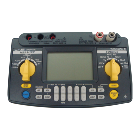
2. Names and Functions of Parts MEASURE SOURCE IM CA71-E... - Page 23 2. Names and Functions of Parts ■ Front Panel 1) POWER Key Turns on/off the power supply. 2) LIGHT Key Turns on/off the backlight of the LCD. MEASURE Mode – Functions for Measurement 3) DC Voltage, AC Voltage, Resistance and Pulse Input Terminals Serve as H (positive) and L (negative) input terminals when you measure DC voltage, AC voltage, resistance, and pulse signals.
- Page 24 2. Names and Functions of Parts 8) MEASURE OFF Key Turns on/off the MEASURE mode. Turning off the mode causes the measured value shown on the LCD to disappear. If the MEASURE mode is not in use and therefore turned off, the power to the measurement circuit within the calibrator is also turned off.
- Page 25 2. Names and Functions of Parts 16) TEMP Key Allows you to monitor temperature by selecting from the room temperature (°C), reference junction temperature (°C), thermocouple (mV) and RTD (Ω) options. 17) n/m Key Turns on/off the divided output function (n/m). Output Setting Keys Set the output value of a source function.
- Page 26 2. Names and Functions of Parts ■ Side and Rear Panels 20) FUSE A holder for housing a fuse that protects the input during DC current measurement. 21) R.J.INPUT A connector to which the external reference junction compensation sensor is connected. 22) AC Adapter Connection Jack 23) Battery Holder Opening the cover reveals the battery holder and DIP switch.
- Page 27 2. Names and Functions of Parts g) MEM NO. indicator Shows a memory number when the memory function is selected. h) AUTO STEP indicator Comes on when the auto step function is selected. Divided output function (n/m) indicator Comes on when the divided output function (n/m) is selected. The most significant two digits “18”...
-
Page 28: Before Starting Source/Measurement
3. Before Starting Source/ Measurement ■ Operating Precautions Precautions for Safe Use of the Instrument ● When using the instrument for the first time, be sure to read the instructions given on pages vi to ix of the section, “Precautions for Safe Use of the Instrument.” ● Do not open the instrument’s case. Opening the case is extremely hazardous, as the instrument contains high-voltage parts. - Page 29 3. Before Starting Source/Measurement ● If you are using an AC adapter with the instrument and will not use the instrument for a prolonged period, disconnect the power cord plug from the wall outlet. ● For handling precautions regarding the batteries, see “Installing or Replacing the Batteries”...
- Page 30 3. Before Starting Source/Measurement NOTE • Use the instrument under the following environmental conditions if precise source or measurement is your requirement: Ambient temperature range: 23±5°C; ambient humidity range: 20 to 80% RH (non-condensing) When using the instrument within a temperature range of 0 to 18°C or 28 to 50°C, add a value based on the temperature coefficient shown in Chapter 12, “Specifications (page 12-1),”...
- Page 31 3. Before Starting Source/Measurement CAUTION • To avoid the risk of fluid leakage or battery explosion, install batteries with their positive and negative electrodes correctly positioned. • Do not short-circuit the batteries. • Do not disassemble or heat the batteries or throw them into fire. •...
- Page 32 3. Before Starting Source/Measurement Step 1: Remove the lead cables and AC adapter and turn off the calibrator before you begin installing batteries. Step 2: Remove the battery holder cover by sliding it in the direction indicated by → OPEN. Step 3: Install four AA-size (LR6) alkaline batteries in the battery holder with their positive and negative electrodes positioned correctly as indicated on the holder.
- Page 33 • To prevent the possibility electrical shock or fire, be sure to use the AC adapter and the power cord supplied by YOKOGAWA. Additionally, do not use the AC adapter and the power cord supplied with this instrument with another instrument.
- Page 34 à la tension de l'alimentation électrique avant la mise sous tension. • Pour éviter tout risque d'électrocution ou d'incendie, veiller à utiliser l'adaptateur secteur et le cordon d'alimentation fournis par YOKOGAWA. De plus, ne pas utiliser l'adaptateur secteur et le cordon d'alimentation fournis avec cet instrument avec un autre instrument.
- Page 35 3. Before Starting Source/Measurement NOTE • Before disconnecting the AC adapter from an AC power source, turn off the calibrator by pressing the key. • When operating the calibrator on batteries, disconnect the AC adapter plug from the instrument. Once you connect the AC adapter plug to the instrument, the instrument no longer operates on batteries.
- Page 36 ■ Operating Environment Operating Environment Ambient Temperature and Humidity Use the CA51/71 in the following environment: • Ambient temperature: 0 to 50°C • Ambient humidity: 20 to 80 % RH (no condensation) • Location: indoors • Operating altitude: 2000 m max. above sea level.
- Page 37 Measurement Category IV. French AVERTISSEMENT L'instrument est conçu pour la catégorie de mesure III. Ne pas utiliser le CA51 ou CA71 pour des mesures dans un endroit qui se situe dans la catégorie de mesure IV. Measurement Description Remarks...
- Page 38 1000V 10A CAT III / 600V 10A CAT IV With no caps: 1000V 10A CAT II Pollution Degree The pollution degree of the CA51 or CA71 in the operating environment is 2. Pollution Degree applies to the degree of adhesion of a solid, liquid, or gas which deteriorates withstand voltage or surface resistivity.
-
Page 39: Source
4. Source From the calibrator, you can source a DC voltage, DC current, SINK current, resistance, thermocouple, RTD, frequency or pulse signal. WARNING • To avoid electrical shock, do not apply any voltage above 30 V to the output terminals. Always use the calibrator in locations with a voltage to ground below 30 V. -
Page 40: Connecting Cables To Terminals
4.1 Connecting Cables to Terminals 4.1 Connecting Cables to Terminals CAUTION Tighten the output terminal knob by hand. Do not use a tool or the like. Tightening the knob using a tool or the like may damage the terminal, resulting in the disability of normal generation. Before storing the instrument in the carrying case, tighten the output terminal knob. - Page 41 4.1 Connecting Cables to Terminals Black Black Lead cables for source (98020) For DC voltage, DC current, thermocouple or pulse output Step 1: Connect the red lead cable for source (P/N: 98020) to the H output terminal and the black lead cable to the L output terminal. Step 2: Connect the two clips of the cables to the input of equipment under test while making sure the polarities are correct.
-
Page 42: Sourcing Dc Voltage, Dc Current Or Sink Current Signal
4.2 Sourcing DC Voltage, DC Current or SINK Current Signal 4.2 Sourcing DC Voltage, DC Current or SINK Current Signal 4.2.1 Sourcing DC Voltage or DC Current Signal Step 1: Using the Function selector switch, select the desired source function from 100mV TC , 1V , 10V , 30V and 20mA . Step 2: The LCD shows the default value and unit of the source function. -
Page 43: Ma Function
4.2 Sourcing DC Voltage, DC Current or SINK Current Signal If either of the following cases applies, the protection circuit works to turn off the output. • The output terminals or the lead cables for source connected to the output terminals are short-circuited or an excessive load current has flowed through the cables when a voltage is being output. -
Page 44: Ma Sink Function
4.2 Sourcing DC Voltage, DC Current or SINK Current Signal 4.2.3 20 mA SINK Function The 20 mA SINK function can draw a preset amount of current from an external voltage source to the H terminal. Thus, you can use the calibrator in a loop test, for example, as a simulator for two-wire transmitters. -
Page 45: Using As 24-V Loop Power Supply
4.2 Sourcing DC Voltage, DC Current or SINK Current Signal 4.2.4 Using As 24-V Loop Power Supply A maximum load current of 22 mA can be drawn from the calibrator by selecting the 30 V range and setting the sourced voltage to 24 V. With this function, you can use the calibrator as a loop power supply in place of the distributor in a two-wire loop, as shown in the following figure. -
Page 46: Sourcing Resistance Or Rtd Signal
4.3 Sourcing Resistance or RTD Signal 4.3 Sourcing Resistance or RTD Signal • The calibrator sources a resistance signal by 1) receiving the resistance-measuring current I supplied from the device being calibrated, such as a resistance meter or RTD thermometer, and 2) delivering the voltage V = R × I proportional to the preset resistance R between the output terminals, and 3) thus producing the equivalent resistance R = V/I. - Page 47 4.3 Sourcing Resistance or RTD Signal ■ Output Method Based on Three-wire Connection Attach another lead cable to the L output terminal, as shown in the following figure. The output is provided through the three wires, H, L and L’. Connect these three wires to the device being calibrated. Three-wire measuring equipment SOURCE CA71...
-
Page 48: Sourcing Thermocouple (Tc) Signals
La prise de mesures telles que la connexion de l'appareil à la terre peut réduire son bruit, ce qui réduit l'effet sur le CA71. (Cette mise en garde s'applique également à la CA51.) Step 1: Insert the RJ sensor into the R.J.INPUT connector of the calibrator. - Page 49 4.4 Sourcing Thermocouple (TC) Signals Step 3: Using the key, select the type of thermocouple. Select the type from K, J, E, T, R, B, S, N, L and U. The selected type of thermocouple is shown on the LCD. Step 4: When the RJ sensor is connected, the calibrator goes into the RJ ON status and the RJON symbol appears on the LCD Step 5: Set the output value digit by digit using each pair of output setting keys.
- Page 50 4.4 Sourcing Thermocouple (TC) Signals The calibrator has a built-in RJ sensor (INT RJ) that compensates for the measured reference junction temperature. You can generate thermoelectromotive force that is based on the measured temperature from the calibrator's output terminal and roughly check the measurement (reading) on the thermometer under verification.
-
Page 51: When No Rj Sensor Is Used
4.4 Sourcing Thermocouple (TC) Signals 4.4.2 When No RJ Sensor Is Used From the output terminals, the calibrator sources a thermoelectromotive force corresponding to the preset temperature of a selected thermocouple. The thermoelectromotive force is sourced with reference to 0°C. Step 1: Using the function selector switch, select 100mV TC . Step 2: Using the key, select the type of thermocouple. -
Page 52: Sourcing Pulse Signals
4.5 Sourcing Pulse Signals 4.5 Sourcing Pulse Signals You can source a preset type of continuous pulse train, a pulse signal with a preset frequency, or the preset number of pulses. Amplitude setpoint Continued Frequency-based signal Source of number of pulses n = Preset number OFF ON of pulses Automatically turned off... - Page 53 4.5 Sourcing Pulse Signals Step 5: Set the output value digit by digit using each pair of output setting keys. Each pair of keys corresponds to each digit of the LCD reading. Each press of the key increases or decreases the digit. Increasing the digit from 9 or decreasing it from 0 causes the digit to overflow or underflow, allowing you to set the output value without interruption.
-
Page 54: Sourcing The Preset Number Of Pulses (Pulse Cycle)
4.5 Sourcing Pulse Signals 4.5.2 Sourcing the Preset Number of Pulses (Pulse Cycle) Step 1: Using the function selector switch, select PULSE . The LCD shows the default frequency Step 2: Using the key, set the frequency range. Each press of the key cycles through the 500.0 Hz, 1000 Hz and 10 kHz options. - Page 55 4.5 Sourcing Pulse Signals Step 6: Press the key once again to show on the LCD. Then, press the key. The source setpoint reading of the LCD changes to a numeric value, which represents the number of pulses. Step 7: Set the number of pulses value digit by digit using each pair output setting keys.
-
Page 56: Using The Contact Output
4.5 Sourcing Pulse Signals 4.5.3 Using the Contact Output You can turn on or off the output terminals. This setting is possible for both the mode of sourcing a continuous pulse train and the mode of sourcing a given number of pulses. An FET is used as the contact switching device. Since the way of using the contact output is the same for both the source of continuous pulse trains and the source of a number of pulses, this subsection only refers to the procedure for... - Page 57 4.5 Sourcing Pulse Signals Step 7: Pressing the key causes the indicator on the LCD to change from The output terminals turn on and off at the preset frequency. Step 8: To turn off the output, press the key once again. appears on the LCD and the output terminals are open-circuited.
-
Page 58: Divided Output Function (N/M)
4.6 Divided Output Function (n/m) 4.6 Divided Output Function (n/m) The divided output function (n/m) outputs a value n/m times the setpoint of a voltage, current, resistance, thermocouple or RTD signal. Thus, the output value is defined as: Output value = Main setpoint × (n/m) Keys and labels related to divided output function (n/m) For details on how to set the sourced signal level of each range, see Sections 4.2, “Sourcing DC Voltage, DC Current or SINK... -
Page 59: Sweep Function
4.7 Sweep Function Step 6: Pressing the key causes the indicator on the LCD to change from The calibrator sources a (main setpoint) × (n/m) signal between the output terminals for each range selected. Step 7: To turn off the output, press the key once again. -
Page 60: Temperature Monitor Function
4.9 Temperature Monitor Function 4.9 Temperature Monitor Function Using the key, you can show the monitored temperature on the LCD, as described below. ■ When the Voltage, Current, Resistance or Pulse (Continuous Pulse Train or Number of Pulses) Range Is Selected The reading of a sourced signal remains changed to the temperature detected by the built-in temperature sensor of the calibrator as long as the key is kept held down. -
Page 61: Measurement
5. Measurement WARNING • In an application where the calibrator is used together with the supplied lead cables for measurement, the maximum allowable voltage from the input terminals to ground is 300 V. To avoid electrical shock, do NOT use the calibrator at any voltage exceeding this maximum. -
Page 62: Connecting Cables To Terminals
5.1 Connecting Cables to Terminals 5.1 Connecting Cables to Terminals ■ For DC voltage, AC voltage, resistance, frequency or pulse signal Step 1: Connect the red lead cable for measurement (P/N: RD031) to the H input terminal and the black lead cable to the L input terminal. Step 2: Connect the two clips of the cables to the measuring terminals of equipment under test while making sure the polarities are correct. - Page 63 5.1 Connecting Cables to Terminals Terminal adapter (99021) WARNING The allowable voltage to ground when the included terminal adapter is attached to the input terminals is 30 Vpeak maximum. Lead cables for measurement (RD031) AVERTISSEMENT La tension admissible à la terre lorsque l'adaptateur de borne inclus est fixé...
- Page 64 5.1 Connecting Cables to Terminals CAUTION • When using the terminal adapter (model: 99021), tighten the knob by hand. Do not use a tool or the like. Tightening the knob using a tool or the like may damage the terminal, resulting in the disability of measurement.
-
Page 65: Measuring 300 V Ac-Range Voltage, Dc Voltage, Ac Voltage Or Dc Current
5.2 Measuring 300 V AC-range Voltage, DC Voltage, AC Voltage or DC Current Terminal adapter (99021) WARNING The allowable voltage to ground when the included terminal adapter is attached to the input terminals is 30 Vpeak maximum. Lead cables for measurement (RD031) AVERTISSEMENT La tension admissible à... -
Page 66: Measuring Dc Or Ac Voltage
5.2 Measuring 300 V AC-range Voltage, DC Voltage, AC Voltage or DC Current 5.2.2 Measuring DC or AC Voltage Step 1: Using the function selector switch, select the measurement function you want to use from Step 2: Using the key, select either DC or AC. The DC or AC symbol appears on the LCD. -
Page 67: Measuring Resistance Or Rtd (Ca71 Only) Signal
5.3 Measuring Resistance or RTD (CA71 only) Signal 5.3 Measuring Resistance or RTD (CA71 only) Signal Step 1: Using the function selector switch, select Ω RTD . Step 2: Using the key, select the range. Pressing the key cycles through the 400 Ω, Pt100 and JPt100 options. •... -
Page 68: Measuring Temperature With
5.4 Measuring Temperature with Thermocouple (TC) - CA71 only - 5.4 Measuring Temperature with Thermocouple (TC) - CA71 only - NOTE Use the terminal adapter in locations where any voltage higher than 30 V will never be imposed on the measuring circuit. Step 1: Using the function selector switch, select 100mV TC . -
Page 69: Measuring Frequency Or Pulses
5.5 Measuring Frequency or Pulses 5.5 Measuring Frequency or Pulses 5.5.1 Operating the Calibrator for Frequency Measurement Step 1: Using the function selector switch, select FREQ 30Vmax . Step 2: Using the key, select 100 Hz, 1000 Hz or 10 kHz. Pressing the key cycles through the 100 Hz, 1000 Hz, 10 kHz, CPM and CPH options. - Page 70 5.5 Measuring Frequency or Pulses NOTE • If you press the key after the completion of counting while the indicator is lit, the calibrator restarts counting from 0. • If you press the key halfway before the selected time (one minute or one hour) expires, the calibrator stops counting at that moment.
-
Page 71: Memory Functions
6. Memory Functions The built-in memory has the following four functions. With a pair of sourced and measured signal values in a set, the calibrator can handle a maximum of 50 sets of data (hereinafter simply referred to as data) by means of its built-in memory. -
Page 72: Saving Data Into Memory
6.1 Saving Data into Memory 6.1 Saving Data into Memory 6.1.1 Saving Data in the Order of Memory Numbers Step 1: Press the key. The MEM No. indicator on the LCD turns on. At this point, the indicator shows a memory number immediately following the one most recently used to save data. Step 2: Pressing the key saves the sourced and measured (currently on-display) signal values at that moment into... - Page 73 6.1 Saving Data into Memory ndicates the memory number with which data is already saved. All these are not yet used. (Case I) 01 02 03 04 05 06 07 08 09 10 11 12 13 14 15 16 49 50 Indication when selected MEM No.07 These are not yet used.
-
Page 74: Saving Data By Selecting Desired Memory Number
6.1 Saving Data into Memory 6.1.2 Saving Data by Selecting Desired Memory Number Step 1: Press the key. The MEM No. indicator on the LCD turns on. Step 2: Using the pair of key, select the desired memory number (address). Step 3: Pressing the key saves the sourced and measured (currently on-display) signal values at that moment into the area with the selected memory number (address). -
Page 75: Reading Data From Memory
6.2 Reading Data from Memory NOTE To stop overwriting the data, press the key one time. This cancels saving data, reverting to the original state of being able to save/read data to/from memory. To cancel the memory mode (saving/reading), press the key one more time. -
Page 76: Clearing Data In Memory
6.3 Clearing Data in Memory 6.3 Clearing Data in Memory 6.3.1 Clearing Data by Selecting Desired Memory Number Step 1: Press the key once. The MEM No. indicator on the LCD turns on. Step 2: Using the pair of key, select the memory number whose data you want to clear. Step 3: Pressing the key causes the LCD to show the alarm indication (no.88 indicates object MEM No. -
Page 77: Clearing All In-Memory Data Globally
6.3 Clearing Data in Memory 6.3.2 Clearing All In-Memory Data Globally Step 1: Press the key once. The MEM No. indicator on the LCD turns on. Step 2: Hold down the key for at least five seconds. The LCD shows the alarm indication. Step 3: Pressing the key once again clears all of the data in memory. -
Page 78: Functions Provided By Dip Switch
7. Functions Provided by DIP Switch By configuring the DIP switch, you can use the functions listed below. The DIP switch can be found by removing the battery holder cover at the back of the calibrator. CAUTION Turn off the calibrator before you change the DIP switch configuration. French ATTENTION Désactiver l’étalonneur avant de modifier la configuration du commutateur DIP. -
Page 79: Sweep Function
7.1 Sweep Function 7.1 Sweep Function The sweep function lets you linearly change the calibrator output as shown in the following figure. The SOURCE ON The SOURCE OFF indication blinks. indication blinks. Setpoint Sourced-value reading Actual output SOURCE ON Press Press key operation (ON) When the SOURCE ON key is... - Page 80 7.1 Sweep Function Step 6: Using the pair of keys, set the upper limit of the signal to be output. The lower limit is set to a value predetermined depending on the selected range. Step 7: Pressing the key initiates sweeping and the output value begins to increase.
-
Page 81: Auto Step Function
7.2 Auto Step Function 7.2 Auto Step Function The auto step function automatically changes the variable n of the n/m output in a step-by-step manner, as shown in the following figure, when the divided output function (n/m) is selected. Sourced-value reading Setpoint Actual output Stepping time setpoint SOURCE ON... - Page 82 7.2 Auto Step Function Step 8: Using each pair of keys, set the value of the denominator m and the starting setpoint of the enumerator n. (See Section 4.6, "Divided Output Function (n/m), for further details.) The starting setpoint is the minimum of the variable n for auto step operation.
-
Page 83: Selecting The Int Rj Function
7.3 Selecting the INT RJ Function 7.3 Selecting the INT RJ Function The INT RJ function compensates for the measured reference junction temperature by using the calibrator's built-in RJ sensor. The function enables you to generate thermoelectromotive force that is based on the measured temperature from the calibrator's output terminal. -
Page 84: Selecting The Ipts-68 Function
7.4 Selecting the IPTS-68 Function 7.4 Selecting the IPTS-68 Function By placing switch 4 (IPTS-68 switch) in the ON (right-side) position, you can select the IPTS-68 temperature scale when you choose the type-K, E, J, T, N, R, S or B thermocouple or the Pt100 RTD. Placing the switch in the OFF position results in the selection of the ITS-90 temperature scale. -
Page 85: Communication Function - Ca71 Only
8. Communication Function - CA71 only - You can configure the calibrator from a personal computer just as you do with the calibrator's panel keys (except for turning on/off the power, configuring the function selector switch, and setting the communication function). You can also verify the setpoint, measured value and status of the calibrator. -
Page 86: Setting The Mode
8.2 Setting the Mode 8.2 Setting the Mode Step 1: Press the key while simultaneously holding down key. The LCD shows in its upper section and either in its lower section. Step 2: Using the pair of keys, select Step 3: Press the key to confirm your mode selection. If you set the mode to , the LCD shows When the... -
Page 87: Data Format
8.4 Data Format When communication is in progress, the indicator blinks, telling you data is being output. Care must be taken therefore, since the hold function of the MEASURE mode is disabled if you select 8.4 Data Format Data is output from the calibrator in the following format. Source: Function Range... -
Page 88: Commands
8.6 Commands 8.6 Commands Command Description Turns the back lighting on and off/queries the current setting. Moves down the “m-th” digit of the sourced setpoint by one digit. Moves up the “m-th” digit of the sourced setpoint by one digit. Enables/Disables the output data header/queries the current setting. -
Page 89: Detailed Description Of Commands
8.7 Detailed Description of Commands 8.7 Detailed Description of Commands Turns the back lighting on and off /queries When normal the current setting. condition Syntax for setting BLm<delimiter> Syntax for query BL?<delimiter> Response: BLm<delimiter> ⇒ Description of parameter m=0: Off m=1: On Moves down the “m-th” digit of the sourced setpoint When normal by one digit. - Page 90 8.7 Detailed Description of Commands When normal Queries the measurement function. condition Syntax for query MF?<delimiter> ⇒ Response: MFm<delimiter> Description of parameter m: Measurement function m=0: 300V AC m=1: 100V m=2: 10V m=3: 1V m=4: 100mV m=5: Resistance m=6: Frequency m=7: Current When normal On/Off of measurement/queries the current setting.
- Page 91 8.7 Detailed Description of Commands When normal Outputs measured value. condition/adjustment Syntax for setting OD<delimiter> ⇒ Response: ODabcde<delimiter> Description of parameter <Header section> (Output only when the header is set to “enabled”.) a= V: Voltage A: Current O: Resistance T: Temperature F: Frequency b= DC: Direct current AC: Alternating current...
- Page 92 8.7 Detailed Description of Commands When normal Sets sourced setpoint/queries the current setting. condition Syntax for setting SDm<delimiter> Syntax for query SD?<delimiter> Response: SDm<delimiter> ⇒ Description of parameter m: Sourced setpoint (7 digits) ex. +1.0000 When normal Queries the source function. condition Syntax for query SF? <delimiter>...
- Page 93 8.7 Detailed Description of Commands When normal Switches between the normal and adjustment condition/adjustment modes/queries the current setting. Syntax for setting SYm<delimiter> Syntax for query SY?<delimiter> Response: SYm<delimiter> ⇒ Description of parameter m: Mode m=0: Normal mode m=1: Adjustment mode Sets the sourced setpoint/queries the current setting.
- Page 94 8.7 Detailed Description of Commands Queries the measurement function. When adjustment Syntax for query CMF?<delimiter> Response: CMFm<delimiter> ⇒ Description of parameter m: Measurement function m=0: AC 300V m=1: 100V m=2: 10V m=3: 1V m=4: 100mV m=5: Resistance m=6: Frequency m=7: Current Queries the source function.
- Page 95 8.7 Detailed Description of Commands Sets divided output (n/m) mode/queries the current When normal setting. condition Syntax for setting MNm<delimiter> Syntax for query MN?<delimiter> Response: MNm<delimiter> ⇒ Description of parameter m: n/m mode m=0: Off m=1: On Sets n/m values in divided output (n/m) mode/ When normal queries the current setting.
-
Page 96: Troubleshooting And Calibration
9. Troubleshooting and Calibration ■ Troubleshooting Failure Checklist Troubleshoot the cause of any problem using the following checklist. Should the problem persist even if you have taken the given corrective action or if you notice any problem not listed herein, contact the vender from which you purchased the instrument. Problem Corrective Action The LCD shows nothing even... - Page 97 9. Troubleshooting and Calibration ■ Calibration We recommend that you calibrate the instrument once a year to maintain its accuracy (high accuracy). For a service of calibration, contact the dealer from which you purchased the instrument. IM CA71-E...
-
Page 98: Method Of Calibrator Adjustment
10. Method of Calibrator Adjustment We recommend that you calibrate the instrument once a year to maintain its accuracy (high accuracy). If the calibrator needs to be readjusted, follow the procedure described below. For a service of calibration or readjustment, contact the dealer from which you purchased the instrument. - Page 99 10.1 Calibration Standard Selection and Environmental Requirements Measurement Functions Function Range Standard's Measuring to Be to Be Accuracy Remarks Name Range Adjusted Adjusted 100 mV 100 mV ±(0.005%+4 μV) ±(0.005%+40 μV) 10 V 10 V ±(0.005%+0.4 mV) High-precision 100 V 100 V ±(0.01%+4 mV) calibrator 20 mA...
-
Page 100: Adjusting Source Functions
See the figure below. *1: Adjust the source functions so that the readings of the calibration standard (output values of the CA51/71) match the adjustment points listed above. • You can also select only the range in need of readjustment to adjust it separately. - Page 101 10.2 Adjusting source Functions Step 3: From Table 10.1, select the range you want to adjust. Then, point the function selector switch to that range and press the key. Step 4: Conform that the symbol is appearing on the LCD. Step 5: Read the calibrator output on the calibration standard. Then, using the lowest-order pair of keys, adjust the reading so that it matches the given CAL 0...
- Page 102 10.2 Adjusting source Functions NOTE • Saving to memory results in the overwriting of existing data. Be extremely careful since the previous adjustment setpoints are cleared. • Both the thermocouple and RTD ranges are adjusted at the same time when the 100 mV and 400 Ω ranges are adjusted. With the CAL mode selected, press the key while holding down key.
- Page 103 10.2 Adjusting source Functions French ATTENTION Précautions lors du réglage de la plage 400 Ω pour la source du signal de résistance (1) Réglage du décalage interne Lors du réglage d'une résistance de 0,00 Ω, s’assurer que la tension entre les bornes H et L est inférieure ou égale à ±20 μV. Si la tension dépasse les limites, des réglages internes doivent être effectués.
-
Page 104: Adjusting Measurement Functions
10.3 Adjusting Measurement Functions 10.3 Adjusting Measurement Functions Table 10.2 Adjustment Setpoints of Measurement Functions Adjustment Points * Range Remarks CAL 0 CAL FS DC 100 mV 100 mV DC 1 V DC 10 V 10 V DC 100 V 100 V DC 20 mA 20 mA DC 100 mA 100 mA 400 Ω... - Page 105 10.3 Adjusting Measurement Functions CAL-mode Operation Keys and Display Indications Step 4: Apply the CAL FS adjustment setpoint input of each range in Table 10.2 from the calibration standard to the H and L input terminals of the calibrator. Step 5: Pressing the key confirms the CAL FS adjustment setpoint.
-
Page 106: Adjusting Ac Voltage And Resistance
10.3 Adjusting Measurement Functions 10.3.2 Adjusting AC Voltage and Resistance (400 Ω) Ranges Step 1: Press the key while simultaneously holding down key. The LCD shows Step 2: Pressing the highest-order key causes the LCD to show Step 3: Pressing the key enters the measurement CAL mode. indicator blinks on the LCD and the symbol appears. -
Page 107: Notes On The Adjustment Of Temperature Ranges
10.4 Notes on the Adjustment of Temperature Ranges - CAL71 only - Step 9: The 0 and FS symbols stop blinking, causing the calibrator to return to the state discussed in step 4. Using the measurement range setting rotary switch, select the next range. By repeating steps 4 to 8, you can adjust the measurement function assigned to that range. -
Page 108: Using Accessories
11. Using Accessories When attaching accessories to the calibrator, refer to the following figure. When connecting the included terminal adapter, make sure the adapter is positioned in the correct orientation. Terminal adapter (99021) WARNING The allowable voltage to ground when the included terminal adapter is attached to the input terminals is Black Black 30 Vpeak maximum. -
Page 109: Specifications
12. Specifications (1) Signal sourcing unit range and accuracy (for both CA51 and CA71) ±(% of setting + μV, mV, mA, Ω or °C) Accuracy Parameter Reference Range Remarks Resolution (23±5°C per year) 100 mV - 10.00 –110.00 mV ±(0.02% + 15 μV) 10 μV... - Page 110 12. Specifications (2) Measurement unit range and accuracy (for both CA51 and CA71) Accuracy: ±(% of reading + µV, mV, µA, Ω or dgt (digit)) Accuracy Remarks Resolution Parameter Reference Range (23±5°C per year) ±(0.025% + 20 µV) 10 µV 100 mV 0 –...
- Page 111 12. Specifications ■ General Specifications Signal sourcing unit Approx. 1 second response time: (time between start of voltage change and when voltage enters accuracy range) Signal sourcing unit Approx. 32 V voltage limiter: Signal sourcing unit Approx. 25 mA current limiter: Divided output (n/m) function: Output = setting ×...
- Page 112 12. Specifications Operating temperatur and humidity 0 to 50°C, 20 to 80% RH (no condensation) ranges: Storage temperature and humidity -20 to 50°C, 90% RH or less (no condensation) ranges: External dimensions: Approx. 190 (W) × 120 (H) × 55 (D) mm Weight: Approx.
- Page 113 EU RoHS Directive compliant For conformity to environmental regulations and/or standards other than EU, contact your nearest YOKOGAWA office (PIM113-01Z2). If you obtained this manual separately from the product, the specifications in this manual may differ from those of the product.
- Page 114 12. Specifications ■ External Dimensions Unit: mm 54.5 Note: This figure shows the CA71, but there is no difference in exterior from the CA51. 12-6 IM CA71-E...
-
Page 115: 13. Regulations And Sales In Various Countries And Regions
This marking indicates that you must not discard this electrical/ electronic product in domestic household waste. When disposing of products in the EEA or UK, contact your local Yokogawa office in the EEA or UK respectively. (*EEA: European Economic Area) 13.2 Batteries and Waste Batteries... -
Page 116: Authorized Representative In The Eea
Yokogawa Europe B.V. is the Authorized Representative of Yokogawa Test & Measurement Corporation for this Product in the EEA. To contact Yokogawa Europe B.V., see the separate list of worldwide contacts, PIM 113-01Z2. 13.4 Disposal When disposing of this instrument, follow the laws and ordinances of the country or region where the product will be disposed of. -
Page 117: For The Pollution Control Of Electronic And Electrical Products Of The People's Republic Of China
13.5 For the Pollution Control of Electronic and Electrical Products of the People's Republic of China 13.5 For the Pollution Control of Electronic and Electrical Products of the People's Republic of China This manual is valid only in China. 产品中有害物质的名称及含量 有害物质 部件名称 铅 汞 镉 六价铬 多溴联苯 多溴二苯醚 (Pb) (Hg) (Cd) (Cr(VI)) (PBB)... -
Page 118: Appendix 1 Reference Junction Compensation
Appendix 1 Reference Junction Compensation Standard thermocouple tables give 0°C as the temperature of the reference junction. Normally, the input terminal part (reference junction) of a thermometer (device under calibration) is at room temperature. (This results in an error equivalent to the difference between 0°C and room temperature.) Reference junction compensation means measuring (detecting) the temperature of the reference junction, calculating the temperature difference (difference of thermoelectromotive force) from 0°C,... - Page 119 A cold junction compensator can be used when, for example, it is not possible to use an RJ sensor. The use of a cold junction compensator enables the reference junction to be 0°C. Cold junction compensator: Yokogawa T-MJ or the equivalent Device under calibration (thermometer)
Need help?
Do you have a question about the CA51 and is the answer not in the manual?
Questions and answers