
Related Manuals for YOKOGAWA CA310


Summary of Contents for YOKOGAWA CA310
- Page 1 User’s CA310 Volt mA Calibrator Manual CA320 TC Calibrator CA330 RTD Calibrator Getting Started Guide IM CA310-02EN 3rd Edition...
- Page 2 Thank you for purchasing the CA310 Volt mA Calibrator, CA320 TC Calibrator, or CA330 RTD Calibrator. This operation guide focuses on the handling precautions, basic operations, and specifications of the CA310/CA320/CA330. To ensure correct use, please read this manual thoroughly before beginning operation. Keep this manual in a safe place for quick reference in the event that a question arises.
- Page 3 • Every effort has been made in the preparation of this manual to ensure the accuracy of its contents. However, should you have any questions or find any errors, please contact your nearest YOKOGAWA dealer. • Copying or reproducing all or any part of the contents of this manual without the permission of YOKOGAWA is strictly prohibited. Trademarks •...
-
Page 4: Product Registration
Product Registration Thank you for purchasing YOKOGAWA products. YOKOGAWA provides registered users with a variety of information and services. Please allow us to serve you best by completing the product registration form accessible from our homepage. http://tmi.yokogawa.com/ IM CA310-02EN... -
Page 5: Checking The Contents Of The Package
Unpack the box and check the contents before operating the instrument. If the wrong items have been delivered, if items are missing, or if there is a problem with the appearance of the items, contact your nearest YOKOGAWA dealer. CA310/CA320/CA330 Check that the product that you received is what you ordered by referring to the model name on the name plate on the rear panel of the main unit. - Page 6 Item Notes Component Number CA310 CA320 CA330 Lead cable 98064 — — For the CA310 1 red, 1 black Lead cable 98040 — — For the CA320 1 red, 1 black Lead cable 98035 — — For the CA330 3 red, 1 black...
- Page 7 Accessory case B9108XA Optional accesories(sold separately) are not covered by warranty of this instrument. When rubber boots are attached, the CA310/CA320/CA330 cannot be stored in the portable case. Cannot be used simultaneously with the included binding post (99045/99046). IM CA310-02EN...
-
Page 8: Safety Precautions
The general safety precautions described herein must be observed during all phases of operation. If the product is used in a manner not specified in this guide, the protection provided by the product may be impaired. YOKOGAWA assumes no liability for the customer’s failure to comply with these requirements. - Page 9 • The maximum voltage application between all I/O terminals and earth is 50 VDC (measurement terminal of CA310) or 42 VDC (other than the measurement terminal of CA310). Do not apply voltages that exceed 50 VDC or 42 VDC .
- Page 10 Ne pas utiliser l’instrument en présence de gaz ou de vapeurs inflammables. Cela pourrait être extrêmement dangereux. Ne pas retirer le capot, ni démonter ou modifier l’instrument Seul le personnel YOKOGAWA qualifié est habilité à retirer le capot et à démonter ou modifier l’instrument. IM CA310-02EN...
- Page 11 • Veillez à utiliser tous les câbles fournis. • La tension maximum autorisée entre toutes les bornes I/O et la terre est de 50 V c.c. (borne mesure du CA310) ou de 42 V c.c. (autre que la borne de mesure du CA310). N’appliquez pas de tension supérieure à 50 V c.c (CA310) ou à...
-
Page 12: Conventions Used In This Guide
Attire l’attention sur des gestes ou des conditions susceptibles de provoquer des blessures légères ou d’endommager l’instrument ou les données de l’utilisateur, et sur les précautions de sécurité susceptibles de prévenir de tels accidents. Note Calls attention to information that is important for the proper operation of the instrument. IM CA310-02EN... -
Page 13: Waste Electrical And Electronic Equipment (Weee), Directive
26. Authorized Representative in the EEA Yokogawa Europe B.V. is the authorized representative of Yokogawa Test & Measurement Corporation for this product in the EEA. To contact Yokogawa Europe B.V., see the separate list of worldwide contacts, PIM 113-01Z2. -
Page 14: Table Of Contents
Authorized Representative in the EEA ........12 Disposing of the Instrument ..........33 Names and Functions of Parts ......14 Specifications ............34 Front Panel, Side Panel, and Rear Panel ......14 CA310 ...................34 Keys ..................15 CA320 ...................36 Display ..................17 CA330 ...................46 Common Specifications ............49 Making Preparations for Measurements ....18... -
Page 15: Names And Functions Of Parts
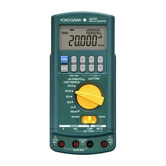
Keys RJ sensor connector Rotary switch (CA320 only) Selects the range and Connect an RJ sensor type. You can sensor. also select the setup mode (SETTING). Measurement/ CA320 source switch TYPE1 TYPE2 I/O terminals CA310 example IM CA310-02EN... -
Page 16: Keys
(CA320)). OUTPUT ON/OFF key Turns the output on and off Starts or Set the output to 0% in span check. stops sweeping in sweep mode. TYPE key Select the sensor. Stops or resumes sweeping in sweep mode. IM CA310-02EN... - Page 17 Turns LOOP POWER on and off if (voltage corresponding to temperature, span % LOOP POWER is in use. display, RJ sensor temperature (CA320)). On the CA330, select the wiring system from 2W (two-wire), 3W (three-sire), and 4W (four-wire). TYPE key Select the sensor. IM CA310-02EN...
-
Page 18: Display
15 Appears when the temperature standard is set to IPTS-68 16 Sensor selection status based on the TYPE key 17 Wiring system. Two-wire: 2W, three-wire: 3W, four-wire: 4W * Appears only for LOOP POWER even when it is set to ON. IM CA310-02EN... -
Page 19: Making Preparations For Measurements
Unplug If Abnormal Behavior Occurs If you notice smoke or unusual odors coming from the instrument, immediately turn off the power, remove the batteries if possible, and contact your nearest YOKOGAWA dealer. General Handling Precautions Do Not Place Objects on Top of the Instrument Never place objects such as other instruments or objects that contain water on top of the instrument. - Page 20 • In an environment with excessive amounts of soot, steam, dust, or corrosive gas • In an environment subject to large levels of mechanical vibration • On an unstable surface • Where an excessive amount of soot, dust, salt, or iron is present IM CA310-02EN...
-
Page 21: Installing The Instrument
• N’utilisez pas cet équipement pour mesurer des points tombant sous les catégories de mesure II, III et IV. ATTENTION Cet équipement est doté de fonctions de mesure et de source de courant et de tension. N’utilisez pas l’équipement lorsqu’il est mouillé. Le cas échéant, un endommagement de l’équipement risquerait de se produire. IM CA310-02EN... - Page 22 • Near noise sources, such as high-voltage equipment or power lines • In an environment subject to large levels of mechanical vibration • On an unstable surface • In an environment where ignition or explosion may occur, such as in explosive gas IM CA310-02EN...
- Page 23 Overlap the case cover over the bottom of the case, and fasten the hook on the strap end and hooks on the sides of the case cover. Antiskid rubber Affix the included antiskid rubber to the location indicated in the following figure. Antiskid rubber (included) IM CA310-02EN...
-
Page 24: Connecting Cables
Making Preparations for Measurements Connecting Cables To connect the CA310, use the included lead cable. CA310 (measurement) 500 mV, 5 V, 30 V, or 50 V range 20 mA or 50 mA range LOOP POWER – Two-wire transmitter DC voltage source... - Page 25 (Lo) CA330 (source) (Hi) (Lo) Example of using a binding post Short bar Short bar Attach according to the terminal color. Resistance measurement terminal of temperature transmitter, temperature converter, etc. SEMSE INPUT INPUT SEMSE (Hi) (Hi) (Lo) (Lo) IM CA310-02EN...
-
Page 26: Using Thermocouple Mini Plugs (Ca320 Only)
To connect the plug and the item to be calibrated, use the same type of thermocouple or compensating lead wire as that used on the item to be calibrated. (Prepare your own thermocouple or compensating lead wires.) When terminal A is in use, reference junction compensation based on the internal temperature sensor is applied. IM CA310-02EN... -
Page 27: Installing And Removing Batteries
Push the battery cover on the rear panel in the direction of the arrow, and open the cover. Remove the old batteries, and insert new batteries with the correct polarities. Attach the battery cover. Close the cover completely until you hear a click. IM CA310-02EN... -
Page 28: Connecting The Ac Adapter
• Pour des détails sur l’utilisation de l’adaptateur c.a., consultez le mode d’emploi de l’adaptateur c.a. Turn the power off. Connect the AC adapter’s DC cable to the AC adapter jack on the instrument’s side panel. Connect the AC adapter to an AC power supply. IM CA310-02EN... -
Page 29: Turning The Power On And Off
• Batteries of different types or different brands are being used together. If the instrument still does not work properly, contact your nearest YOKOGAWA dealer for repairs. Turning the Power Off 1. Hold down the POWER key until OFF appears. -
Page 30: Common Operations
• On the CA320 or CA330, if you select SOURCE, the display shows ON, and output starts. • On the CA310, if you select SOURCE, use the OUTPUT ON/OFF key to turn the output on. The display shows ON, and voltage or current is output. - Page 31 ±25% steps of span Pauses or resumes sweeping On the CA310, press the OUTPUT ON/OFF key to start or stop sweeping. On the CA320/CA330, press the TYPE key to do the same. When sweeping is stopped or paused, you can press the left-most key to set the output span to 0%.
- Page 32 ON/OFF Temperature reference ITS-90 /IPTS-68 — — Extended sensor /G/PL2 — — CA320 to confirm TYPE CA330 Initializes the span setting — Initializes the settings — *: Default value IM CA310-02EN...
-
Page 33: Troubleshooting, Maintenance, And Inspection
Faults and Corrective Actions If servicing is necessary, or if the instrument does not operate properly even after you have attempted to deal with the problem according to the instructions in this section, contact your nearest YOKOGAWA dealer. Reference Problems and Solutions Page The power does not turn on. -
Page 34: Recommended Replacement Parts, Consumable Parts, And Calibration
CA310, CA320, or CA330. If the error appears every time at power-on, repair is necessary. “Err61” and “Err63” appear at There is an error in the calibration data stored in the CA310, CA320, or power-on. CA330. -
Page 35: Specifications
NMRR Approx. 60 dB (50/60 Hz) Measurement terminal maximum input Voltage terminals 50 VDC Current terminals 50 mADC Current terminal input protection PTC protection Measurement display update rate Approx. 1 s Measurement terminal voltage to ground 50 Vpeak IM CA310-02EN... - Page 36 Sweep function Step (25%)/linear Step time 15 s, 30 s, 45 s, 60 s Maximum load C≤0.1 μF, L≤10 mH Output resistance 10 mΩ or less Output response 300 ms or less Source terminal voltage to ground 42 Vpeak IM CA310-02EN...
-
Page 37: Ca320
DIN 43710 0.0°C ≤ t≤ +900.0°C -200.0°C ≤ t < 0.0°C 0.5+|t| x 0.2% 0.5+|t| x 0.2% DIN 43710 0.0°C ≤ t≤ +600.0°C -20.0°C ≤ t < 0.0°C IEC60584-1 0.0°C ≤ t < +100.0°C +100.0°C ≤ t ≤ +1767.0°C IM CA310-02EN... - Page 38 At an ambient temperature (Ta) of 23±5°C, using the internal reference junction compensation function. For the accuracies of other ambient temperatures (Ta<18°C, Ta>28°C), add the temperature coefficient 0.05°C/°C. Source/measured value display resolution: 0.1°C The temperature of the thermocouple plug is balanced with the ambient temperature. IM CA310-02EN...
- Page 39 1.6+|t-100| x 0.5% 1.6+|t-100| x 0.5% +100.0°C ≤ t ≤ +1767.0°C -20.0°C ≤ t < 0.0°C 1.6+|t-100| x 0.5% 1.6+|t-100| x 0.5% IEC60584-1 0.0°C ≤ t < +100.0°C 1.6+|t-100| x 0.5% 1.6+|t-100| x 0.5% +100.0°C ≤ t ≤ +1768.0°C IM CA310-02EN...
- Page 40 At an ambient temperature (Ta) of 23±5°C, using the internal reference junction compensation function. For the accuracies of other ambient temperatures (Ta<18°C, Ta>28°C), add the temperature coefficient 0.05°C/°C. Source/measured value display resolution: 0.1°C The temperature of the terminals or binding post is balanced with the ambient temperature. IM CA310-02EN...
- Page 41 1.4+|t-100| x 0.5% 1.4+|t-100| x 0.5% +100.0°C ≤ t ≤ +1767.0°C -20.0°C ≤ t < 0.0°C 1.4+|t-100| x 0.5% 1.4+|t-100| x 0.5% IEC60584-1 0.0°C ≤ t < +100.0°C 1.4+|t-100| x 0.5% 1.4+|t-100| x 0.5% +100.0°C ≤ t ≤ +1768.0°C IM CA310-02EN...
- Page 42 For the accuracies of other ambient temperatures (Ta<18°C, Ta>28°C), add the temperature coefficient 0.05°C/°C. Source/measured value display resolution: 0.1°C Measured current: 1 mA or less (voltage application, current measurement) The temperature of the reference junction or sensor is balanced with the ambient temperature. IM CA310-02EN...
- Page 43 Specifications External RJ Sensor 90080 (sold separately) Specifications Sensor used: RTD Pt100 (four-wire system) Standalone accuracy: JIS AA class or equivalent Specified current: 1 mA Operating temperature range: –10°C to 55°C Y terminal: M3 screw compatible IM CA310-02EN...
- Page 44 DIN 43710 0.0°C ≤ t ≤ +600.0°C -20.0°C ≤ t < 0.0°C IEC60584-1 0.0°C ≤ t < +100.0°C +100.0°C ≤ t ≤ +1767.0°C -20.0°C ≤ t < 0.0°C IEC60584-1 0.0°C ≤ t < +100.0°C +100.0°C ≤ t ≤ +1768.0°C IM CA310-02EN...
- Page 45 +1000.0°C ≤ t < +1395.0°C These do not include thermocouple errors. At an ambient temperature (Ta) of 23±5°C, without using the internal reference junction compensation function. For the accuracies of other ambient temperatures (Ta<18°C, Ta>28°C), add the temperature coefficient 0.05°C/°C. IM CA310-02EN...
- Page 46 Thermocouple Accuracy Equation Accuracy with respect to the measurement or source temperature (t) is expressed as constant or a linear equation of t. Example: Accuracy for Thermocouple K (terminal A) measurement value of 1000.0°C = ±(0.5 + (1000.0-500)×0.02%)°C = ±0.6°C IM CA310-02EN...
-
Page 47: Ca330
0.0°C ≤ t ≤ +630.0°C 0.2+t x 0.033% 0.2+t x 0.033% Cu10 -100.0°C ≤ t < +260.0°C 0.1 to 3 mA Minco Application Aid #18 Ni120 -80.0°C ≤ t < +260.0°C 0.1 to 3 mA Minco Application Aid #18 IM CA310-02EN... - Page 48 How to View the RTD Accuracy Accuracy with respect to the measurement or source temperature (t) is expressed as constant or a linear equation of t. Example: Accuracy for PT100 measurement value of 100.0°C = ±(0.3 + 100.0x0.033%)°C = ±0.333°C IM CA310-02EN...
- Page 49 5 ms or less (3000 Ω range, excluding PT500 and PT1000) Overcurrent input warning: When the upper limit of excitation current is exceeded Maximum load: C≤0.1 μF, L≤10 mH Sweep: Step (25%)/linear Step time: 15s/30s/45s/60s Maximum input across terminals: 42 Vpeak Maximum input to ground: 42 Vpeak IM CA310-02EN...
-
Page 50: Common Specifications
Display method Segment LCD with backlight function Maximum voltage application Between each terminal and earth 50 VDC or less (CA310) Between each terminal and earth 42 VDC or less (CA320, CA330) External dimensions Approx. 90 (W) × 192 (H) × 42 (D) mm (excluding protrusions) Weight Approx. - Page 51 Pollution degree refers to the degree of adhesion of a solid, liquid, or gas which deteriorates withstand voltage or surface resistivity. Pollution degree 2 applies to normal indoor atmospheres (with only non-conductive pollution). IM CA310-02EN...
-
Page 52: External Dimensions
Specifications External Dimensions CA310 CA320 CA330 Unit: mm Unless otherwise specified, tolerances are ±3% (however, tolerances are ±0.3 mm when below 10 mm). IM CA310-02EN...
Need help?
Do you have a question about the CA310 and is the answer not in the manual?
Questions and answers