Table of Contents
Advertisement
Advertisement
Table of Contents

Subscribe to Our Youtube Channel
Related Manuals for YOKOGAWA DL 1540


Summary of Contents for YOKOGAWA DL 1540
- Page 1 Digital Oscilloscope IM 701510-01E Yokogawa Electric Corporation 7th Edition...
- Page 2 However, should you have any questions or find any errors, please contact your nearest YOKOGAWA representative as listed on the back cover of this manual. • Copying or reproduction of all or any part of the contents of this manual without YOKOGAWA’s permission is strictly prohibited.
- Page 3 Checking the Contents of the Package Unpack the box and check the contents before operating the instrument. If the wrong instrument or accessories have been delivered, if some accessories are missing or if they appear abnormal, contact the dealer from which you purchased them. Main Body Check that the model name and suffix code given on the name plate of the rear panel match those on your order.
-
Page 4: Standard Accessories
Checking the Contents of the Package Standard Accessories The following standard accessories are supplied with the instrument. Make sure that all items are present and undamaged. Power cord (one of the following power cords is supplied according to the instrument's suffix codes) UL/CSA standard VDE standard BS standard... -
Page 5: Optional Accessories
Checking the Contents of the Package Optional Accessories The following optional accessories are available. On receiving these optional accessories, make sure that all the items that you ordered have been supplied and that they are undamaged. If you have any questions regarding optional accessories, or if you wish to place an order, contact the dealer from whom you purchased the instrument. -
Page 6: Safety Precautions
If this instrument is used in a manner not specified in this manual, the protection provided by this instrument may be impaired. Also, YOKOGAWA Electric Corporation assumes no liability for the customer’s failure to comply with these requirements. - Page 7 To prevent an electric shock or fire, be sure to use the power supply cord supplied by YOKOGAWA. The main power plug must be plugged in an outlet with protective grounding terminal. Do not invalidate protection by using an extension cord without protective grounding.
-
Page 8: How To Use This Manual
How to Use this Manual Structure of the Manual This User’s Manual consists of 16 chapters, an Appendix and an Index as described below. Chapter Title Description Functions Describes measurement principles and functions. Although this section does not give a description of the operating methods, it will help you to understand the basic operations. -
Page 9: Conventions Used In This Manual
Conventions Used in this Manual Unit k ..... Denotes “1000”. Example: 100kS/s K ..... Denotes “1024” or “1002”. • Example of when K indicates “1024” : 640 KB (storage capacity of a floppy disk) • Example of when K indicates “1002” : 100 KW (record length for acquisition memory) Used Characters Alphanumerics enclosed in double quotation marks usually refer to characters and set values... -
Page 10: Table Of Contents
Contents Introduction ................................Checking the Contents of the Package ..................Safety Precautions ............................How to Use this Manual ..........................Conventions Used in this Manual ...................... Chapter 1 Functions System Configuration and Block Diagram ................Setting the Vertical and Horizontal Axes ...................................... - Page 11 Contents Chapter 4 Common Operations Starting and Stopping Acquisition ..................... Displaying Waveforms using the Auto Set-up Function ............Initializing Settings ........................Halting a Waveform and Erasing the Halted Waveform (Snap Shot and Clear Trace) ....Performing Calibration ......................Setting Values ..........................Entering Characters using the Keyboard ..................
- Page 12 Contents Chapter 8 Analyzing Waveforms Measuring a V-T Waveform using Cursors ................Measuring an X-Y Waveform using Cursors ................Measuring Waveform Parameters Automatically ..............Using the Linear Scaling Function ..................... 8-14 Performing Waveform Math (Addition, Subtraction and Multiplication) ......... 8-16 Displaying the Power Spectrum (Performing FFT Computation) ..........
- Page 13 Contents Chapter 14 Other Operations 14.1 Using a Trigger Output Signal (for DL1540/DL1540L) ............14-1 14.2 Downloading Waveform Data to an AG Arbitrary Waveform Generator ........14-2 14.3 Checking the System Condition ....................14-3 14.4 Adjusting the Printer Density ..................... 14-4 Chapter 15 Troubleshooting, Maintenance and Inspection 15.1 Troubleshooting .........................
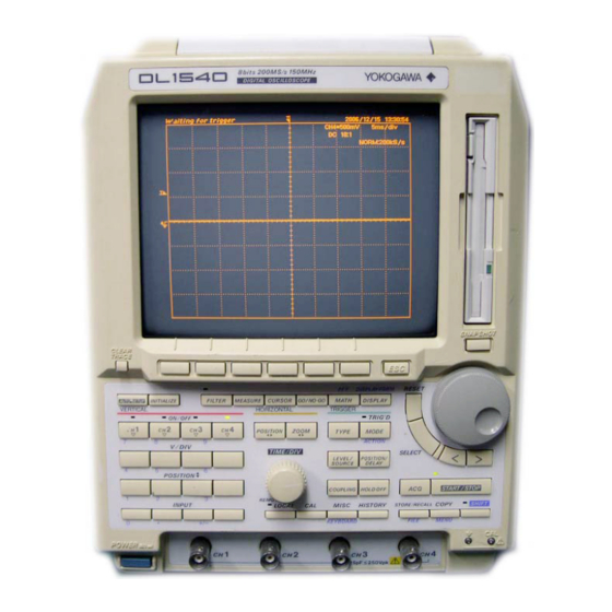
- Page 14 Front Panel / Rear Panel / Top View Front Panel (2 channels are provided with DL1520/DL1520L.) Time axis setting knob →Page 5-10 Floppy disk drive Saving and loading of data from the floppy disk CRT screen →Chapter 12 Description of display contents →Page 2-5 Rotary knob Used to enter setting values and selections...
-
Page 15: Operation Keys / Rotary Knob
Operation Keys / Rotary Knob Operation keys provided with DL1540/DL1540L are shown below. For DL1520/DL1520L, keys relating to CH3 and CH4 and HISTORY key are not provided. Keys and Rotary Knob used for Various Functions CLEAR TRACE key (Page 4-5) ESC key Deletes the currently displayed menu. - Page 16 2.2 Operation Keys / Rotary Knob Keys and Rotary Knob used for Making Trigger Settings TRIG’D indicator Lights up when a trigger is activated. MODE key (Page 6-12) Displays the trigger mode selection menu. SHIFT+MODE(ACTION) key (Page 6-14) TYPE key Displays the action-on-trigger selection menu.
- Page 17 2.2 Operation Keys / Rotary Knob Keys and Rotary Knob used for Analysis of Waveforms MEASURE key (Page 8-6) Displays the setting menu for automated measurement of waveform parameters. CURSOR key (Pages 8-1, 8-5 and 8-19) Displays the setting menu for cursor measurement. RESET key Resets the settings made using the SNAP SHOT...
-
Page 18: Display
Display An example of screen displayed on DL1540/DL1540L is shown below. For DL1520/ DL1520L, waveforms and data relating to CH3 and CH4 are not displayed. Normal Waveform Display Information concerning waveforms →Page 7-15 CH2 . . . Signal waveform of channel 2 20V . - Page 19 2.3 Display Expanded Display → → → → → Refer to page 7-4. Expansion (zoom) box Pre-zoom waveform Time axis setting of the expanded waveform Expanded waveform Expansion rate Expansion setting menu Recalled Waveform → → → → → Refer to page 11-1. Channel No.
-
Page 20: Precautions During Use
Unusual occurrences If you notice smoke or unusual odors coming from the instrument, turn OFF the power and unplug the power cord immediately. Contact your dealer or the nearest YOKOGAWA representative as listed on the back cover of this manual. - Page 21 Installing the Main Unit Installation Position Place the instrument in a flat, horizontal position as shown in the figure below. To tilt the screen slightly forwards, use the support, as shown below also. When using the support, pull it forwards until it is at right angles to the bottom of the instrument, and lock it.
-
Page 22: Connecting The Scsi Cable (For Dl1520L With Suffix Code -C4)
Connecting the SCSI cable (for DL1520L with suffix code -C4) Name, position and pin cofigurationo of the SCSI cable connector • Name : OPTION • Position : Real panel of DL1520L • Pin configuration Pin No. Signal name Pin No. Signal name Pin No. - Page 23 Connecting the SCSI cable (for DL1520L with suffix code -C4) Connecting the SCSI cable CAUTION • When connecting or disconnecting the SCSI cable, turn the power switches OFF on all equipment. Not doing so may cause malfunction, or damage the equipment.
-
Page 24: Connecting The Power Cord
Connecting the Power Cord Before Connecting the Power Make sure that you perform the following steps before connecting the power. Failure to do so may cause electric shock or damage to the instrument. WARNING • Connect the power cord after confirming that the voltage of the power supply complies to the rated electric power voltage for this instrument. - Page 25 For details, refer to Section 4.3 “Initializing Settings” (page 4-4). If there is still no power even after the above points have been checked, contact your nearest YOKOGAWA representative as listed on the back cover of this manual.
-
Page 26: Connecting A Probe
Connecting a Probe Input Terminals A probe (or an input cable such as a BNC cable) must be connected to one of the input terminals (CH1 to CH4, CH1 and CH2 for DL1520/DL1520L) located on the lower section of the front panel. The input impedance is 1 MΩ... - Page 27 Compensating the Probe (Phase Correction) CAUTION Never apply an external voltage to the CAL terminal, as damage to the instrument may result. Operating Procedure 1. Turn ON the power switch. 2. Connect the probe to the input terminal to which the signal is to be applied. 3.
-
Page 28: Setting The Date And Time
Setting the Date and Time Keys and Procedure 1. Press the MISC key to display the MISC menu. Rotary knob 2. Press the “Date/Time” soft key to display the DATE/TIME setting SELECT key menu. ESC key Soft keys Turning the Date/Time ON/OFF 3. -
Page 29: Starting And Stopping Acquisition
Starting and Stopping Acquisition Keys and Procedure 1. Press the START/STOP key to start/stop waveform acquisitioning. 2. In case the indicator located at the upper left of the START/STOP key is lit, waveform acquisition is in progress. 3. In case the indicator located at the upper left of the START/STOP key is not lit, waveform acquisition is not in progress. -
Page 30: Displaying Waveforms Using The Auto Set-Up Function
Displaying Waveforms using the Auto Set-up Function Keys and Procedure 1. Press the AUTO-SETUP key to display the auto set-up execution menu. AUTO-SETUP key Executing auto set-up 2. Press the “AUTOSET EXEC” soft key to perform auto set-up. Soft keys Channels will be turned ON/OFF automatically depending on whether input is applied or not. - Page 31 4.2 Displaying Waveforms using the Auto Set-up Function Auto set-up settings related to the horizontal axis TIME/DIV Set to a value so that between two and four periods of the slowest input signal can be observed. If this is not possible for any of the channel input signals, set to 1ms/ div.
-
Page 32: Initializing Settings
Initializing Settings Keys and Procedure 1. Press the INITIALIZE key to display the initialization execution menu. INITIALIZE key 2. Press the “INITIAL EXEC” soft key to execute initialization. Soft keys Explanation Default settings related to the vertical and horizontal axes CH1 to CH4 All channels ON (CH1/CH2 for DL1520/DL1520L) V/DIV... -
Page 33: Halting A Waveform And Erasing The Halted Waveform (Snap Shot And Clear Trace)
Halting a Waveform and Erasing the Halted Waveform (Snap Shot and Clear Trace) Keys and Procedure 1. Press the SNAP SHOT key to halt the waveform. SNAP SHOT key 2. Press the CLEAR TRACE key to erase the halting waveform. CLEAR TRACE key Explanation Snap Shot Function... -
Page 34: Performing Calibration
Performing Calibration Keys and Procedure 1. Press the CAL key to display the calibration execution menu. Executing manual calibration 2. Press the “EXEC” soft key to execute calibration. Turning automatic calibration ON Soft keys 3. Press the “Auto CAL” soft key to select “ON”. CAL key Explanation About the calibration function... -
Page 35: Setting Values
Setting Values Keys and Procedure Rotary knob Entry using the keyboard SELECT key 1. Press the SHIFT + MISC(KEYBOARD) key to display the ESC key keyboard. Setting by rotary knob and SELECT key 2. Use the rotary knob to select the desired value and press the SELECT key. -
Page 36: Entering Characters Using The Keyboard
Entering Characters using the Keyboard Keys and Procedure 1. Display the keyboard used for entering a file name or comment Rotary knob SELECT key (displayed when your are prompted a character input). 2. Use the rotary knob to select the desired character or symbol and press ESC key the SELECT key. -
Page 37: Turning Display Of Input Signal Waveforms On/Off
Turning Display of Input Signal Waveforms ON/ Keys and Procedure 1. The waveform will appear on the display after you have pressed the CH key CH key. The indicator above the CH key will light up. 2. If you want to display all waveforms, press all the CH keys, and verify that all the indicators light up. -
Page 38: Setting The Input Coupling
Setting the Input Coupling Keys and Procedure 1. Press the INPUT key corresponding to the channel for which input Rotary knob coupling is to be selected. The input setting menu will be displayed. 2. Press the soft key corresponding to the desired coupling type. 3. - Page 39 5.2 Setting the Input Coupling Offset voltage and displayed value (measured value) The offset function eliminates unnecessary DC voltage from an input signal voltage. If the offset voltage is set to a positive value, the input signal is displayed with the offset voltage subtracted from it, as shown below.
-
Page 40: Setting The Probe Attenuation
Setting the Probe Attenuation Keys and Procedure 1. Press the INPUT key corresponding to the channel for which the probe attenuation is to be selected. The input setting menu will be displayed. 2. Press the “Probe” soft key to display the probe selection menu. Soft keys 3. -
Page 41: Inverting A Waveform
Inverting a Waveform Keys and Procedure 1. Press the INPUT key corresponding to the channel whose waveform is to be inverted. The input setting menu will be displayed. 2. Press the “Invert” soft key to select “ON”. Soft keys INPUT key Explanation Relevant channels The input signals for channels CH1 to CH4 (for DL1520/DL1520L, CH1/CH2) can be... -
Page 42: Setting The Vertical Sensitivity
Setting the Vertical Sensitivity Keys and Procedure 1. Press the V/DIV key of the desired channel to display the vertical Rotary knob sensitivity setting menu. Verify that the “CAL” setting is highlighted. 2. Turn the rotary knob to set the desired sensitivity (V/div). soft keys 3. -
Page 43: Changing The Waveform's Vertical Position
Changing the Waveform’s Vertical Position Keys and Procedure 1. Press the POSITION key of the channel whose waveform you want Rotary knob to move. 2. Select the position of the screen where you want the waveform to be displayed by pressing the corresponding soft key. Soft keys 3. -
Page 44: Selecting The Timebase
Selecting the Timebase Keys and Procedure 1. Press the MISC key to display the MISC menu. Rotary knob 2. Press the “Time Base...” soft key to display the timebase setting menu. Soft keys 3. Select the required timebase by pressing the corresponding soft key. “EXT CH4”... - Page 45 5.7 Selecting the Timebase If a clock signal exceeding the maximum input voltage is input to the each CAUTION terminal, damage to the internal circuits of the instrument may result. When “EXT CH4” is selected (available on DL1540/DL1540L) Input a clock signal to the CH4 input terminal on the front panel. The clock signal must conform to the specifications given below.
-
Page 46: Setting The Time Axis
Setting the Time Axis Keys and Procedure Turn the time axis setting knob to adjust the time axis setting. The time axis setting value, displayed in the lower right corner of the screen, will change accordingly. Time axis setting knob Explanation Time axis setting range T/div can be set within the range of 5 ns/div to 50 s/div (in multiples of 1, 2 and 5) - Page 47 5.8 Setting the Time Axis Relationship between sampling rate and record length Reducing the time-per-division setting (“T/div” time axis setting) increases the sampling rate. If T/div is set below some specific level, the displayed record length will be shorter than the maximum displayable record length. For details, refer to Appendix 2/Appendix 3. Changing T/div while acquisition is in progress T/div can still be changed when acquisition has been stopped with the START/STOP key.
-
Page 48: Changing The Waveform's Horizontal Position
Changing the Waveform’s Horizontal Position Keys and Procedure 1. Press the POSITION key to display the menu for horizontal Rotary knob positioning. 2. Select the position to where you want to move the viewing frame by pressing the corresponding soft key. Soft keys 3. -
Page 49: Relationship Between Trigger Type And Trigger Source/Slope/Level
Relationship between Trigger Type and Trigger Source/Slope/Level Settings which can be made with the LEVEL/SOURCE soft key or rotary knob menu vary as shown below according to the selected trigger type. The setting procedure for each trigger type is described on the page indicated below. (The menu provided with DL1540/DL1540L is used. -
Page 50: Setting The Edge Trigger
Setting the Edge Trigger Keys and Procedure 1. Press the TYPE key to display the trigger type selection menu. Rotary knob 2. Press the “EDGE” soft key. (For DL1520/DL1520L, “OR”, “PATTERN” and “WIDTH” menus are not displayed. They are optional with DL1540/DL1540L.) Soft keys Selecting the trigger source and slope and setting the trigger level 3. - Page 51 6.2 Setting the Edge Trigger EXT (external Trigger) Select this when connecting the trigger signal source to the “EXT TRIG IN/EXT CLOCK IN” terminal on the rear panel (also used as the terminal for an external clock) and selecting the signal as the trigger source. For DL1520/DL1520L, connect the trigger signal source to the “EXT TRIG”...
-
Page 52: Setting The Window Trigger
Setting the Window Trigger Keys and Procedure 1. Press the TYPE key to display the trigger type selection menu. Rotary knob 2. Press the “WINDOW” soft key. (For DL1520/DL1520L, “OR”, “PATTERN” and “WIDTH” menus are not displayed. They are optional with DL1540/DL1540L.) Soft keys Selecting the trigger condition and setting the window 3. -
Page 53: Setting The Tv Trigger
Setting the TV Trigger Keys and Procedure 1. Connect the video signal to the CH1 terminal. Rotary knob 2. Press the TYPE key to display the trigger type selection menu. 3. Press the “TV” soft key. (For DL1520/DL1520L, “OR”, “PATTERN” and “WIDTH” menus Soft keys are not displayed. - Page 54 6.4 Setting the TV Trigger Selecting the line No. : Line A trigger is activated at the beginning of the selected line. • NTSC : 5 to 1054 Field 1 starts at line No. “5”. (Field 2 starts at line No. “268”.) Line Nos.
-
Page 55: Setting The Or Trigger (Optional For Dl1540/Dl1540L)
Setting the OR Trigger (Optional for DL1540/ DL1540L) Keys and Procedure Rotary knob 1. Press the TYPE key to display the trigger type selection menu. 2. Press the “OR” soft key. Soft keys Selecting the trigger source, trigger slope and state and setting the trigger level 3. -
Page 56: Setting The Pattern Trigger (Optional For Dl1540/Dl1540L)
Setting the Pattern Trigger (Optional for DL1540/DL1540L) Keys and Procedure 1. Press the TYPE key to display the trigger type selection menu and Rotary knob press the “PATTERN” soft key. Soft keys 2. Press the LEVEL/SOURCE key to display the trigger source/state selection menu. - Page 57 6.6 Setting the Pattern Trigger (Optional for DL1540/DL1540L) Explanation Setting the trigger source and trigger state/level The trigger state can be selected from the following. L The trigger source level is above the preset trigger level. H The trigger source level is below the preset trigger level. X Not used as the trigger source.
-
Page 58: Setting The Width Trigger (Optional For Dl1540/Dl1540L)
Setting the Width Trigger (Optional for DL1540/ DL1540L) Keys and Procedure Rotary knob Selecting the width trigger 1. Press the TYPE key to display the trigger type selection menu. Soft keys 2. Press the “Width” soft key to display the width condition menu. 3. - Page 59 6.7 Setting the Width Trigger (Optional for DL1540/DL1540L) Width setting range and setting steps Width setting range and setting steps are given below. The setting accuracy of the width is within ± (2 ns + set value x 0.01), approximately. Setting range Setting steps *1, 2...
-
Page 60: Setting The Trigger Mode
Setting the Trigger Mode Keys and Procedure 1. Press the MODE key to display the trigger mode selection menu. 2. Press the soft key corresponding to the desired trigger mode. • Menu (DL1520) Soft keys • Menu (DL1540) • Menu (DL1520L/DL1540L) MODE key Explanation Selecting the trigger mode... - Page 61 6.8 Setting the Trigger Mode SGL(L) (Single long mode) : for DL1540 This mode is the same as the aboved mentioned SGL(S) mode, except that the record length here is longer. The maximum record length is 120 K words. For more details about the relation between time axis setting, sample rate and record length, refer to Appendix 2.
-
Page 62: Setting The Action-On Trigger
Setting the Action-On Trigger Keys and Procedure 1. Press the SHIFT + MODE (ACTION) key to display the trigger on action selection menu. 2. Press the soft key corresponding to the desired action. Data acquisition will stop. Soft keys 3. In case you selected “FD(P-P)” or “FD(ACQ)”, pressing the “FileName”... - Page 63 6.9 Setting the Action-On Trigger Points to note when using the action on trigger • When you change the trigger mode to any other than the single short mode or single mode, the trigger on action will be aborted. • It is not possible to perform auto set-up or GO/NO-GO determination while the action on trigger is in progress.
-
Page 64: Setting The Trigger Coupling And Hf Rejection
6.10 Setting the Trigger Coupling and HF Rejection Keys and Procedure 1. Press the COUPLING key to display the trigger coupling selection menu. 2. Press the soft key corresponding to the desired trigger coupling. 3. In case you want to set HF rejection, press the “ON” soft key at the Soft keys “HF-Rej”... -
Page 65: Changing The Trigger Position
6.11 Changing the Trigger Position Keys and Procedure 1. Press the POSITION/DELAY key to display the trigger position/ delay setting menu. 2. Press the soft key to set the desired trigger position. Depending on the model or the software (ROM) version, the trigger position can also be Soft keys set using the rotary knob. -
Page 66: Setting The Trigger Delay
6.12 Setting the Trigger Delay Keys and Procedure 1. Press the POSITION/DELAY key to display the delay time setting Rotary knob menu. 2. Turn the rotary knob to set the desired delay time. You can also use the < or > keys. •... -
Page 67: Setting The Hold-Off Time
6.13 Setting the Hold-off Time Keys and Procedure 1. Press the HOLD OFF key to display the hold-off time setting menu. Rotary knob 2. Turn the rotary knob to set the desired hold-off time. You can also use the < or > keys. Turning the rotary knob switches the “Mode” ON automatically. -
Page 68: Selecting Acquisition Mode, Sampling Mode, And Record Length For Dl1520L/Dl1540L
Selecting Acquisition Mode, Sampling Mode, and Record Length for DL1520L/DL1540L Keys and Procedure 1. Press the ACQ key to display the acquisition mode/sampling mode Rotary knob setting menu. “Length” menu is provided with DL1520L/DL1540L. 2. Press the soft key corresponding to the desired acquisition mode. Soft keys When averaging mode is selected 3. - Page 69 7.1 Selecting Acquisition Mode, Sampling Mode, and Record Length for DL1520L/DL1540L Selecting sampling mode: Repetitive A sampling mode can be selected provided that the selected T/div setting allows sampling both in real-time and repetitive modes. However, the repetitive sampling mode is not effective when the trigger mode is set to single long mode.
-
Page 70: Setting The Input Filter
Setting the Input Filter Keys and Procedure 1. Press the FILTER key to display the input filter setting menu. Rotary knob Applying the bandwidth limit 2. Press the “20 MHz” soft key to apply the bandwidth limit. To cancel the bandwidth limit, select “FULL”. Soft keys Applying the smoothing function 2. -
Page 71: Zooming The Waveform
Zooming the Waveform Keys and Procedure 1. Press the ZOOM key to display the zoom setting menu. Rotary knob Displaying the pre-zoom and expanded waveform 2. Press the “MainZoom” soft key of the “ZOOM Mode” setting. The expansion rate and position selection menu appears. Soft keys Setting the expansion rate and position 3. - Page 72 7.3 Zooming the Waveform • Expansion rate steps Depending on the T/div value, the expansion rate steps are as follows. In case of 50 s, 5 s, 500 ms, 50 ms, 5 ms, 500 µs, 50 µs and 5 µs/div x1, x2.5, x5, x10, x25, x50, x100, x250, x500, x1000, x2500, x5000, x10000, x25000 In case of 20 s, 2 s, 200 ms, 20 ms, 2 ms, 200 µs and 20 µs/div x1, x2, x4, x10, x20, x40, x100, x200, x400, x1000, x2000, x4000, x10000, x20000...
- Page 73 7.3 Zooming the Waveform Points to note when displaying an expanded waveform • The waveform zone cannot be edited during GO/NO-GO if both pre-zoom waveform and its expanded waveform are displayed at the same time. • If you press the ZOOM Mode soft key while accumulated waveform display is in progress, accumulated waveform display will be reset.
-
Page 74: Acquiring Waveforms Using The Sequential Store Function (For Dl1520L/Dl1540/Dl1540L)
Acquiring Waveforms using the Sequential Store Function (for DL1520L/DL1540/DL1540L) Keys and Procedure Acquiring the waveform data only a specified number of times Rotary knob 1. Press the MODE key to display the trigger mode setting menu. 2. Press the “N-SGL” soft key. When a trigger is activated at the time the CLEAR TRACE key “N-SGL”... - Page 75 7.4 Acquiring Waveforms using the Sequential Store Function (for DL1520L/DL1540/DL1540L) Displaying all waveforms 11. Continuing from step 6, 7 or 10, press the “ALL disp EXEC” soft key to display all waveforms. Explanation Number of acquisitions: Acquisition Count (N) • For DL1540, this setting specifies the number of times that data acquisitions will be stored in memory, and ranges from 1 to 100.
-
Page 76: Using The History Memory Function (For Dl1520L/Dl1540/Dl1540L)
Using the History Memory Function (for DL1520L/DL1540/DL1540L) Keys and Procedure 1. Press the HISTORY (for DL1520L, SHIFT + ACQ(HISTORY)) Rotary knob key to display the history memory ON/OFF setting menu. 2. Press the “History” soft key and select “ON”. To select “OFF”, press CLEAR TRACE key the “History”... - Page 77 7.5 Using the History Memory Function (for DL1520L/DL1540/DL1540L) Explanation Number of waveforms in the history memory • Acquisition memory retains waveforms for the last N triggers, where N is equivalent to the maximum number of iterations that can be stored under sequential-store operation.The record length per waveform (on a given channel) is the same as that for sequential-store mode.
-
Page 78: Changing The Interpolation Settings
Changing the Interpolation Settings Keys and Procedure 1. Press the DISPLAY key to display the setting menu. Royary knob 2. Press the “Intrpl” soft key to display the interpolation selection menu. Soft keys 3. Press the soft key corresponding to the desired interpolation type. DISPLAY key Explanation Selecting the interpolation type: Intrpl... -
Page 79: Displaying An Accumulated Waveform
Displaying an Accumulated Waveform Keys and Procedure 1. Press the DISPLAY key to display the setting menu. Rotary knob 2. Turn the rotary knob to set the desired accumulation time. Turning the rotary knob automatically sets the “Accumu” setting to “ON”. Soft keys 3. -
Page 80: Displaying An X-Y Waveform
Displaying an X-Y Waveform Keys and Procedure 1. Press the DISPLAY key to display the setting menu. 2. Press the “X-Y” soft key to display the X-Y selection menu. Soft keys When displaying both the X-Y waveform and the T-Y waveform 3. -
Page 81: Changing The Graticule, Scale And %Marker Settings
Changing the Graticule, Scale and % Marker Settings Keys and Procedure 1. Press the SHIFT + DISPLAY (DISPLAY FORM) key to display the display condition setting menu. Changing the graticule type 2. Select by pressing the “FRAME” or the “GRID” soft key. Soft keys Turning the scale ON/OFF 2. -
Page 82: Turning The Waveform Information Display On/Off
7.10 Turning the Waveform Information Display ON/ Keys and Procedure 1. Press the SHIFT + DISPLAY (DISPLAY FORM) key to display the display condition setting menu. 2. Press the “Wave Info” soft key and select either “ON” or “OFF”. Soft keys DISPLAY(DISPLAY FORM) key SHIFT key... -
Page 83: Changing The Screen Intensity
7.11 Changing the Screen Intensity Keys and Procedure 1. Press the SHIFT + DISPLAY (DISPLAY FORM) key to display the Rotary knob display condition setting menu. 2. Press the “Inten” soft key to display intensity selection menu. Soft keys 3. Press the soft key corresponding to the item for which the intensity is to be changed. -
Page 84: Measuring A V-T Waveform Using Cursors
Measuring a V-T Waveform using Cursors Keys and Procedure 1. Press the CURSOR key to display the cursor measurement setting Rotary knob menu. 2. Press the “Cursor” soft key and select “ON”. 3. Press the “Type” soft key to display the measurement type selection Soft keys menu. - Page 85 8.1 Measuring a V-T Waveform using Cursors 6. Press the soft key corresponding to the trace you want to measure. For DL1520/DL1520L, menus such as “1”, “2”, “MATH”, “LOAD1” and “LOAD2” are displayed instead of the trace selection menu shown below. 7.
- Page 86 8.1 Measuring a V-T Waveform using Cursors Cursor movement method The cursors can be selected as follows. • Time measurement cursor (vertical) Moves cursor T1 only. Moves cursor T2 only. T1&T2 Moves both cursors T1 and T2 simultaneously without changing the distance between them.
- Page 87 8.1 Measuring a V-T Waveform using Cursors Points to note when performing cursor measurements • The cursors and measured values will still be displayed even if a different menu is selected. However, the cursors cannot then be moved. • Cursor-measured values will be cleared if the automated measurement function is turned ON.
-
Page 88: Measuring An X-Y Waveform Using Cursors
Measuring an X-Y Waveform using Cursors Keys and Procedure 1. Display both the T-Y and the X-Y waveform in the same display. Rotary knob 2. Press the CURSOR key to display the cursor measurement setting menu. 3. Press the “Cursor” soft key and select “ON”. Soft keys 4. - Page 89 8.2 Measuring an X-Y Waveform using Cursors Measurement items The following items can be measured. • Using X-Y cursors to measure time difference/ voltage : X-Y T Time difference between position of vertical cursor and trigger position (the vertical cursor is also displayed on the T-Y waveform in case the T-Y and X-Y waveform are being displayed on the same screen) X X-axis voltage at the position of the X-Y cursor (Voltage at the position where waveform CH1 intersects the vertical cursor of the T-Y waveform)
-
Page 90: Measuring Waveform Parameters Automatically
Measuring Waveform Parameters Automatically Relevant Keys Rotary knob SELECT key RESET key ESC key Soft keys MEASURE key <, > keys Operating Procedure 1. Press the MEASURE key to display the automated measurement setting menu. 2. Press the “Measure” soft key and select “ON”. You can perform measurement both on displayed waveform data and on the corresponding waveform values within acquisition memory. - Page 91 8.3 Measuring Waveform Parameters Automatically Selecting the measurement items The measurement items can be selected from 20 different ones. For the meaning of each item, refer to the description on page 8-11. 4. Press the “Measure” soft key at the automated measurement setting menu to display the item selection menu.
- Page 92 8.3 Measuring Waveform Parameters Automatically Setting delay measurement between channels The delay between channels is the time difference of the rising or falling edge between traces or loaded waveforms. For each trace and loaded waveform, the waveform to be used as a reference and the measurement waveform need to be specified.
- Page 93 8.3 Measuring Waveform Parameters Automatically Select ON when delay measurement is to be done. Set the measurement conditions. Selects the waveform of reference. For DL1520/DL1520L, TRACE1/TRACE2/MATH/LOAD1 /LOAD2 are displayed. Sets the measurement conditions of the reference channel. Switches between menus For DL1520/DL1520L, another menu is displayed.
- Page 94 8.3 Measuring Waveform Parameters Automatically Explanation Waveforms which cannot be measured For waveforms which cannot be measured, refer to page 8-2. Setting the measurement range : Time range The measurement range is determined at the displayed time axis by the two vertical cursors T1 and T2.
- Page 95 8.3 Measuring Waveform Parameters Automatically • Other Measurement items INTEG1TY(I1TY) Area of positive amplitude INTEG2TY(I2TY) Area of positive amplitude - Area of negative amplitude INTEG1XY(I1XY) Total sum of the triangular areas of the X-Y waveform INTEG2XY(I2XY) Total sum of the trapezoid areas of the X-Y waveform Note For a detailed description of the area calculation method, refer to Appendix 4.
- Page 96 8.3 Measuring Waveform Parameters Automatically Display Example of measurement values The number and type of measurement items which can be displayed at a screen together with the waveform(s) depend on the number of waveforms under measurement. Furthermore, if the number of measurement items exceeds the maximum which can be displayed, the type of measurement items which will appear on the display is designated.
-
Page 97: Using The Linear Scaling Function
Using the Linear Scaling Function Relevant Keys Rotary knob SELECT key RESET key ESC key Soft keys MISC key <, > keys Operating Procedure 1. Press the MISC key to display the setting menu and press the “To NextMenu” soft key. - Page 98 8.4 Using the Linear Scaling Function Setting the scaling coefficient A and the offset value B 7. Use the rotary knob to select the coefficient A of the measurement waveform and press the SHIFT + MISC (KEYBOARD) key to display the keyboard. 8.
-
Page 99: Performing Waveform Math (Addition, Subtraction And Multiplication)
Performing Waveform Math (Addition, Subtraction and Multiplication) Keys and Procedure 1. Press the MATH key to display the waveform math setting menu. Rotary knob For DL1520, “Knob” menu for trace MATH which displays computa- tion result is also displayed. Selecting the type of computation Soft keys 2. - Page 100 8.5 Performing Waveform Math (Addition, Subtraction and Multiplication) Points to note relating to waveform computation • Computation cannot be carried out on snapshot waveforms or recalled waveforms. • Computation between channels is carried out using the original acquisition data which are then displayed using P-P compression.
-
Page 101: Displaying The Power Spectrum (Performing Fft Computation)
Displaying the Power Spectrum (Performing FFT Computation) Keys and Procedure 1. Press the SHIFT + MATH (FFT) key to display the FFT computation setting menu. 2. Press the “FFT” soft key and select “ON”. Soft keys Selecting the waveform of measurement 3. -
Page 102: Measuring The Power Spectrum Using Cursors
Measuring the Power Spectrum using Cursors Keys and Procedure 1. Display the power spectrum. For details, refer to the previous page. Rotary knob 2. Press the CURSOR key to display the cursor measurement setting menu. 3. Press the “Cursor” soft key and select “ON”. Soft keys 4. -
Page 103: Judging Using A Waveform Zone
Judging using a Waveform Zone Relevant Keys Rotary knob SELECT key ESC key Soft keys GO/NO-GO key <, > keys Operating Procedure 1. Press the GO/NO-GO key to display the GO/NO-GO setting menu. 2. Press the “Mode” soft key and select “ON”. The GO/NO-GO top menu appears. 3. - Page 104 9.1 Judging using a Waveform Zone Editing the whole waveform 7. Press the “WHOLE” soft key to display the editing menu. The default setting is “WHOLE”. 8. After having pressed the “Move” soft key to select the editing direction, use the rotary knob to edit the zone.
- Page 105 9.1 Judging using a Waveform Zone Saving the determination zone 15. Select the field where the determination zone will be saved by pressing any of the “ZONE1 - ZONE4” soft keys. The determination waveforms which have been saved in ZONE1, ZONE2, ZONE3 and ZONE4 can only be applied to trace1, 2, 3 (or MATH), and 4 respectively.
- Page 106 9.1 Judging using a Waveform Zone Setting up the determination conditions 23. Press the “Setup” soft key of the GO/NO-GO top menu. The condition setup menu will appear. 24. After having selected the “Mode” setting of the trace to be measured using the rotary knob, press the SELECT key to select “ON”.
- Page 107 9.1 Judging using a Waveform Zone Sets determination conditions for each trace (For DL1520/DL1520L, “Math” is provided instead of “Trace3”. “Trace4” is not provided.) Selects logic Selects sequence Selects action after determination Enters the file name using the keyboard Executing the determination function 33.
- Page 108 9.1 Judging using a Waveform Zone Explanation Selecting the reference waveform: Base Trace Selects the waveform on which the determination range is to be based. The reference waveform can be selected from the following four types which can be displayed as TRACE.
- Page 109 9.1 Judging using a Waveform Zone Points to note relating to zone determination • Trigger mode is automatically switched to single short mode/single mode irrespective of the selected trigger mode during GO/NO-GO determination. However, determination will be repeated if the determination sequence has been set to “CONTINUE”. Even in case the GO/NO-GO mode (at the GO/NO-GO top menu) is changed to OFF again, the setting at the trigger mode selection will not become valid again.
-
Page 110: Judging Using Measured Values Of Waveform Parameters
Judging using Measured Values of Waveform Parameters Relevant Keys Rotary knob SELECT key RESET key ESC key Soft keys GO/NO-GO key <, > keys Operating Procedure 1. Press the GO/NO-GO key to display the GO/NO-GO setting menu. 2. Press the “Mode” soft key and select “ON”. The GO/NO-GO top menu appears. 3. - Page 111 9.2 Judging using Measured Values of Waveform Parameters Setting the determination conditions Parameter setup 5. Press the “Setup” soft key of the GO/NO-GO top menu. The parameter menu will appear. 6. After having selected the “Mode” setting using the rotary knob, press the SELECT key to select “ON”.
- Page 112 9.2 Judging using Measured Values of Waveform Parameters Setting action after determination 18. After having selected the “Action” setting using the rotary knob, press the SELECT key to select the desired action. After a “NO-GO” determination, the data can be recorded in the following manners.
- Page 113 9.2 Judging using Measured Values of Waveform Parameters Explanation Selecting the waveforms to be judged Input signal waveforms which are displayed as trace Nos. 1 to 4 (for DL1520/DL1520L, 1/ 2/Math) can be judged. Computed waveforms can also be judged. Acquisition-memory data is not available.
- Page 114 9.2 Judging using Measured Values of Waveform Parameters Points to note relating to parameter determination • Trigger mode is automatically switched to single mode irrespective of the selected trigger mode during GO/NO-GO determination. However, determination will be repeated if the determination sequence has been set to “CONTINUE”.
-
Page 115: Using The Go/No-Go Signal Output Function(For Dl1540/Dl1540L)
Using the GO/NO-GO Signal Output Function(for DL1540/DL1540L) Output Signal NO-GO OUT signal The output signal level (TTL level) changes from high to low (L) temporarily when a “NO- GO” determination is made. GO OUT signal The output signal level (TTL level) changes from high to low (L) temporarily when a “GO” determination is made. - Page 116 9.3 Using the GO/NO-GO Signal Output Function (for DL1540/DL1540L) Connecting to Another Instrument Use the dedicated half-pitch interface cable (B9920TA) to connect each terminal to the terminals of another instrument. A DC voltage of 5 V is always present on the output terminals. Thus, take care when you connect to another instrument or when you touch the “NO-GO OUT”...
-
Page 117: Loading A Chart In The Optional Built-In Printer
10.1 Loading a Chart in the Optional Built-in Printer Printer Roll Charts Use only YOKOGAWA’s roll charts (the same type as the one supplied with the instrument) with the built-in printer. When Roll Charts have Run out When your roll charts have run out, purchase more from your dealer or YOKOGAWA sales representatives as listed on the back cover of this manual. - Page 118 10.1 Loading a Chart in the Optional Built-in Printer Loading Procedure Push the printer cover firmly at the point of the push mark. The cover springs open, allowing you to open it. There is a release arm located at the upper right side. Viewing it from the angle as in the figure, move it from left to right.
-
Page 119: Printing Waveforms And Additional Information Using The Optional Built-In Printer
10.2 Printing Waveforms and Additional Information using the Optional Built-in Printer Keys and Procedure 1. Press the SHIFT + COPY (MENU) key to display the hardcopy Rotary knob setting menu. 2. Press the “PRNTER” soft key to display the printout type selection ESC key menu. - Page 120 10.2 Printing Waveforms and Additional Information using the Optional Built-in Printer Explanation Contents of hardcopy • Displayed waveforms; • Ground display (such as graticule, measured values); • Menu; • Setting information such as filter, offset, display record length and trigger settings (only in case printing type is set to “SHORT”).
- Page 121 10.2 Printing Waveforms and Additional Information using the Optional Built-in Printer LONG (long copy) Select this type of output if you want to output normal waveforms on screen as expanded waveforms. The following settings must be made. • Setting the printing range; Sets from where to where printing will be done. 10div of the time axis will be printed on one page.
-
Page 122: Real-Time Printing Using The Optional Built-In Printer
10.3 Real-Time Printing using the Optional Built-in Printer Keys and Procedure 1. Press the SHIFT + COPY (MENU) key to display the hardcopy setting menu. “CENTR” menu is also provided with DL1520/ DL1520L with suffix code -C3. Soft keys 2. Press the “PRNTR” soft key to display the printout type selection menu. -
Page 123: Connecting An External Plotter
10.4 Connecting an External Plotter Compatible Plotters Any plotter which accepts HP-GL commands can be used. However, the plotting range varies according to the model, causing loss of output data on some plots. Communications Settings This instrument Initiating output to the plotter will switch this instrument to talk-only mode automatically. Plotter Set the plotter to listen-only mode. -
Page 124: Printing Displayed Waveforms And Additional Information Using An External Plotter
10.5 Printing Displayed Waveforms and Additional Information using an External Plotter Keys and Procedure 1. Press the SHIFT + COPY (MENU) key to display the hardcopy Rotary knob SELECT key setting menu. 2. Press the “PLTR...” soft key. ESC key “CENTR”... - Page 125 10.5 Printing Displayed Waveforms and Additional Information using an External Plotter Explanation Selecting the paper size The contents of printing, paper size, printing size and printing location can be selected from the following eight types. However, only one type of output can be selected at a time. “A5- Upper WAVE”...
-
Page 126: Entering A Comment
10.6 Entering a Comment Keys and Procedure 1. Press the SHIFT + COPY (MENU) key to display the hardcopy setting menu. Entering comments 2. Press the “Keyboard” soft key to display the keyboard. Soft keys “CENTR” menu is also provided with DL1520/DL1520L with suffix code -C3. -
Page 127: Printing The Screen Image To An External Printer
10.7 Printing the Screen Image to an External Printer (for DL1520/DL1520L with suffix code -C3) Keys and Procedure 1. Press the SHIFT + COPY (MENU) key to display the hardcopy setting menu. 2. Press the “CENTR...” soft key to display the external printer selection menu. - Page 128 10.7 Printing the Screen Image to an External Printer (for DL1520/DL1520L Having Suffix Code -C3 ) Print example • ESC/P: Printed by EPSON MJ-700V2C The setting information is not printed for DL1520 with software (ROM) version before 1.30. • LIPS: Printed by Canon LASER SHOT A404F •...
-
Page 129: Storing And Recalling Displayed Waveforms
11.1 Storing and Recalling Displayed Waveforms Keys and Procedure 1. Press the STORE/RECALL key to display the data type selection menu. Rotary knob 2. Press the “Wave” soft key to display the store/recall setting menu. Soft keys Storing a waveform 3. - Page 130 11.1 Storing and Recalling Displayed Waveforms Canceling the display of the recalled waveform 13. Press the CH key of the channel corresponding to the number of the recalled waveform. The recall waveform ON/OFF menu appears. Note that by alternately pressing the CH key the acquisition waveform also (dis)appears.
-
Page 131: Storing And Recalling Setting Parameters
11.2 Storing and Recalling Setting Parameters Keys and Procedure 1. Press the STORE/RECALL key to display the data type selection menu. 2. Press the “SETUP...” soft key to display the store/recall setting menu. Soft keys Storing setting parameters 3. Press the “STORE” soft key to display the setting parameters storing menu. -
Page 132: Floppy Disks
12.1 Floppy Disks Types of floppy Disk which can be used The following types of 3.5-inch floppy disks can be used. Floppy disks can also be formatted using this instrument. 2HD type : MS-DOS format, 1.2 MB or 1.44 MB 2DD type : MS-DOS format, 640 KB or 720 KB Inserting a Floppy Disk into the Drive Hold the floppy disk with the label facing up and the shuttered-side facing towards the... -
Page 133: Formatting A Floppy Disk
12.2 Formatting a Floppy Disk Keys and Procedure 1. Press the SHIFT + STORE/RECALL (FILE) key to display the data Rotary knob SELECT key save/load menu. “Media” menu is also provided with DL1520L with suffix code -C4. Press the “Media” soft key to display the media selection menu, then select “Floppy”. - Page 134 12.2 Formatting a Floppy Disk Points to note concerning formatting • The following three directories are created automatically when a floppy disk is formatted using this instrument. DL_WAVE Directory for “BIN” (binary) waveform data DL_SETUP Directory for “SETUP” (setting parameters) DL_MISC Directory for “P-P”...
-
Page 135: Saving And Loading Waveform Data
12.3 Saving and Loading Waveform Data Keys and Procedure 1. Press the SHIFT + STORE/RECALL (FILE) key to display the data Rotary knob save/load menu. “Media” menu is also provided with DL1520L with suffix code -C4. Press the “Media” soft key to display the media selection menu, then select “Floppy”. - Page 136 12.3 Saving and Loading Waveform Data Moving loaded P-P waveforms 15. Press the POSITION key of the channel corresponding to the number of the loaded waveform. 16. Press the “Knob” soft key to select “MEM”. 17. Press the soft key corresponding to the desired position. 18.
- Page 137 12.3 Saving and Loading Waveform Data Loading ACQ waveform data Note that only BIN data can be loaded. 11. Press the “LOAD” soft key to display the loading menu. 12. Use the rotary knob to select the file to be loaded. 13.
- Page 138 12.3 Saving and Loading Waveform Data Explanation Auto naming function: AutoFile If “AutoFile” has been set to “ON”, a number (3 digits, starting from “001”) will be assigned to the waveform data automatically when the data is saved. It is possible to insert a common file name (up to five characters) before the assigned number by specifying the file name using “FileName”.
- Page 139 12.3 Saving and Loading Waveform Data Checking the free space on a floppy disk Refer to page 12-3 for a description of this procedure. Moving loaded P-P waveforms Pressing the POSITION key of the channel corresponding to the number of the loaded waveform prompts you to select whether you want to move the input signal waveform or the loaded waveform.
-
Page 140: Saving And Loading Setting Parameters
12.4 Saving and Loading Setting Parameters Keys and Procedure 1. Press the SHIFT + STORE/RECALL (FILE) key to display the data Rotary knob save/load menu. “Media” menu is also provided with DL1520L with suffix code -C4. Press the “Media” soft key to display the media selection menu, then select “Floppy”. - Page 141 12.4 Saving and Loading Setting Parameters Explanation Auto naming function: AutoFile If “AutoFile” has been set to “ON”, a file name No. (3 digits, starting from “001”) will be assigned to the data automatically when the data is saved. It is possible to insert a common file name (up to five characters) before the assigned file name No.
-
Page 142: Saving Screen Image Data
12.5 Saving Screen Image Data Keys and Procedure 1. Press the SHIFT + COPY (MENU) key to display the hard copy Rotary knob SELECT key setting menu. RESET key 2. Press the “FILE...” soft key to display the image setting menu. ESC key “CENTR”... - Page 143 12.5 Saving Screen Image Data Entering the filename 19. Press the “FileName” soft key to display the keyboard. 20. Use the keyboard to enter the filename. For details regarding the usage of the keyboard, refer to page 4-8. Outputting 21. Press the COPY key. Explanation Auto naming function: AutoFile If “AutoFile”...
- Page 144 12.5 Saving Screen Image Data Contents to be saved In the HP-GL and PS format, the following types of screen image data are not saved. • Snapshot waveforms • Soft key menu and rotary knob menu • Messages (except “Stopped” and “RUNNING) In the TIFF and BMP format, data will be saved exactly as in case of the short copy.
-
Page 145: Deleting And Protecting Saved Data
12.6 Deleting and Protecting Saved Data Keys and Procedure 1. Press the SHIFT + STORE/RECALL (FILE) key to display the data Rotary knob save/load menu. “Media” menu is also provided with DL1520L with suffix code -C4. Press the “Media” soft key to display the media Soft keys selection menu, then select “Floppy”. - Page 146 12.6 Deleting and Protecting Saved Data Selecting the data list: Change Data List File lists are displayed by data type and data format and are grouped as follows. Displayed waveform data (P-P compressed); Data being saved in the acquisition memory; SETUP Setting parameters.
-
Page 147: Selecting The Scsi Device
13.1 Selecting the SCSI Device Keys and Procedure 1. Press SHIFT + STORE/RECALL(FILE) key to display the data save/load settings menu. 2. Press the “Media” soft key to display the media selection menu. Soft keys 3. Press the “SCSI” soft key to select the SCSI device as the media. STORE/RECALL(FILE) key SHIFT key Explanation... -
Page 148: Formatting The Media
13.2 Formatting the Media Keys and Procedure 1. Following the steps described in section 13.1, select SCSI device as Rotary knob the media. SELECT key Soft keys 2. Press the “Utility” soft key to display the utility selection menu. 3. Press the “Format” soft key to display the format selection menu. Formatting 4. - Page 149 13.2 Formatting the Media Explanation Checking the format If the media has already been formatted, select “Disk Info” after step 2 (on the previous page) and the following information will be displayed. If the media has not been formatted, or if it has been formatted in uncorrect format, the error message “Storage media is defective”...
-
Page 150: Saving And Loading Waveform Data
13.3 Saving and Loading Waveform Data 1. Following the steps described in section 13.1, select SCSI device as Keys and Procedure the media. Rotary knob Turning ON/OFF the auto naming function 2. Press the “AutoFile” soft key to select “ON” or “OFF”. For more details concerning this function, refer to the explanation later on. - Page 151 13.3 Saving and Loading Waveform Data Moving loaded P-P waveforms 15. Press the POSITION key of the channel corresponding to the number of the loaded waveform. 16. Press the “Knob” soft key to select “MEM”. 17. Press the soft key corresponding to the desired position. 18.
- Page 152 13.3 Saving and Loading Waveform Data Loading ACQ waveform data Note that only BIN data can be loaded. 11. Press the “LOAD” soft key to display the loading menu. 12. Use the rotary knob to select the file to be loaded. 13.
- Page 153 13.3 Saving and Loading Waveform Data Explanation Auto naming function: AutoFile If “AutoFile” has been set to “ON”, a number (3 digits, starting from “001”) will be assigned to the waveform data automatically when the data is saved. It is possible to insert a common file name (up to five characters) before the assigned number by specifying the file name using “FileName”.
- Page 154 13.3 Saving and Loading Waveform Data Checking the free space on a medium Refer to page 13-3 for a description of this procedure. Moving loaded P-P waveforms Pressing the POSITION key of the channel corresponding to the number of the loaded waveform prompts you to select whether you want to move the input signal waveform or the loaded waveform.
-
Page 155: Saving And Loading Setting Parameters
13.4 Saving and Loading Setting Parameters Keys and Procedure 1. Following the steps described in section 13.1, select SCSI device as the media. Rotary knob Turning ON/OFF the auto naming function 2. Press the “AutoFile” soft key to select “ON” or “OFF”. For more Soft keys details concerning this function, refer to the explanation later on. - Page 156 13.4 Saving and Loading Setting Parameters Explanation Auto naming function: AutoFile If “AutoFile” has been set to “ON”, a file name No. (3 digits, starting from “001”) will be assigned to the data automatically when the data is saved. It is possible to insert a common file name (up to five characters) before the assigned file name No.
-
Page 157: Saving Screen Image Data
13.5 Saving Screen Image Data Keys and Procedure 1. Following the steps described in section 13.1, select SCSI device as the media. Rotary knob 2. Press the “FILE...” soft key to display the image setting menu. SELECT key RESET key ESC key Soft keys Turning ON/OFF the auto naming function... - Page 158 13.5 Saving Screen Image Data Entering the filename 19. Press the “FileName” soft key to display the keyboard. 20. Use the keyboard to enter the filename. For details regarding the usage of the keyboard, refer to page 4-8. Outputting 21. Press the COPY key. Explanation Auto naming function: AutoFile If “AutoFile”...
- Page 159 13.5 Saving Screen Image Data Contents to be saved In the HP-GL and PS format, the following types of screen image data are not saved. • Snapshot waveforms • Soft key menu and rotary knob menu • Messages (except “Stopped” and “RUNNING) In the TIFF and BMP format, data will be saved exactly as in case of the short copy.
-
Page 160: Deleting And Protecting Saved Data
13.6 Deleting and Protecting Saved Data Keys and Procedure 1. Following the steps described in section 13.1, select SCSI device as the media. Rotary knob 2. Press the “Utility” soft key to display the utility selection menu. Soft keys 3. Press the “List” soft key to display the list selection menu. 4. - Page 161 13.6 Deleting and Protecting Saved Data Selecting the data list: Change Data List File lists are displayed by data type and data format and are grouped as follows. Displayed waveform data (P-P compressed); Data being saved in the acquisition memory; SETUP Setting parameters.
-
Page 162: Using A Trigger Output Signal (For Dl1540/Dl1540L)
14.1 Using a Trigger Output Signal (for DL1540/ DL1540L) Trigger Output Circuit Output level : TTL Output logic : Negative (trailing edge) Output delay time : 150 ns max. : 2 µs min. for low level, 2 µs min. for high level Output hold time Output Circuit LS06... -
Page 163: Downloading Waveform Data To An Ag Arbitrary Waveform Generator
Downloading data from this instrument should only be done after having set downloading settings at the YOKOGAWA AG series arbitrary waveform generator. For details regarding the settings and/or operation of the YOKOGAWA AG series, refer to its corresponding instruction manual. -
Page 164: Checking The System Condition
14.3 Checking the System Condition Keys and Procedure 1. Press the MISC key to display the MISC menu. 2. Press the “Information” soft key to display the ROM check screen. Soft keys 3. Press any key, or move any knob on the front panel. The setting parameter information screen will be displayed. -
Page 165: Adjusting The Printer Density
14.4 Adjusting the Printer Density Keys and Procedure 1. Press the MISC key to display the MISC menu. Rotary knob SELECT key 2. Press the “Config...” soft key. RESET key ESC key Soft keys 3. Press the SELECT key to display the density setting frame. 4. -
Page 166: Troubleshooting
“Error Messages and Corrective Actions” (page 15-3). • If maintenance service is required, or if the instrument still does not operate even after the proper corrective action has been taken, contact your nearest YOKOGAWA representative as listed on the back cover of this manual. - Page 167 15.1 Troubleshooting Symptom Possible Cause Corrective Action Reference Page SCSI Menu not displayed Connect the cable properly. The connection to DL1520L is incorrect. Set ID No. to "5." ID No. is not set to "5." Turn the power ON in the following The order in which the power switches SCSI device not recognized order: SCSI device - DL1520L.
-
Page 168: Error Messages And Corrective Actions
Displays the currently executing operation and the results. Error/warning message Displayed if an invalid setting has been made or if the instrument is defective. When Maintenance Service is Required Contact your nearest YOKOGAWA representative as listed on the back cover of this manual. Status Message Message Reference Page Calibration is in progress. - Page 169 10-2 No roll chart. 10-2 Printer is overheating. Turn OFF the power immediately. Contact your nearest YOKOGAWA representative. — It is not possible to execute a self test since a storage media operation or printer operation, or GO/NO-GO — operation, or trigger action operaton is in progress.
- Page 170 15.2 Error Messages and Corrective Actions Message Reference Page (For DL1520) It is not possible to set SINGLE as the trigger mode while averaging mode is active. (For DL1540) It is not possible to set SGL(S)/SGL(L)/N-SGL as the trigger mode or history mode while averaging mode is active.
- Page 171 The back-up lithium battery has run out. The back-up function is no longer valid. To have the battery replaced, contact your nearest YOKOGAWA representative as listed on the back cover of this manual. Cooling fan has stopped. Turn OFF the power immediately.
-
Page 172: Self Test
The self test function is available in the MISC menu. This function can be used when the instrument seems to be defective. Contact your nearest YOKOGAWA representative and proceed according to his instructions. Do not use this function unless the instrument is defective. -
Page 173: Replacing The Power Supply Fuse
The fuses inside the case can not be replaced by the user. If you believe the fuse is blown, please contact your nearest YOKOGAWA representative listed on the back cover of this manual. The ratings of the fuses used inside the case are indicated below. -
Page 174: Recommended Parts For Replacement
(items which wear out). In order to use the instrument over a prolonged period of time, we recommend periodic replacement. Contact your nearest Yokogawa sales representative for replacement parts. Addresses may be found on the back cover of this manual. -
Page 175: Chapter 16 Specifications
16.1 Input Section Item Specifications No. of input channels 4 (CH1 to CH4), 2 (CH1/CH2) for DL1520/DL1520L : analog input Input coupling AC, DC, GND Input connector BNC connector Input impedance 1 MΩ ±1.5%, approx. 25 pF Voltage axis sensitivity setting range* 1 mV/div to 5 V/div (in multiples of 1, 2 and 5), 2 m V/div to 5 V/div for DL1520/DL1520L Maximum input voltage 250 V(DC+ACpeak) or 177 Vrms... -
Page 176: Trigger Section
16.2 Trigger Section Item Specifications Trigger source CH1, CH2, CH3 and CH4 (signal which is input to each input terminal, CH1/CH2 for DL1520/ DL1520L), LINE (commercial power source signal), EXT (signal input to the TRIG IN terminal) Trigger type Edge trigger : Activates a trigger on the edge of a single trigger source. -
Page 177: Time Axis
16.3 Time Axis Item Specifications Time axis setting range 5 ns/div to 50 s/div Time axis accuracy* ± (0.01 % + 500 ps) External clock For DL1520/DL1520L Input signal to “EXT TRIG” Connector type : BNC Maximum input voltage : 250 V(DC+ACpeak) or 177 Vrms, CAT I and II (when the frequency is 1 kHz or below) Input band : DC to 100 MHz... -
Page 178: Functions
16.5 Functions Item Specifications Auto set-up Makes the voltage axis, time axis, and trigger settings automatically. Initialization Automatically resets settings to the factory settings. Snapshot Retains the waveform displayed when the SNAP SHOT key is pressed. Clear trace Clears snapshot and accumulated waveforms. Calibration Automatic calibration and manual calibration are available. -
Page 179: Rear Panel Input/Output Section
16.6 Rear Panel Input/Output Section Item Specifications External trigger input (For DL1520/DL1520L) (EXT TRIG IN)* Refer to “External clock” in section 15.3, “Time Axis”. (For DL1540/DL1540L) Connector type : BNC Input band : DC to 15 MHz Input impedance : Approx. 1 MΩ Maximum input voltage : ±6 V Trigger level... -
Page 180: Communication Interface
SCSI device is formatted with another equipment such as a PC, or the pin configuration of the connector is different. The specifications of each SCSI device are shown above. For more detailed information, contact your nearest YOKOGAWA representative listed on the back cover of this manual. 16-6... -
Page 181: Built-In Printer
16.8 Built-in Printer (optional) Item Specifications Printing system Thermal line dot method Dot density 6 dots/mm Paper width 112 mm Real-time printout max. chart speed of 16.7 mm/s (speed drops at time axis settings slower than 500ms/div) 16.9 Built-in Floppy Disk Drive Item Specifications Drive size... -
Page 182: General Specifications
(when the built-in printer is not used; refer to page 3-5) * Applies to products manufactured after Jan. 1997 having the CE Mark. For all other products, please contact your nearest YOKOGAWA representative as listed on the back cover of this manual. - Page 183 16.10 General Specifications Item Specifications Withstand voltage 1.5 kVAC for 1 minute (between power supply and case) Insulation resistance 10 MΩ or more at 500 VDC (between power supply and case) External dimensions Approx. 215 (W) x 268 (H) x 278 (D) mm (projections excluded). Weight DL1540 : Approx.
-
Page 184: External Dimensions
16.11 External Dimensions The drawing below shows the exammple for DL1540/DL1540L. The external dimensions of DL1520/DL1520L are same too. Unit : mm Rear View If not specified, the tolerance is ±3%. However, in cases of less than 10mm, the tolerance is ±0.3mm. 16-10 IM 701510-01E... -
Page 185: Appendix 1 Menu Map
Appendix 1 Menu Map The following menus are displayed when initialization is performed (i.e. when factory settings are restored). The menus for DL1540 are shown below as examples. Key Operation & First menu Key Operation & First menu AUTO-SETUP Page 7-1 Page 4-2 FILTER INITIALIZE... - Page 186 Appendix 2 Relationship between the Time Axis Setting, Sample Rate and Record Length (for DL1520/DL1540) The record length varies according to the time axis setting as shown below. trigger mode : auto, auto level, normal, single short hysterisys : OFF Rep: Repetitive sampling mode When Mode other than Envelope Mode is Active When Envelope Mode...
- Page 187 Appendix 2 Relationship between the Time Axis Setting, Sample Rate and Record Length (for DL1520/DL1540) (For DL1540) trigger mode : single long hysterisys : OFF When Mode other than Envelope Mode is Active When Envelope Mode is Active At Least One of CH3, CH3, CH4 are Both At Least One of CH3, CH3, CH4 are Both OFF...
- Page 188 Appendix 2 Relationship between the Time Axis Setting, Sample Rate and Record Length (for DL1520/DL1540) (For DL1540) trigger mode : single (N) or with history function ON When Mode other than Envelope Mode is Active When Envelope Mode is At Least One of CH3, CH3, CH4 are Both Active CH4 is ON...
-
Page 189: (For Dl1520L/Dl1540L)
Appendix 3 Relationship between the Time Axis Setting, Sample Rate and Record Length (for DL1520L/DL1540L) Displayed record length varies according to the time-axis setting, as omdicated below. When "Maximum Displayable Record Length" is set to 1KW Rep: Repetitive sampling mode When Mode other than Envelope Mode is Active When Envelope Mode At Least One of CH3, CH4 is ON... - Page 190 Appendix 3 Relationship between the Time Axis Setting, Sample Rate and Record Length (for DL1520L/DL1540L) When "Maximum Displayable Record Length" is set to 10KW Rep: Repetitive sampling mode When Mode other than Envelope Mode is Active When Envelope Mode CH3, CH4 are Both OFF At Least One of CH3, CH4 is ON is Active Rep: "OFF"...
- Page 191 Appendix 3 Relationship between the Time Axis Setting, Sample Rate and Record Length (for DL1520LDL1540L) When "Maximum Displayable Record Length" is set to 100KW Rep: Repetitive sampling mode When Mode other than Envelope Mode is Active When Envelope Mode At Least One of CH3, CH4 is ON CH3, CH4 are Both OFF is Active Rep: "OFF"...
- Page 192 Appendix 3 Relationship between the Time Axis Setting, Sample Rate and Record Length (for DL1520L/DL1540L) When "Maximum Displayable Record Length" is set to 400KW (Selection of 400KW length is not available if T/div is set between 50ns and 5ns, or if trigger mode is other than "single.") Rep: Repetitive sampling mode When Mode other than Envelope Mode is Active When Envelope Mode...
- Page 193 Appendix 3 Relationship between the Time Axis Setting, Sample Rate and Record Length (for DL1520L/DL1540L) When "Maximum Displayable Record Length" is set to 1MW (Selection of 1MW length is not available if T/div is set between 50ns and 5ns, or if trigger mode is other than "single.") Rep: Repetitive sampling mode When Mode other than Envelope Mode is Active When Envelope Mode...
- Page 194 Appendix 3 Relationship between the Time Axis Setting, Sample Rate and Record Length (for DL1520L/DL1540L) When "Maximum Displayable Record Length" is set to 2MW (for DL1540L only) (Selection of 2MW length is not available if T/div is set between 50ns and 5ns, if trigger mode is other than "single," or if CH3 or CH4 is ON.) Rep: Repetitive sampling mode When Mode other than Envelope Mode is Active When Envelope Mode...
-
Page 195: Appendix 4 How To Calculate The Area Of A Waveform
Appendix 4 How to Calculate the Area of a Waveform “Integ1TY” Total area for positive side only: S “Integ2TY” Total area for both positive and negative sides: S –S “Integ1XY” (1) Multiplc loops (2) Non-closed curve Area S= S Area S= n×S Area enclosed by n: Number of loops a curve connecting... - Page 196 The header file is always saved with the data, irrespective of the data type. The header file contains information in ASCII format used when saved waveforms are recalled for analysis. The same header file is used by all YOKOGAWA measuring instruments, so it may contain some data which is not necessary for this instrument.
-
Page 197: Appendix 5 Output Data Format Used When Saving Waveform Data (Example Dl1540L)
Appendix 5 Output Data Format used when Saving Waveform Data (Example DL1540L) $MGroup1 MTraceNumber : Number of waveforms in this group MBlockNumber : Number of blocks in this group MTraceName : Waveform ID within group StartBlockNo. : First block of saved data in group StartPointNo. - Page 198 Appendix 5 Output Data Format used when Saving Waveform Data (Example DL1540L) • P-P DATA P-P (waveform data) Control information ASCII Data ASCII data consists of a mantissa part and an exponent part as shown below. “Model”, “DL1540L” “BlockSize”, “BlockNumber”, “DisplayPointNo.”, 6 “DisplayBlockSize”, 500 “TriggerPointNo.”, 250...
- Page 199 Index % marker ..............1-17, 7-14 date/time setting ............... 3-9 DC ................... 1-2 Page DC coupling ................5-2 default settings ................. 4-4 AC ................... 1-2 delay AC coupling ................5-2 measurement ..............8-9 accessories ..................3 setup ................8-12 accumulated waveform ..........1-16, 7-12 time ..................
- Page 200 Index Page Page halting a waveform ..............4-5 N-SGL ..................6-13 Hanning window ............1-19, 8-18 normal mode ............1-10, 6-12, 7-1 hardcopy ............... 1-21, 10-4 NTSC ..................6-5 HDTV ..................6-5 HF rejection ..............1-11, 6-16 Page history memory .............. 1-14, 7-9 hold-off ...................
- Page 201 Index Page position ..............1-11, 6-17 setting ............... 1-8, ch 6 safety precautions ................ 4 source ................. 1-8, 6-1 sample rate ............. App-2, App-5 TV ................1-8, 6-5 sampling type ................1-8, 6-1 mode .............. 1-12, 5-10, 7-1 width ................ 1-9, 6-10 real-time ................
Need help?
Do you have a question about the DL 1540 and is the answer not in the manual?
Questions and answers