
Related Manuals for YOKOGAWA CA550


Summary of Contents for YOKOGAWA CA550
- Page 1 User’s CA500, CA550 Manual Multifunction Process Calibrator Getting Started Guide IM CA500-02EN 1st Edition...
- Page 2 Product Registration Thank you for purchasing YOKOGAWA products. YOKOGAWA provides registered users with a variety of information and services. Please allow us to serve you best by completing the product registration form accessible from our homepage. http://tmi.yokogawa.com/...
- Page 4 Thank you for purchasing the CA500/CA550 Multifunction Process Calibrator. This Getting Started Guide focuses on the handling precautions, basic operations, and specifications of the CA500 and CA550. To ensure correct use, please read this manual thoroughly before operation. Keep this manual in a safe place for quick reference.
- Page 5 • Every effort has been made in the preparation of this manual to ensure the accuracy of its contents. However, should you have any questions or find any errors, please contact your nearest YOKOGAWA dealer. • Copying or reproducing all or any part of the contents of this manual without the permission of YOKOGAWA is strictly prohibited.
-
Page 6: Checking The Contents Of The Package
A model without either the HART or BRAIN communication function. This suffix code is always added for the CA500. *** Either F2 or F3 is always added for the CA550. Please contact your dealer for sales area. HART/BRAIN communication function will be supported in the near future. - Page 7 The English folder in the CD contains the PDF files shown below. The CD also contains Japanese manuals. File Name Manual Title Manual No. CA500,CA550 Users_manual.pdf CA500, CA550 Multifunction IM CA500-01EN Process Calibrator User’s Manual To view the above PDF data, you need Acrobat Reader or a software application that can open PDF.
- Page 8 Optional Accessories (Sold separately) The optional accessories below are available for purchase separately. For information about ordering accessories, contact your nearest YOKOGAWA dealer. Item Model Min. Q’ty Specifications Lead cable 98064 1 red, 1 black, 1.7 m L plug terminal to alligator clip...
-
Page 9: Conventions Used In This Guide
Conventions Used in This Guide Prefixes k and K This manual distinguishes prefixes k and K used before units as follows: k: Denotes 1000. Example: 100 kS/s (sample rate) K: Denotes 1024. Example: 720 KB (file size) Displayed Characters Bold characters in procedural explanations are used to indicate panel keys and soft keys that are used in the procedure and menu items that appear on the screen. - Page 10 ATTENTION Attire l’attention sur des gestes ou des conditions susceptibles de provoquer des blessures légères ou d’endommager l’instrument ou les données de l’utilisateur, et sur les précautions de sécurité susceptibles de prévenir de tels accidents. IM CA500-02EN...
-
Page 11: Safety Precautions
If the product is used in a manner not specified in this guide, the protection provided by the product may be impaired. YOKOGAWA assumes no liability for the customer’s failure to comply with these requirements. - Page 12 Do not apply signals that exceed the measurement range. Lead cable • Use the probes supplied by Yokogawa for this instrument. • Do not use deteriorated or damaged lead cables. • Check the conduction of the lead cable before using it.
- Page 13 Accessories • Use the accessories specified in this manual. Moreover, use the accessories of this product only with Yokogawa products that specify them as accessories. • Use the accessories of this product within the rated range of each accessory. When using several accessories together, use them within the specification range of the accessory with the lowest rating.
- Page 14 Cela pourrait être extrêmement dangereux. Ne pas retirer le capot, ni démonter ou modifier l’instrument Seul le personnel YOKOGAWA qualifié est habilité à retirer le capot et à démonter ou modifier l’instrument. Certains composants à l’intérieur de l’instrument sont à haute tension et par conséquent, représentent un danger.
- Page 15 Câble de Raccordement • Utiliser les sondes fournies par Yokogawa pour cet instrument. • Ne pas utiliser des câbles de raccordement détériorés ou endommagés. • Vérifier la conduction de câble de raccordement avant l’utiliser. • Ne pas utiliser le câble de raccordement pour la source (98020) pour faire des mesures.
-
Page 16: Regulations And Sales In Each Country Or Region
Authorized Representative in the EEA Yokogawa Europe B.V. is the authorized representative of Yokogawa Test & Measurement Corporation for this product in the EEA. To contact Yokogawa Europe B.V., see the separate list of worldwide contacts, PIM 113-01Z2. Disposing of the Instrument When disposing of the instrument, follow the laws and ordinances of your country or region. -
Page 17: Table Of Contents
Contents Product Registration ......................i Checking the Contents of the Package ................3 Conventions Used in This Guide ..................6 Safety Precautions ....................... 8 Regulations and Sales in Each Country or Region ............13 1 Component Names and Functions Front Panel ......................15 Side Panel and Rear Panel.................. -
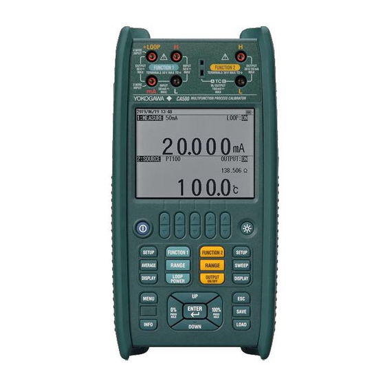
Page 18: Component Names And Functions
Cancels settings or Displays an instrument setup returns to the previous menu screen File key COM key (CA550 only) Saves and loads Performs HART/BRAIN measured values (to be supported in the near future) Cursor keys and ENTER key INFO key... - Page 19 1 Component Names and Functions Function Set Keys Function 1 setup keys Selects the measurement Sets the 0 and 100% value function (voltage, current, and the pulse contact input resistance, RTD, pulse, off) on/off Selects the measurement Turns on/off the moving range average function and the max/min display...
-
Page 20: Side Panel And Rear Panel
USB port (type B) Can be used to control the instrument remotely from a PC and supply power to the instrument. On the CA550, data control can be performed according to the USB mass storage class. Rear Panel Stand... -
Page 21: Display
1 Component Names and Functions 1.3 Display Displayed when pulse contact input is on and function is set to PULSE Average display Displayed when auto power-off is on 0, 100% value Displayed when display light is on Power supply state Displayed when USB: Measurement... - Page 22 1 Component Names and Functions Main Displays and Sub Displays Each time you press the DISPLAY key of function 1 or 2, the main display switches between showing the physical value and percentage. When the main display is showing the physical value, sub display 1 shows the percentage, and vice versa. Sub display 2 shows the thermoelectromotive force of a thermocouple, the resistance of an RTD.
- Page 23 1 Component Names and Functions Select Menu When setting a function, available options are displayed at the bottom of the screen. Press the arrow key corresponding to the option you want to select. For two-row selection menus, the up arrow key corresponds to the top area and the down arrow key to the bottom area.
-
Page 24: Preparation Before Use
If you notice smoke or unusual odors coming from the instrument, immediately turn off the power, remove the batteries if possible, and contact your nearest YOKOGAWA dealer. Also, turn off the power to source/measurement targets that are connected to the input terminals. - Page 25 2 Preparation before Use Remove the Batteries during Extended Non-Use Remove the batteries from the main unit. When Carrying the Instrument First, turn off the device under measurement. Next, turn off the instrument. When USB power supply is in use, remove the USB cable. Then, remove all the cables.
-
Page 26: Installing The Instrument
2 Preparation before Use 2.2 Installing the Instrument WARNING • Install the instrument so that you can immediately turn off the power if an abnormal or dangerous condition occurs. • Do not use the instrument to measure locations that fall under Measurement Categories II, III, and IV. - Page 27 2 Preparation before Use Installation Conditions Install the instrument in a place that meets the following conditions. • Operating Altitude and Ambient Temperature and Humidity • Use the instrument in the following environment. • Ambient temperature -10°C to 50°C • Ambient humidity 80% RH or less for -10°C to 40°C, 50% RH or less for over 40°C No condensation...
- Page 28 Entrance cables, cable source circuits systems, etc. The estimated transient overvoltage that may appear at the CA500 and CA550 signal input terminals is 500 V. Fastening the Shoulder Strap Fasten the shoulder strap to the strap fastening area at the top section on each side of the instrument.
-
Page 29: Connecting Cables
2 Preparation before Use 2.3 Connecting Cables WARNING Maximum Voltage Application Between Terminals And Earth The maximum voltage application between measurement terminals and earth is 50 VDC, and that of the source terminals is 30 VDC. To prevent electric shock, do not exceed these voltages. Source Terminals To prevent electric shock, observe the following: •... - Page 30 2 Preparation before Use Bornes de Source Pour éviter le choc électrique, observer les points suivants: • Veiller à ne pas appliquer les tensions dépassant les tensions nominales de chaque borne. • Veiller à utiliser les câbles de raccordement de la source fournis. Bornes de Mesure •...
- Page 31 2 Preparation before Use DC Voltage Source DC current source 30V/ − − DC Voltage Measurement DC Current Measurement − − 20 mA simulate − Loop Power − IM CA500-02EN...
- Page 32 2 Preparation before Use Thermocouple measurement Thermocouple Source When using the TC-A mini plug terminal When using the TC-A mini plug terminal − − − − − When using the banana plug* When using the banana plug* Resistance/RTD Source Resistance/RTD Measurement (4W) Ω...
- Page 33 2 Preparation before Use Using Thermocouple Mini Plugs The TC-A terminal is a dedicated thermocouple mini plug terminal. Using the thermocouple mini plug results in more stable reference junction compensation then using a banana terminal. Use the same type of thermocouple mini plug as the plug on the item to be calibrated (thermocouple or range of the device to be calibrated).
-
Page 34: Loading And Removing Batteries
2 Preparation before Use 2.4 Loading and Removing Batteries WARNING • Never replace the batteries with the main unit turned on. • Insert batteries with the correct polarity as shown inside the battery holder. Otherwise, the batteries may leak, heat up, or burst. •... - Page 35 2 Preparation before Use Remove the battery cover. Insert new batteries into the battery holder. Insert the batteries in the correct orientation according to the polarity markings in the battery holder. Attach the battery cover. Insert the battery cover tab into the battery holder hole, and close the battery cover.
-
Page 36: Supplying Power Through The Usb Terminal
2 Preparation before Use 2.5 Supplying Power through the USB Terminal WARNING • Use a USB power supply that can supply stable power and that complies with the specifications of this instrument • For details on handling the USB power supply, follow the instruction manual of the power supply. -
Page 37: Turning The Power On And Off
• Batteries of different types or different brands are being used together. • Check whether the power supply that you are using can supply a current of 500 mA or more. If the instrument still does not work properly, contact your nearest YOKOGAWA dealer for repairs. IM CA500-02EN... -
Page 38: Setting The Date And Time
2 Preparation before Use Turning the Power Off CAUTION • Do not turn off the instrument when the instrument’s output is turned on. Doing so can damage the instrument. It can also cause damage to the devices connected to the instrument. Turn off the output first and then the instrument. - Page 39 2 Preparation before Use Use the cursor keys to select Date, and then press ENTER. The date is displayed at the bottom of the screen. Using the arrow keys corresponding to the digits you want to set, set the year, month, and day. Press ENTER.
-
Page 40: Common Operations
Common Operations 3.1 Opening and Closing Setup Screens To open a setup screen, press the appropriate key on a screen showing the measured value or source value. After entering the settings, to confirm the settings and close the screen, select Exit Setup from the selection menu. -
Page 41: Selection Menu Operation
3 Common Operations 3.3 Selection Menu Operation When a selection menu appears at the bottom of the screen, use the arrow keys to make selections. When the setup menu has one row Select items When the setup menu has two rows Select items in the top row Select items in the bottom row 3.4 Specifying Values... -
Page 42: Setting Alphanumeric Characters
3 Common Operations 3.5 Setting Alphanumeric Characters Select an item you want to set alphanumeric characters for and press ENTER to display a window for entering alphanumeric characters. Character input position Use the cursor keys to select the character and the ENTER key to input the character. Switches the selected character to “number + uppercase character”... -
Page 43: Troubleshooting, Maintenance, And Inspection
Faults and Corrective Actions If servicing is necessary, or if the instrument does not operate properly even after you have attempted to deal with the problem according to the instructions in this section, contact your nearest YOKOGAWA dealer. Problems and Solutions Reference Page The instrument Check the battery level. -
Page 44: Error Codes, Error Messages, And Corrective Actions
4 Troubleshooting, Maintenance, and Inspection 4.2 Error Codes, Error Messages, and Corrective Actions Information and Warning Messages Message Cause Corrective Action Memory error Insufficient free internal Delete unneeded data. memory space Low power error Low battery level Replace the batteries, or switch to Low USB power a USB power supply that meets the power supply specifications. -
Page 45: Displaying Instrument Information
Factory Calibration Date (performed at YOKOGAWA) 4.4 Recommended Replacement Parts, Consumable Parts, and Calibration Recommended Replacement Parts and Consumable Parts YOKOGAWA guarantees the instrument for the period and under the conditions of the product warranty. Calibration To ensure accuracy, we recommend periodic calibration. -
Page 46: Specifications
DC Voltage Source Accuracy (1 year) ±(% of setting + offset) Range Resolution Source Range Notes CA500 CA550 100 mV 1 μV ±110.000 mV 0.015% + 10 μV 0.015% + 5 μV Maximum output current: 10 mA 1-5V 0.1 mV 0.0000 to... - Page 47 Range Resolution Source Range Accuracy (1 year) Notes ±(% of setting + offset) CA500 CA550 400 Ω 10 mΩ 0.00 to 440.00 Ω 0.020% + 0.1 Ω 0.015% + 0.05 Ω Allowable measurement current: 0.1 to 3 mA 4000 Ω 100 mΩ...
-
Page 48: Dc Voltage, Dc Current, Resistance And Pulse Measurement
DC Voltage Measurement Accuracy (1 year) Measurement ±(% of reading + offset) Range Resolution Notes Range CA500 CA550 100 mV 1 μV ±110.000 mV 0.015% + 10 μV 0.015% + 5 μV Input resistance: 1 GΩ or more 0.1 mV ±6.0000 V 0.015% + 0.5 mV... - Page 49 Accuracy (1 year) Notes Range ±(% of setting + offset) CA500 CA550 400 Ω 10 mΩ 0.00 to 440.00 Ω 0.020% + 0.1 Ω 0.015% +0.05 Ω Voltage applied current measurement method 4000 Ω 100 MΩ 0.0 to 4400.0 Ω 0.020% + 0.5 Ω 0.015% +0.2 Ω...
-
Page 50: Temperature Measurement (Tc) And Thermocouple Calibration Voltage Source
Thermocouple Calibration Voltage Source When the TC-A terminal (thermocouple plug terminal) and reference junction compensation using the internal temperature sensor are in use Source Accuracy (common to CA500 and CA550 ) Accuracy (1 year, t: source temperature) Thermocouple Temperature Range... - Page 51 Display resolution of source/measured values: 0.1°C 1 Complies also with JIS C 1602 2 The setting can be changed to comply with IPTS-68 (JIS C 1602 1981). Measurement Accuracy (common to CA500 and CA550 ) Accuracy (1 year, t: measurement temperature) Thermocouple...
- Page 52 5. Specifications Accuracy (1 year, t: measurement temperature) Temperature Range Measurement Thermocouple Specification ± Accuracy [°C] 1, 2 -20.0°C ≤ t < 0.0°C IEC60584-1 0.0°C ≤ t < +100.0°C +100.0°C ≤ t ≤ +1767.0°C 1, 2 -20.0°C ≤ t < 0.0°C IEC60584-1 0.0°C ≤...
- Page 53 5. Specifications When terminal B (banana terminal) and reference junction compensation using the internal temperature sensor are in use Source Accuracy (common to CA500 and CA550 ) Accuracy (1 year, t: source temperature) Thermocouple Specification Temperature Range Source Accuracy ±...
- Page 54 Accuracy when using the included binding post (99045). 1 Complies also with JIS C 1602 2 The setting can be changed to comply with IPTS-68 (JIS C 1602 1981). Measurement Accuracy (common to CA500 and CA550 ) Accuracy (1 year, t: measurement temperature) Thermocouple...
- Page 55 5. Specifications Accuracy (1 year, t: measurement temperature) Thermocouple Specification Temperature Range Measurement ± Accuracy [°C] 1, 2 -20.0°C ≤ t < 0.0°C 1.6+|t-100| x 0.50% IEC60584-1 0.0°C ≤ t < +100.0°C 1.6+|t-100| x 0.50% +100.0°C ≤ t ≤ +1768.0°C 1, 2 +600.0°C ≤...
- Page 56 5. Specifications When terminal B (banana terminal) and reference junction compensation using the external RJ sensor (sold separately) are in use Source Accuracy (common to CA500 and CA550 ) Accuracy (1 year, t: source temperature) Thermocouple Specification Temperature Range Source Accuracy ±...
- Page 57 Accuracy when using the included binding post (99045). 1 Complies also with JIS C 1602 2 The setting can be changed to comply with IPTS-68 (JIS C 1602 1981). Measurement Accuracy (common to CA500 and CA550 ) Accuracy (1 year, t: measurement temperature) Thermocouple...
- Page 58 5. Specifications Accuracy (1 year, t: measurement temperature) Thermocouple Specification Temperature Range Measurement ± Accuracy [°C] 1, 2 -20.0°C ≤ t < 0.0°C 1.4+|t-100| x 0.50% IEC60584-1 0.0°C ≤ t < +100.0°C 1.4+|t-100| x 0.50% +100.0°C ≤ t ≤ +1768.0°C 1, 2 +600.0°C ≤...
- Page 59 5. Specifications When terminal B (banana terminal) is in use and reference junction compensation is off Source Accuracy (common to CA500 and CA550 ) Accuracy (1 year, t: source temperature) Thermocouple Specification Temperature Range Source Accuracy ± [°C] 1, 2 -200.0°C ≤...
- Page 60 Accuracy when using the included binding post (99045). 1 Complies also with JIS C 1602 2 The setting can be changed to comply with IPTS-68 (JIS C 1602 1981). Measurement Accuracy (common to CA500 and CA550 ) Accuracy (1 year, t: measurement temperature) Thermocouple...
- Page 61 5. Specifications Accuracy (1 year, t: measurement temperature) Thermocouple Specification Temperature Range Measurement ± Accuracy [°C] 1, 2 -20.0°C ≤ t < 0.0°C IEC60584-1 0.0°C ≤ t < +100.0°C +100.0°C ≤ t ≤ +1768.0°C 1, 2 +600.0°C ≤ t < +800.0°C IEC60584-1 +800.0°C ≤...
- Page 62 5. Specifications Common Specifications Source/measurement temperature to voltage conversion function Terminal type selection function: TC-A/TC-B terminal Temperature monitor function: Temperature measurement of the reference junction compensation sensor for the selected terminal type Reference junction compensation function: Can be disabled when using the TC-B terminal An external reference junction compensation sensor can be selected when using the TC-B terminal.
-
Page 63: Temperature Measurement (Rtd) And Resistance Source For Rtd Calibration
5. Specifications 5.4 Temperature Measurement (RTD) and Resistance Source for RTD Calibration CA500 Coef Source/measurement accuracy (1 year, Allowable Standard, t: source/measurement temperature) Excitation Citation Current Temperature Range ± CA500 [°C] 3851 -200.0°C ≤ t < +100.0°C 0.3 0.1 to 3 mA IEC60751 +100.0°C ≤... - Page 64 Assume the accuracies through two-wire system measurement to be the same as those through three-wire system measurement. However, cable resistance are not taken into consideration. Display resolution of source/measured values: 0.1°C 1 Complies also with JIS C 1604 CA550 Coef Source/measurement accuracy (1 year, Allowable Standard, t: source/measurement temperature)
- Page 65 Allowable Standard, t: source/measurement temperature) Excitation Citation Current Temperature Range ± CA550 [°C] -200.0°C ≤ t < +100.0°C 0.2 0.1 to 3 mA GOST R 8.625-2006 PT50G +100.0°C ≤ t ≤ +800.0°C 0.2+(t-100)x 0.033% -200.0°C ≤ t < +100.0°C 0.1 0.1 to 3 mA GOST R...
-
Page 66: Common Specifications
5. Specifications 5.5 Common Specifications Common Source Section Specifications Source section voltage limiter Approx. -5 V to 36 V Source section current limiter Approx. 30 mA Sweep function Step/Linear/Programr Interval time 5 to 600 s C≤10 μF, L≤10 mH Maximum load Output resistance 20 mΩ... -
Page 67: General Specifications
Between FUNCTION1 terminal and FUNCTION2 terminal: 500 VAC for 10 seconds Number of Saved Data CA500: Up to 100 results Values CA550: Up to 250 CSV files Interface CA500: USB B Communication Device Class CA550: USB B Communication Device Class... - Page 68 5. Specifications Item Specifications EMC Emissions Compliant standards: EN 61326-1 Class A, EN 55011 Class A Group1 EMC Regulatory Arrangement in Australia and New Zealand EN 55011 Class A, Group 1 Korea Electromagnetic Conformity Standard ( 한국 전자파적합성기준 ) This product is classified as Class A (for use in industrial environments).
- Page 69 5. Specifications External Dimensions Unit: mm Unless otherwise specified, tolerances are ±3% (however, tolerances are ±0.3 mm when below 10 mm). IM CA500-02EN...
Need help?
Do you have a question about the CA550 and is the answer not in the manual?
Questions and answers