Page 1
DLM 2000 DLM 2000 Series Series Series 
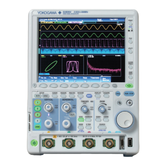
Mixed Signal Oscilloscope Lineup includes 200 MHz, 350 MHz, 500 MHz bandwidth models Lightweight and compact Large 8.4-inch LCD display Long memory: Up to 250 M points (with /M3 option) High speed sampling: Up to 2.5 GS/s (1.25 GS/s with 4 ch) -Year Warranty -Year Warranty Bulletin 7101-00E...
Page 2
sab i li ty lexibilit y Compact & intuitive operation Switch between analog and logic channels Flexible MSO input Four channels is not sufficient to view the functioning of digital control circuits. The DLM2000 series converts 4 ch of analog input to 8-bit logic, and functions as a 3 ch analog + 8-bit logic MSO (mixed signal oscilloscope).
Page 3
a paci ty Best-in-class long memory Large capacity memory up to 250 Mpoints Long memory is necessary to keep high speed sample rate in long term measurement. <Basic Formula> Measuring time = Memory length/Sample rate If 250 Mpoints (Memory expansion option /M3) is installed, Max. 0.2 sec waveform can be captured even at 1.25 GS/s sample rate when taking 2 ch measurements in Single mode.
riginali ty Original History function Automatically save previously captured waveforms You can replay waveforms later on, so you'll never miss an abnormal waveform HISTORY With the DLM2000 series, up to 50000 previously captured waveforms can be saved in the acquisition memory. With the History function, you can display just one or all of the previously captured waveforms (history waveforms) on screen.
Page 5
un ctiona li ty Large selection of triggers and filters Real time filter with optimum noise reduction supports a wide range of frequencies (from 8 kHz to 200 MHz) The DLM2000 series has two types of filters, one processed at the input circuit and one based on MATH functions. These filters are effective for rejecting unwanted signals, allowing observation of only the desired bandwidths.
Page 6
t il ity Range of functions that help operation efficiency Displays trends of peak-to-peak or pulse width per cycle —Measure function and statistics— —Trend and histogram displays— Twenty-nine waveform Waveform parameters such parameters are included as period, pulse width, and such as: maximum, amplitude can be measured minimum, peak-to-peak,...
Page 7
p ecia lty Analysis option for application Serial analysis function options (/F1 to /F11) —UART (RS232)/I C/SPI/CAN/CAN FD/LIN/FlexRay/SENT/PSI5/CXPI— Triggers for embedded systems and in-vehicle bus signals are supported along Inputs supported for serial bus analysis with decode display analysis (serial bus analysis option only on 4 ch models. C SPI UART LIN CAN CAN FD FlexRay SENT PSI5 CXPI Trigger functions of some of the serial buses are not supported).
Transferring les 8 GP-IB connection terminal (optional) is easy even when a USB thumb drive can’t be used. mouse keyboad 9 Probe power terminal (optional) Software Control http://tmi.yokogawa.com/ea/products/oscilloscopes/oscilloscopes-application-software/ Free Software Optional Software Trial version available Off-line waveform Xviewer XviewerLITE –Basic check–...
Page 9
Logic Signal Input (4 ch model only) Trend/Histogram display Up to 2 trend or histogram display of specified wave parameters Number of inputs 8 bit (excl. 4 ch input and logic input) of wave parameters Maximum toggle frequency Model 701988: 100 MHz, Model 701989: 250 MHz Computations (MATH) +, −, ×, Filter (Delay, Moving Avg, IIR Lowpass, IIR Highpass), Integ, Count (Edge, Rotary), user defined math (optional)
Page 10
Mass Storage Class Ver. 1.1 compliant mass storage devices* Please contact List display items Analysis no., time from trigger position (Time (ms)), Frame type, ID, your local YOKOGAWA sales office for model names of verified devices DLC, Data, CRC, presence/absence of Ack, information Auxiliary analysis functions Field jump functions...
Page 11
*1: Logic probes sold separately. Please order the model 701988/701989 accessory logic probes separately. *2: One of these must be selected. • Yokogawa’s electrical products are developed and produced in facilities that have *3: Specify this option when using current probes or other differential probes that don't support probe interface.
Need help?
Do you have a question about the DLM 2000 Series and is the answer not in the manual?
Questions and answers